Mounting HONDA CR-V 1999 RD1-RD3 / 1.G Owner's Manual
[x] Cancel search | Manufacturer: HONDA, Model Year: 1999, Model line: CR-V, Model: HONDA CR-V 1999 RD1-RD3 / 1.GPages: 1395, PDF Size: 35.62 MB
Page 438 of 1395
Release Bearing
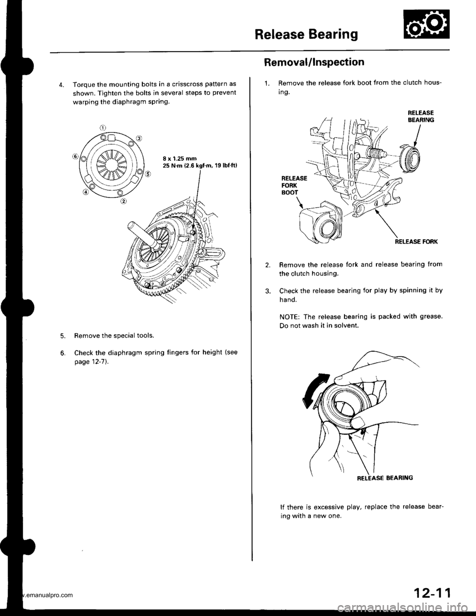
4. Torque the mounting bolts in a crisscross pattern as
shown. Tighten the bolts in several steps to prevent
warping the diaphragm spring.
8 x 1.25 mm25 N.m (2.6 kgf.m, 19lbfft)
Remove the special tools.
Check the diaphragm spring fingers for height (see
page 12-7]'.
5.
6.
Removal/lnspection
1. Remove the release fork boot from the clutch hous-
Ing.
RELEASEBEABING
RELEASEFORKBOOT
\
RELEASE FORK
Remove the release fork and release bearing from
the clutch housing.
Check the release bearing for play by spinning it by
ha nd.
NOTE: The release bearing is packed with grease.
Do not wash it in solvent.
lf there is excessive play, replace the release bear-
ing with a new one.
12-11
www.emanualpro.com
Page 450 of 1395
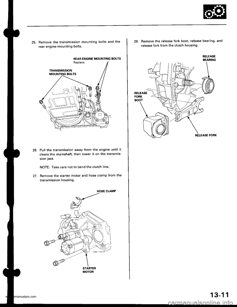
25. Remove the transmission mounting bolts and the
rear engine mounting bolts.
REAR ENGINE MOUNTING BOLTSReplace.
TRANSMISSION
Pull the transmission away from the engine until it
clears the mainshaft, then lower it on the transmis-
sion jack.
NOTE: Take care not to bend the clutch line.
Remove the starter motor and hose clamp from the
transmission housing.
STARTERMOTOR
28. Remove the release tork boot. release bearing, and
release fork from the clutch housing
RELEASEBEANING
13-1 1
www.emanualpro.com
Page 454 of 1395
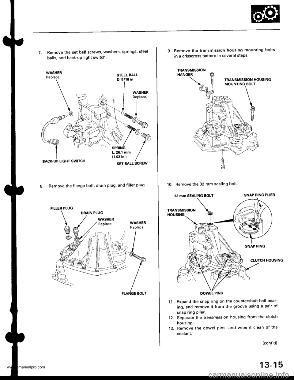
7. Remove the set ball screws, washers, springs, steel
balls. and back-uP light switch.
STEEL BALLD. 5/16 in
8. Remove the flange bolt. drain plug, and filler plug
DRAIN PLUG
WASHERReplace.
LIGHT SWITCH
FILLER PLUG
WASHERReplace.
FLANGE BOLT
9. Remove the transmission housing mounting bolts
in a crisscross pauern in several steps.
10. Remove the 32 mm sealing bolt
Expand the snap ring on the countershaft ball bear-
ing, and remove it from the groove using a pair of
snap ring plier.
Separate the transmission housing from the clutch
housing.
Remove the dowel pins, and wipe it clean of the
sealant.
'I t.
(cont'd)
13-15
www.emanualpro.com
Page 511 of 1395
Transmission Assembly
1.
Installation
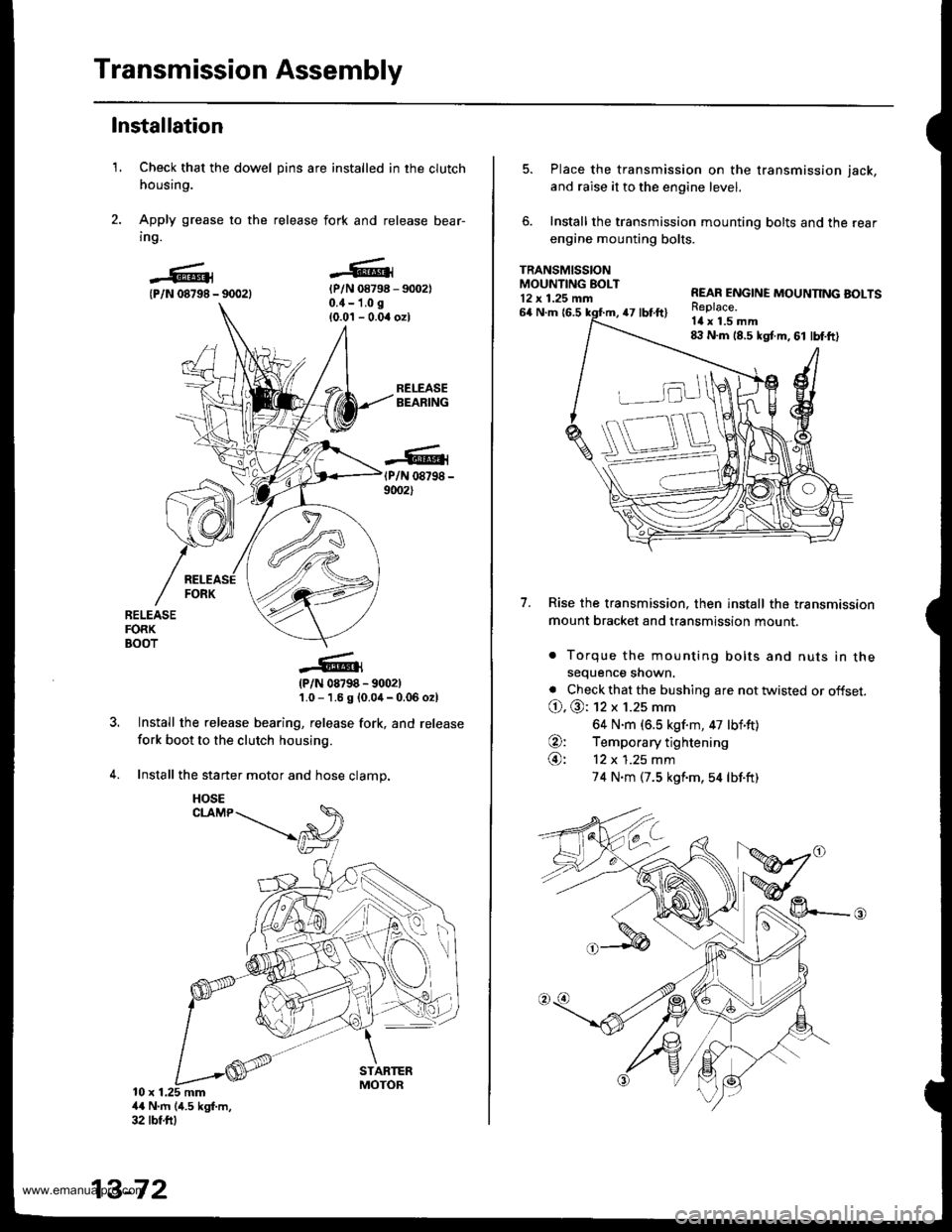
Check that the dowel pins are installed in the clutch
housing.
Apply grease to the release fork and release bear-
ing.
{P/N 08798 - 90021{P/N 08798 - 9002)0.{ - 1.0 g
{0.0'l - 0.04 ozl
RELEASEBEARING
(P/N 08798 -
9002)
RELEASEFORKBOOT
?
(P/N 08798 - 9002)'1.0 - 1.6 g {0.0,1- 0.06 o2l
Install the release bearing, release fork, and release
fork boot to the clutch housing.
Install the starter motor and hose clamp.
10 x 1.25 mm4{ N'm (4.5 kgf.m,32 tbf.ftl
13-72
HOSE
5. Place the transmission on the transmission jack,
and raise it to the engine level.
6. Install the transmission mounting bolts and the rear
engine mounting bolts.
TRANSMISSIONMOUNTING EOLT12 x 1.25 mn
7.
64 N.m {6.547 tbt.ft)
REAR ENGINE MOUNNNG BOLTSReplace.Itl x 1.5 mm8:l N.m 18.5 kgt m, 61 lbf.ft)
Rise the transmission, then install the transmission
mount bracket and transmission mount.
. Torque the mounting bolts and nuts in thesequence shown.
. Check that the bushing are not twisted or offset.
O. @: 12 x 1.25 mm
64 N.m (6.5 kgf.m, 47 lbf'ft)
O: Temporary tightening
@: 12 x 1.25 mm
74 N.m (7.5 kgf'm,54 lbf.ft)
www.emanualpro.com
Page 514 of 1395
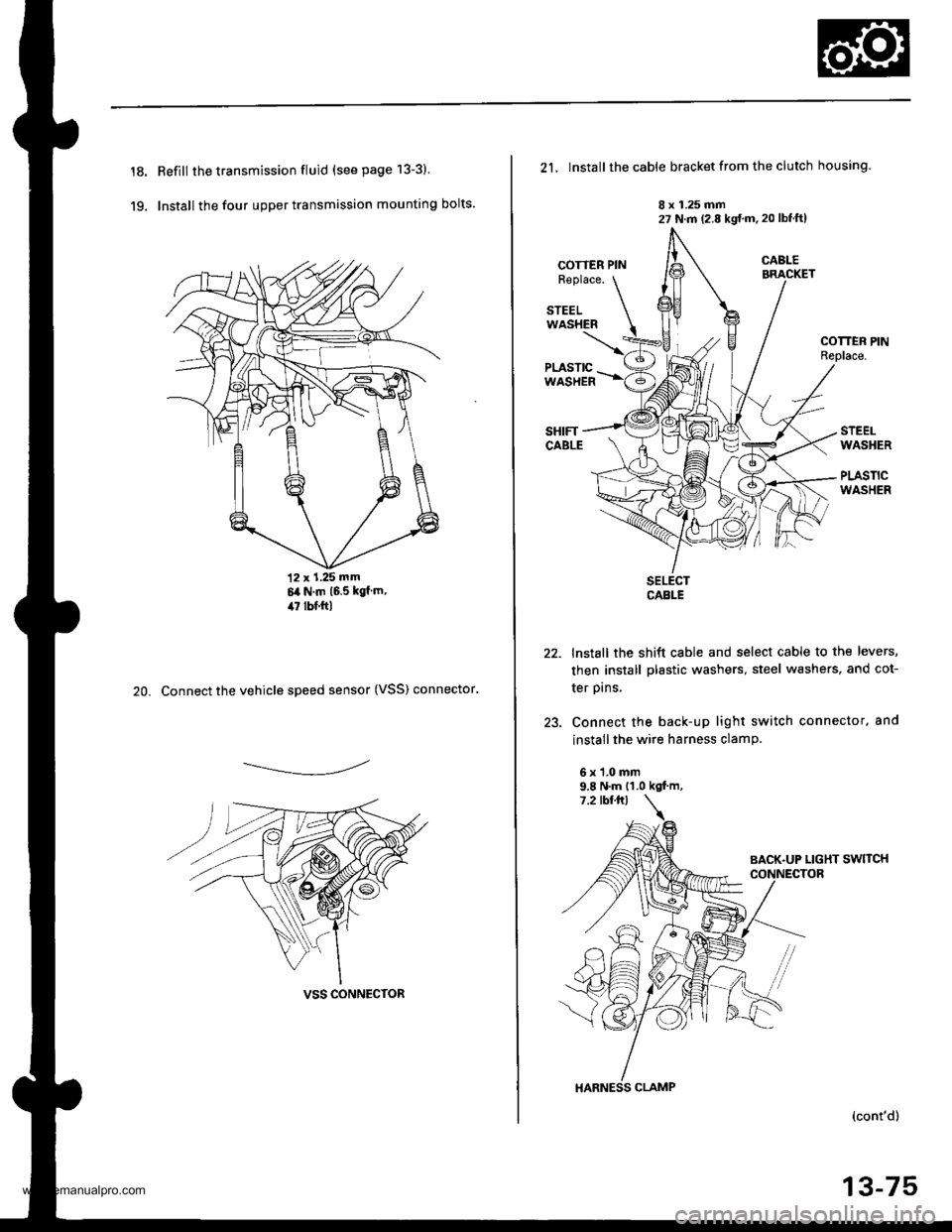
18.
19.
Refill the transmission fluid (see page 13-3)
Install the four upper transmission mounting bolts.
12 x 1.25 mm6it N.m 16.5 kgf m,il7 lbf.ftl
20. Connect the vehicle speed sensor (VSS) connector.
------------,-
VSS CONNECTOR
21, Install the cable bracket from the clutch housing.
8 x 1.25 mm27 N.m (2.8 kgt'm. 20 lbtftl
COTTER PINR€place.
STEELWASHER
COTTEN PINReplace.
STEELWASHER
PLASTICWASHER
22.
)a
SELECTCABLE
lnstall the shift cable and select cable to the levers,
then install plastic washers, steel washers, and cot-
ter prns,
Connect the back-up light switch connector. and
install the wire harness clamP.
6x1.0mm9.8 N.m {1.0 kgf.m,
HARNESS CLAMP
(cont'd)
13-75
www.emanualpro.com
Page 651 of 1395
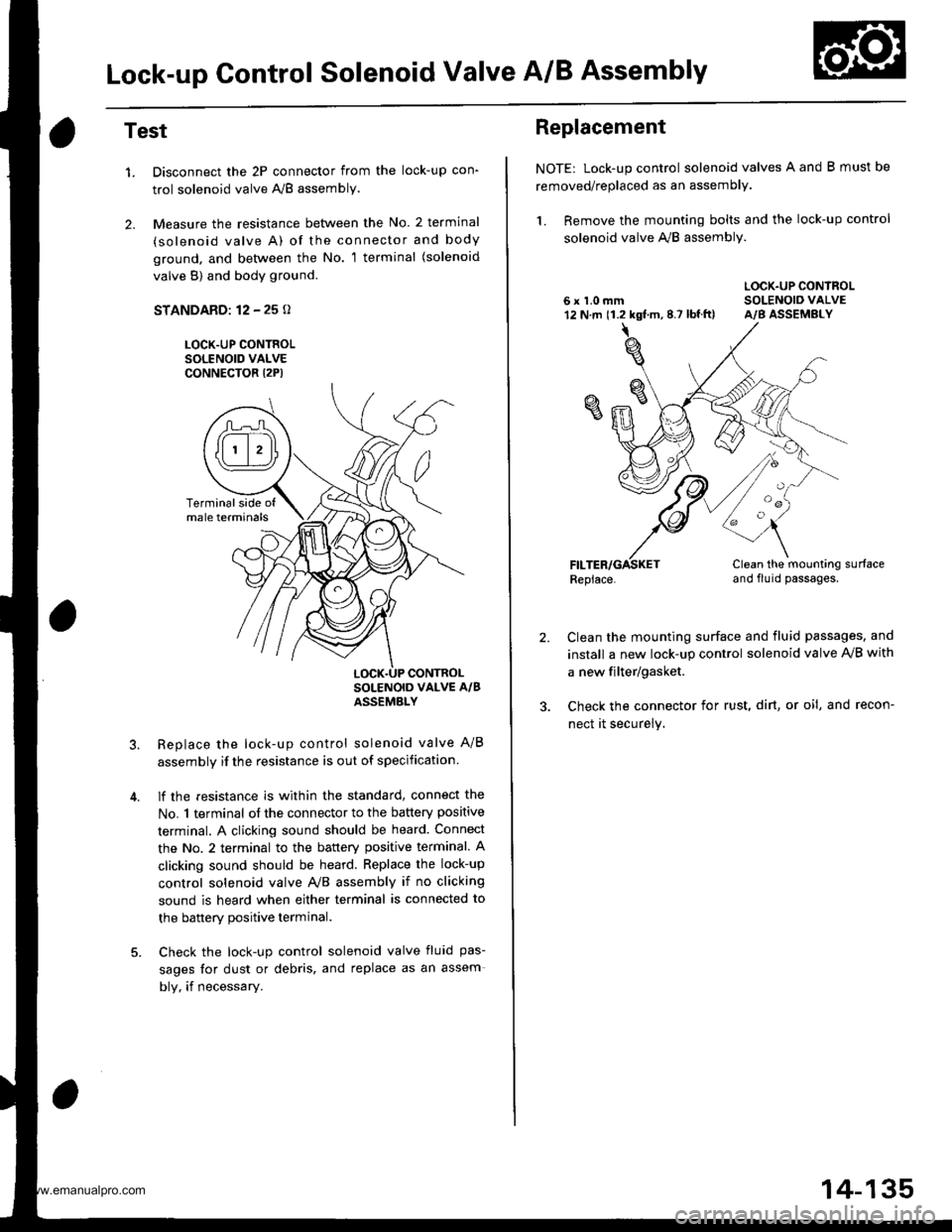
Lock-up Control Solenoid Valve A/B Assembly
Test
1.
2.
Disconnect the 2P connector from the lock-up con'
trol solenoid valve A'lB assembly.
Measure the resistance between the No. 2 terminal
(solenoid valve A) of the connector and body
ground. and bet\iveen the No. 1 terminal (solenoid
valve B) and body ground.
STANDARD: 12 - 25 o
LOCK-UP CONTROLSOLENOID VALVECONNECTOR I2P)
Replace the lock-up control solenoid valve A/B
assembly if the resistance is out of specification
lf the resistance is within the standard, connect the
No. 1 terminal of the connector to the battery positive
terminal. A clicking sound should be heard Connect
the No. 2 terminal to the battery positive terminal. A
clicking sound should be heard. Replace the lock-up
control solenoid valve Ay'B assembly if no clicking
sound is heard when either terminal is connected to
the banerv Dositive terminal.
Check the lock-up control solenoid valve fluid pas-
sages for dust or debris, and replace as an assem
bly, if necessary.
Terminalside ofmale terminals
LOCK.UP CONTROL
Replacement
NOTE: Lock-up control solenoid valves A and B must be
removed/replaced as an assembly.
1. Remove the mounting bolts and the lock-up control
solenoid valve A,,/B assembly.
LOCK.UP CONTROL6 x 1.0 mm SOLENOIO VALVE12 N.m 11.2 kgf.m,8.7 lbf.ft) A/B ASSEMBLY
Replace.Clean the mounting surfaceand flu id passages.
2.Clean the mounting surface and fluid passages, and
install a new lock-up control solenoid valve IVB with
a new filter/gasket.
Check the connector for rust, dirt, or oi!, and recon-
nect it securely.
oa
14-135
www.emanualpro.com
Page 652 of 1395
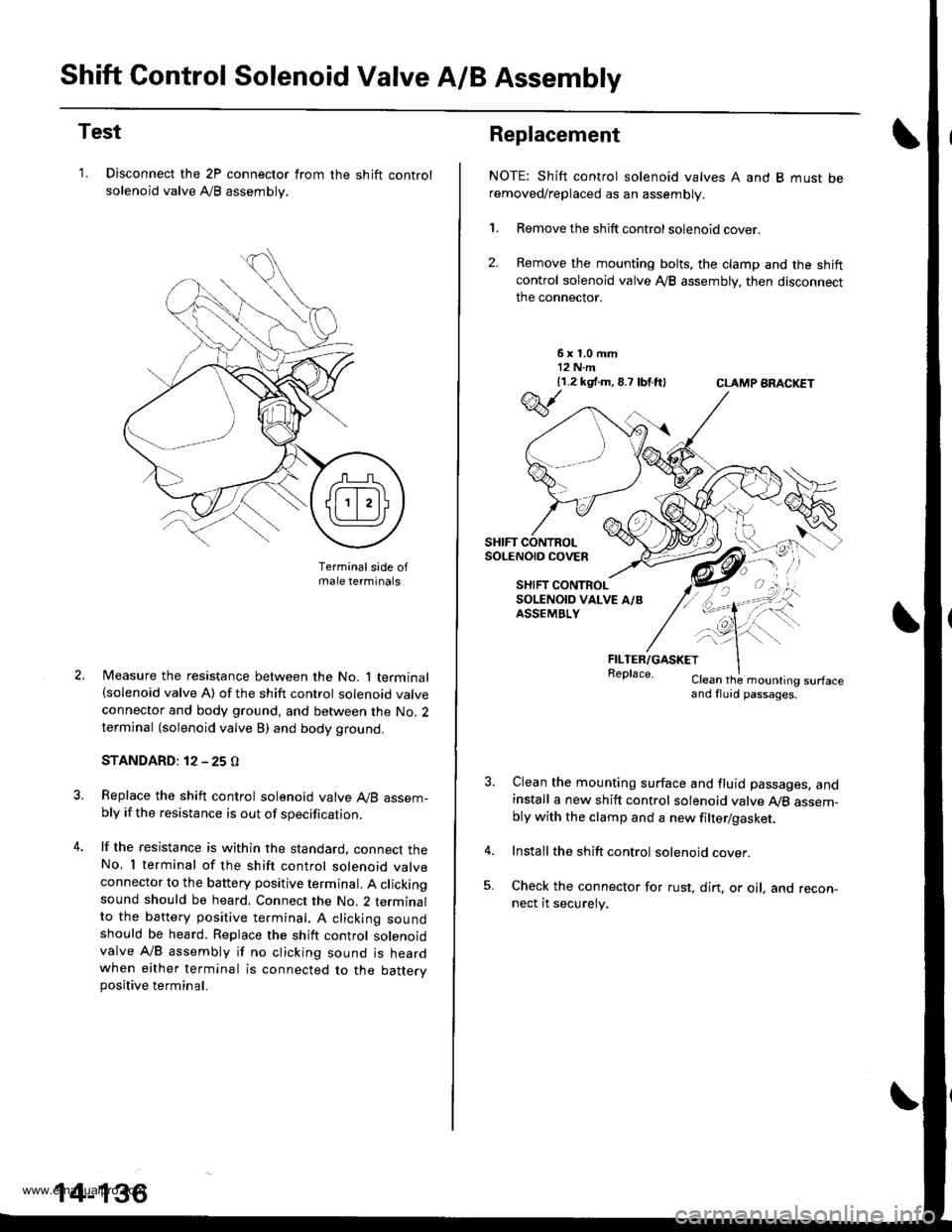
Shift Control Solenoid Valve A/B Assembly
Test
'1. Disconnect the 2P connector from
solenoid valve Ay'B assembly.
the shift control
Terminalsade ofmale terminals
Measure the resistance between the No. 1 terminal(solenoid valve A) of the shift control solenoid valve
connector and body ground, and between the No. 2terminal (solenoid valve B) and body ground.
STANDARD: 12 - 25 O
Replace the shift control solenoid valve A,/B assem-bly if the resistance is out of specification.
lf the resistance is within the standard. connect theNo, I terminal of the shift control solenoid valveconnector to the battery positive terminal. A clickingsound should be heard. Connect the No. 2 terminalto the battery positive te.minal. A clicking soundshould be heard. Replace the shift control solenoidvalve A/B assembly if no clicking sound is heardwhen either terminal is connected to the battervpositive terminal.
14-136
Replacement
NOTE: Shift control solenoid valves A and B must beremoved/replaced as an assembly.
1. Remove the shift control solenoid cover.
2. Remove the mounting bolts, the clamp and the shiftcontrol solenoid valve Ay'B assembly, then disconnect
the connector.
6x1.0mm12 N.m{1.2 k9 .m,8.7 lbtft}CLAMP ARACKET
FILTER/GASKETReplace.Clean the mounling surfaceand fluid passages.
Clean the mounting surface and fluid passages. andinstall a new shift control solenoid valve Ay'B assem-bly with the clamp and a new filter/gasket.
Install the shift control solenoid cover.
Check the connector for rust, dirt. or oil, and recon-nect it securely.
w
SHIFT CONTROLSoLENO|O COVEn
SHIFT CONTROLSOLENOID VALVE A/BASSEMBLY
\--
qK
-!t'">,,
www.emanualpro.com
Page 653 of 1395
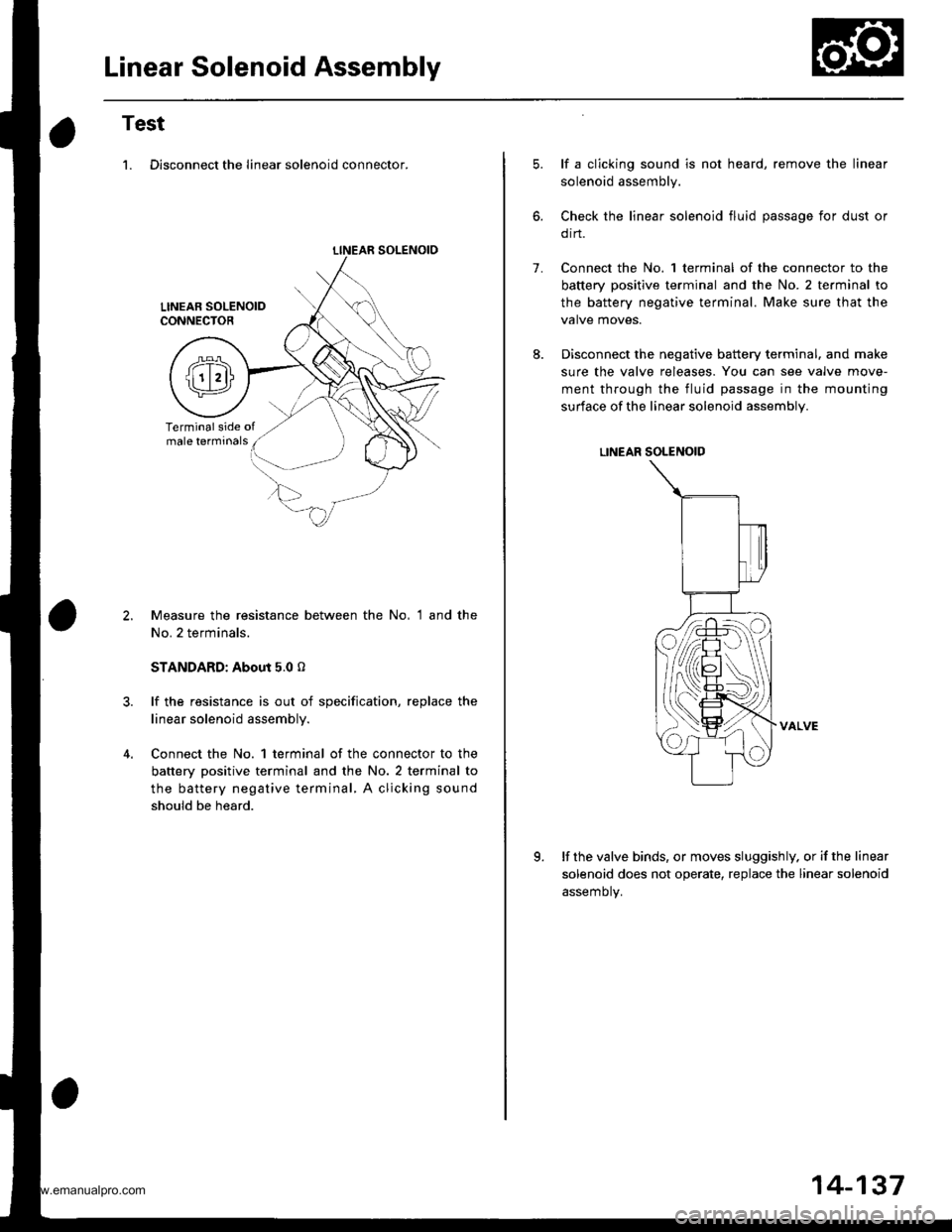
Linear Solenoid Assembly
Test
1. Disconnect the linear solenoid connector.
LINEAR SOLENOIO
Measure the resistance between the No, 1 and the
No. 2 terminals.
STANDARD: About 5.0 o
lf the resistance is out of specification, replace the
linear solenoid assembly.
Connect the No. 1 terminal of the connector to the
battery positive terminal and the No. 2 terminal to
the battery negative terminal, A clicking sound
should be heard.
1.
lf a clicking sound is not heard, remove the linear
solenoid assembly.
Check the linear solenoid fluid passage for dust or
orn.
Connect the No. 1 terminal of the connector to the
battery positive terminal and the No. 2 te.minal to
the battery negative terminal. Make sure that the
valve moves.
Disconnect the negative battery terminal. and make
sure the valve releases. You can see valve move-
ment through the fluid passage in the mounting
surface of the linear solenoid assembly.
LINEAR SOLENOID
VALVE
lf the valve binds, or moves sluggishly. or if the linear
solenoid does not operate, replace the linear solenoid
assemotv.
K
14-137
www.emanualpro.com
Page 654 of 1395
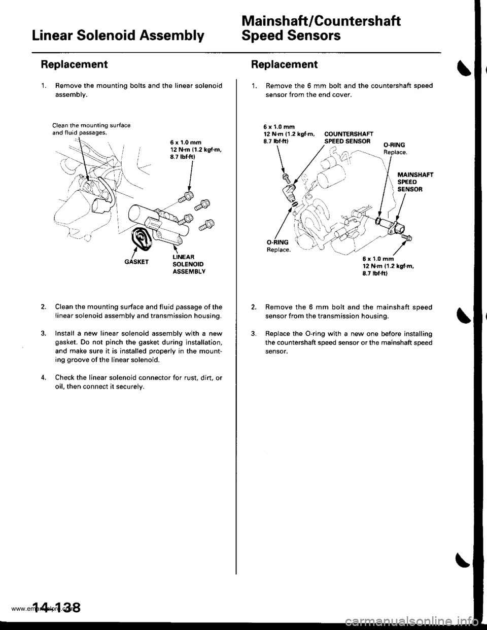
Mai nshaft /Cou ntershaft
Linear Solenoid AssemblySpeed Sensors
Replacement
'1. Remove the mounting bolts and the linear solenoid
assemblY.
Clean the mounting surfaceand fluid passages.
6x1.0mm12 N.m (1.2 kg{.m.8.7 tbtftl
@
@
GASKET
Clean the mounting surface and fluid passage of the
linear solenoid assembly and transmission housing.
Install a new linear solenoid assemblv with a new
gasket. Do not pinch the gasket during installation,
and make sure it is installed properly in the mount-
ing groove of the linear solenoid.
Check the linear solenoid connector for rust. dirt, or
oil, then connect it securelv.
14-138
Replacement
1. Remove the 6 mm bolt and the countershaft sDeed
sensor from the end cover.
\
5x1.0mm12 N.m 11.2 kgf.m, COUNTERSHAFT8.7 rbf.frl SPEED SENSOR
O.RINGReplace.
12 N'm 11.2 kgl.m,8.7 tbf.ftl
Remove the 6 mm bolt and the mainshaft speed
sensor from the transmission housing.
Replace the O-ring with a new one before installing
the countershaft speed sensor or the mainshaft speed
sensor,
6x1.0mm
www.emanualpro.com
Page 685 of 1395

Transmission
Removal
@
2.
'1.
Make sure lifts. iacks, and safety stands aro placed
properly, and hoist brackets are attached to the col-
rest position on the engine lsee section 11.
Apply th€ parking brake and block the r€ar wheels,
so vehicls will noi roll off the stands and fall on you
while working under it.
NOTE: Use fender covers to avoid damaging painted
surfaces.
Disconnect the negative terminal, then disconnect
the positive terminal from the battery.
Remove the intake air duct and the air cleaner hous-
ing assembly,
Remove the starter cables. Remove the harness
clamp from the clamp bracket.
5.
STARTERCABLES
Remove the transmission ground cable terminal
and the radiator hose clamp lrom the transmission
hanger.
Disconnect the lock-up control solenoid valve con-
nector, then remove the harness clamp from the
clamp bracket.HARNESS CLAMP
RADIATOR HOSECLAMP
CONTROLSOLENOID VALVECONNECTOR
CLAMP
6. Disconnect the vehicle speed sensor (VSS), the coun-
tershaft speed sensor, and the A/T gear position
switch connectors.
A/T GEAR POSITIONSWITCH CONNECTOR
VEHICLE SPEEDSENSOR |VSS'
CONNECTORBfiACKET
SPEED SENSORCONNECTOR
7. Remove the transmission housing mounting bolts.
MOUNTING BOLTS
(cont'd)
14-169
www.emanualpro.com