Ecu HONDA CR-V 1999 RD1-RD3 / 1.G Manual Online
[x] Cancel search | Manufacturer: HONDA, Model Year: 1999, Model line: CR-V, Model: HONDA CR-V 1999 RD1-RD3 / 1.GPages: 1395, PDF Size: 35.62 MB
Page 990 of 1395
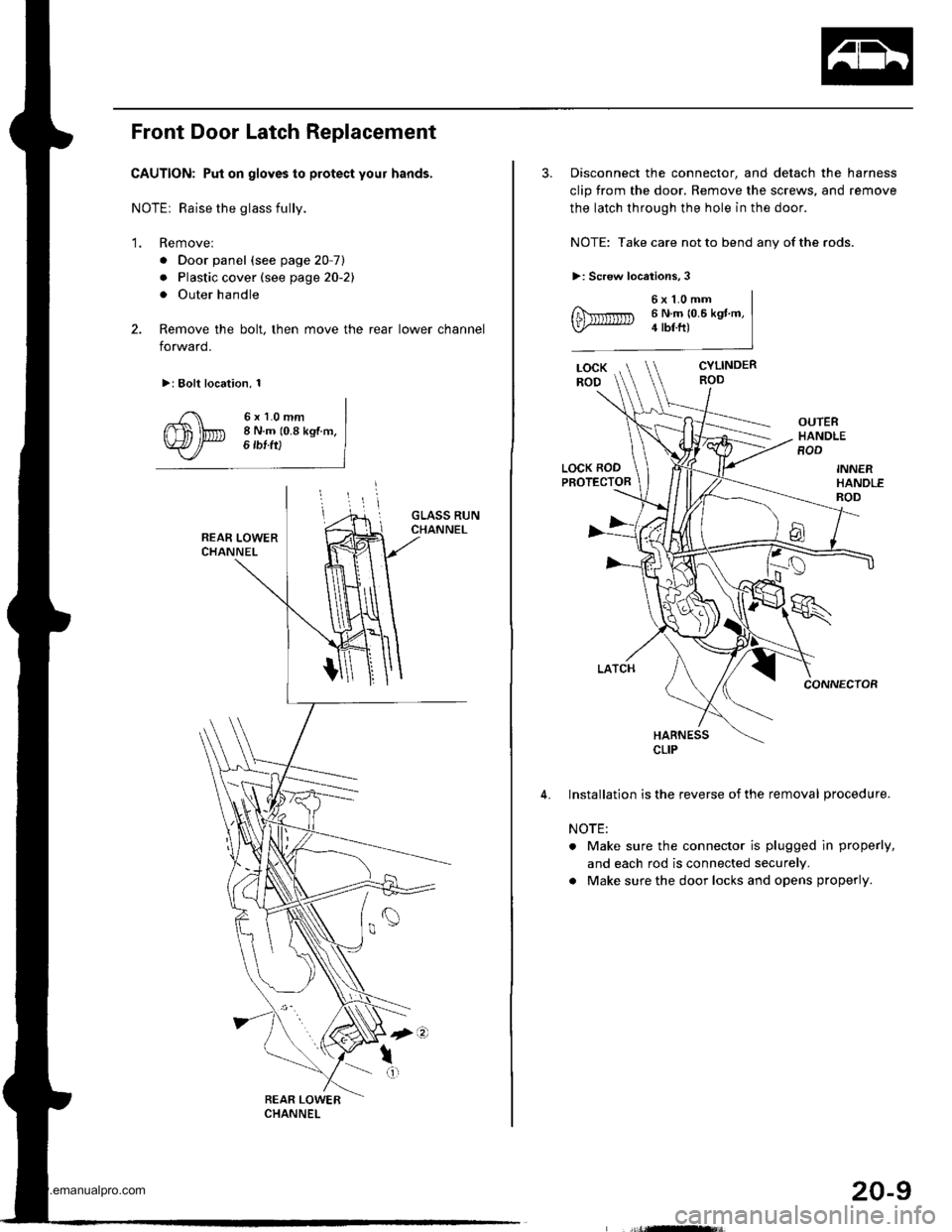
Front Door Latch Replacement
CAUTION: Put on gloves to protect your hands,
NOTEr Raise the glass fully.
'1. Remove:
. Door panel (see page 20-7)
. Plastic cover (see page 20-21
. Outer handle
2. Remove the bolt, then move the rear lower channel
forward.
>: Bolt location, 1
6xl.0mm8 N.m (0.8 kgf m,6 tbf ft)
3. Disconnect the connector, and detach the harness
clip from the door. Remove the screws, and remove
the latch through the hole in the door.
NOTE: Take care not to bend any of the rods.
>: Screw locations,3
6x1.0mm6 N.m 10.6 kgt m,4 tbf.ft)
CYLINDERROD
OUTERHANDLEROD
LOCK RODPROTECTOR
CONNECTOR
HARNESS
Installation is the reverse of the removal procedure.
NOTE:
. Make sure the connector is plugged in properly,
and each rod is connected securely.
a Make sure the door locks and opens properly.
CLIP
20-9
www.emanualpro.com
Page 993 of 1395
Doors
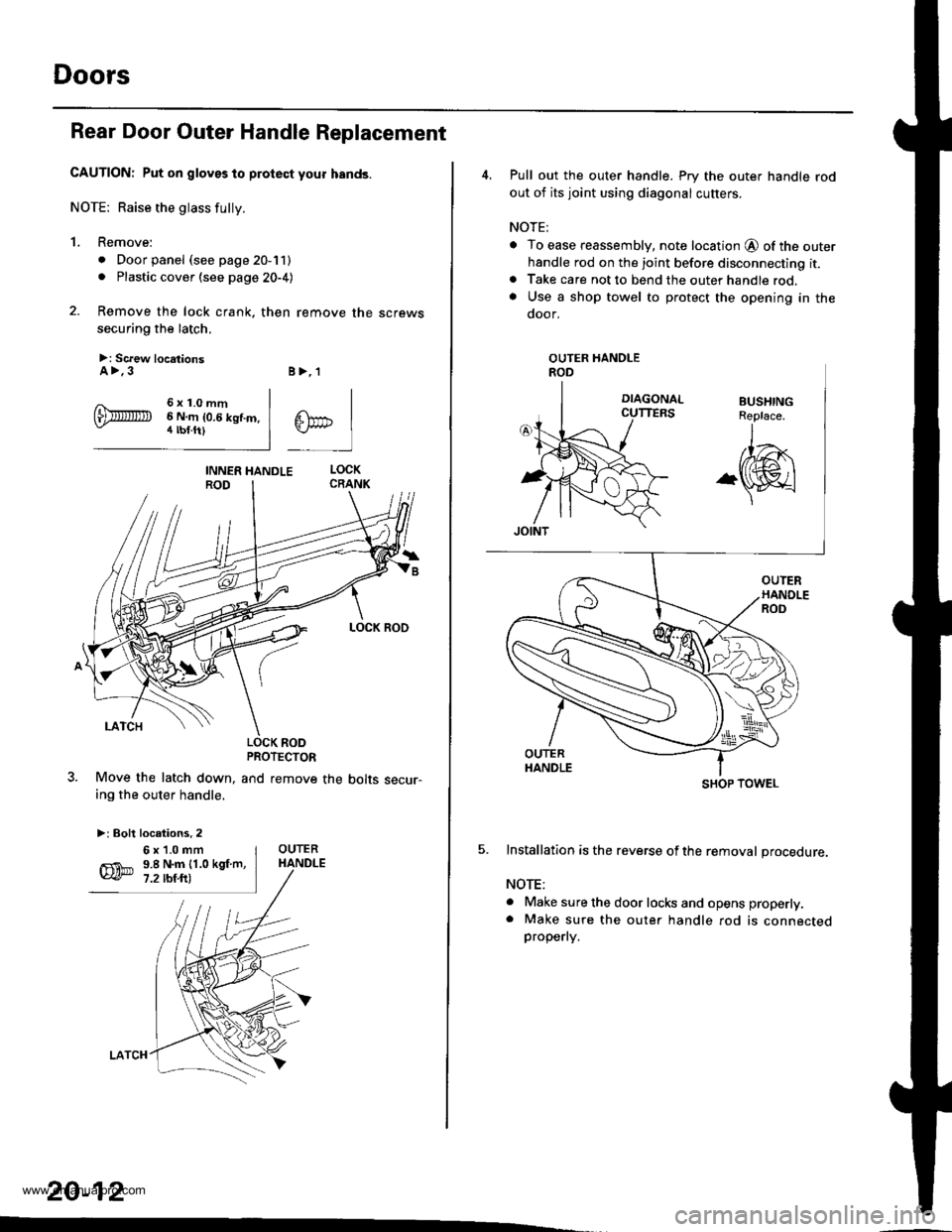
Rear Door Outer Handle Replacement
CAUTION: Put on gloves to protect your hands.
NOTE: Raise the glass fully.
1. Remove:
. Door panel (see page 20-11). Plastic cover (see page 20-4)
2. Remove the lock crank. then remove the screws
securing the latch.
>: Screw locationsA>.3
6x1.0mm6 N.m 10.6 kgf.m.4 tbf.ft)
B>,'l
^lPC tlTn-i I
LOCK RODPROTECTOR
and remove the bolts secur-Move the latch down,
ing the outer handle,
>: Bolt locations. 2
20-12
.
6x1.0mm9.8 N.m {1.0 kgf.m,7.2 rbf.ft)
4, Pull out the outer handle. Pry the outer handle rod
out of its joint using diagonal cutters.
NOTE;
o To ease reassembly, note location @ of the outerhandle rod on the joint before disconnecting it.. Take care not to bend the outer handle rod.. Use a shop towel to protect the opening in the
door.
5. Installation is the reverse ofthe removal procedure.
NOTE:
a Make sure the door locks and opens properly.. Make sure the oute. handle rod is connectedproperly.
OUTER HANDLEROD
SHOP TOWEL
www.emanualpro.com
Page 997 of 1395
Doors
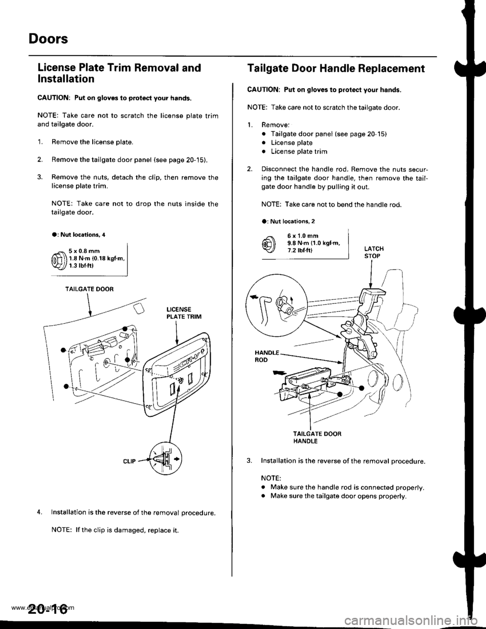
License Plate Trim Removal and
Installation
CAUTION: Put on gloves to prolest your hands.
NOTE: Take care not to scratch the license plate trim
and tailgate door.
'1. Remove the license olate.
2. Remove the tailgate door panel (see page 20-15).
3. Remove the nuts, detach the clip, then remove the
license olate trim.
NOTE: Take care not to drop the nuts inside the
tailgate door.
a: Nut loc.lions.4
5x0.8mm1.8Nm(0.18kgt.m.1.3 rbf.ft)
4. Installation is the reverse of the removal procedure.
NOTE: lf the clip is damaged, replace it.
20-16
TAILGATE DOOR
Tailgate Door Handle Replacement
CAUTION; Put on gloves to protecl your hands,
NOTE: Take care not to scratch the tailgate door.
1. Remove:
. Tailgate door panel (see page 20,15)
. License plate
. License plate trim
2. Disconnect the handle rod. Remove the nuts secur-
ing the tailgate door handle, then remove the tail-gate door handle by pulling it out.
NOTE: Take care not to bend the handle rod.
6x1.0mm9.8 N.m {1.0 kgtm,7.2 rbtft)
TAILGATE DOORHANDLE
Installation is the reverse of the removal procedure.
NOTE:
. Make sure the handle rod is connected properly.
. Make sure the tailgate door opens propedy.
a: Nut locations,2
,Is
www.emanualpro.com
Page 998 of 1395
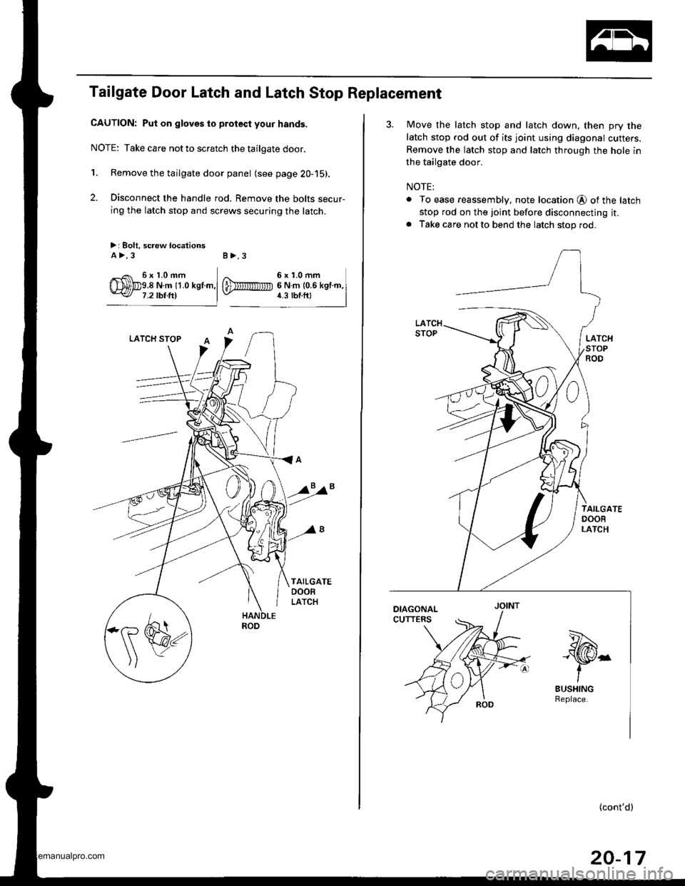
Tailgate Door Latch and Latch Stop Replacement
CAUTION: Put on gloves to protect your hands.
NOTE: Take care notto scratch the tailgate door.
'1. Remove the tailgate door panel (see page 20-15).
2. Disconnect the handle rod. Remove the bolts secur-
ing the latch stop and screws securing the latch.
>: Bolt, screw locationsA>,3 B>,3
6x1.0mm
3. Move the latch stop and latch down, then pry the
latch stop rod out of its joint using diagonal cutters.
Remove the latch stop and latch through the hole in
the tailgate door.
NOTE:
. To ease reassembly, note location @ of the latch
stop rod on the joint before disconnecting it.. Take care not to bend the latch stop rod.
''-t.-Ngta
-\S/r
tBUSHING
(cont'd)
20-17
www.emanualpro.com
Page 999 of 1395
Doors
Tailgate Door Latch and Latch Stop
Replacement (cont'd)
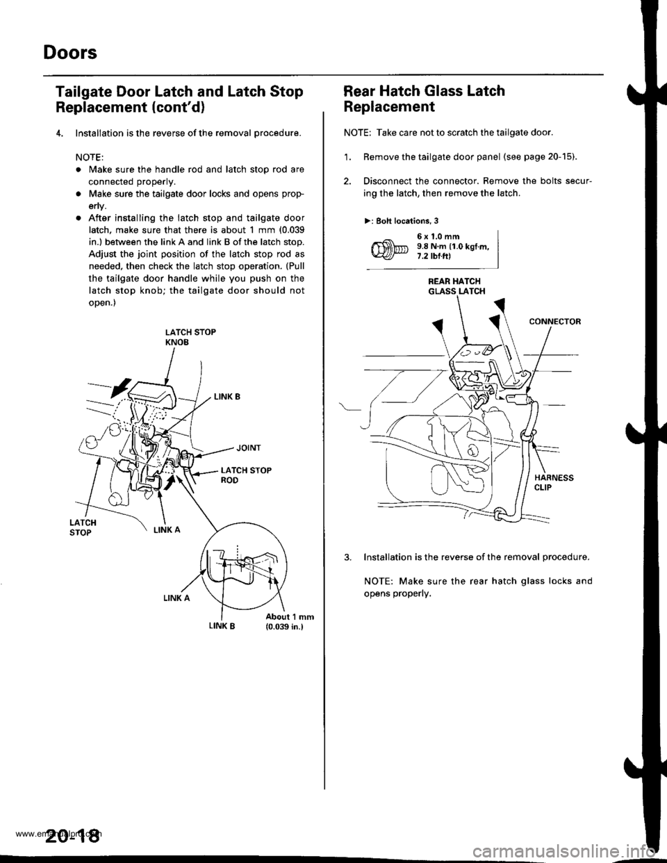
4. lnstallation is the reverse of the removal orocedure.
NOTE:
. Make sure the handle rod and latch stop rod are
connected properly.
a Make sure the tailgate door locks and opens prop-
env.
. After installing the latch stop and tailgate door
latch, make sure that there is about 1 mm {0.039
in.l between the link A and link B of the latch stop.
Adjust the joint position of the latch stop rod as
needed, then check the latch stop operation. (Pull
the tailgate door handle while you push on the
latch stop knob; the tailgate door should not
oDen.)
LATCH STOPKNOE
20-18
Rear Hatch Glass Latch
Replacement
NOTE: Take care not to scratch the tailgate door.
'1. Remove the tailgate door panel (seepage20-15).
2. Disconnect the connector. Remove the bolts secur-
ing the latch, then remove the latch.
>: Boh locations, 3
6x1.0mm9.8 N.m {1.0 kgI.m,7.2 tbl.Itl
REAR HATCHGLASS LATCH
3. Installation is the reverse of the removal procedure.
NOTE: Make sure the rear hatch glass locks and
opens properly.
www.emanualpro.com
Page 1000 of 1395
Rear Hatch Glass Lock Cylinder
Replacement
NOTE: Take care not to scratch the tailgate door.
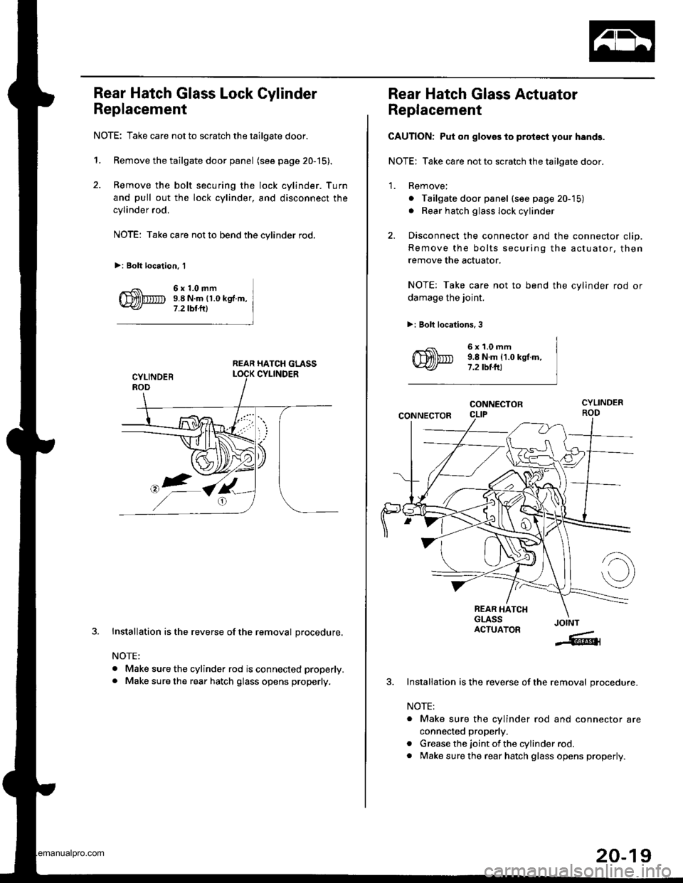
1. Remove the tailgate door panel (see page 20-15).
2. Remove the bolt securing the lock cylinder. Turn
and pull out the lock cylinder, and disconnect the
cylinder rod,
NOTE: Take care not to bend the cylinder rod.
>: Bolt location. 1
6x1.0mm9.8 N.m {1.0 kg .m,
7 .2 tbt.lll
REAR HATCH GLASS
J.Installation is the reverse of the removal procedure.
NOTE:
. Make sure the cylinder rod is connected properly.
. Make sure the rear hatch glass opens properly.
Rear Hatch Glass Actuator
Replacement
CAUTION: Put on gloves to protsct your hands.
NOTE: Take care not to scratch the tailgate door.
1. Remove;
o Tailgate door panel (see page 20-'15)
. Rear hatch glass lock cylinder
2. Disconnect the connector and the connector clip.
Remove the bolts securing the actuator, then
remove the actuator.
NOTE: Take care not to bend the cylinder rod or
damage the joint.
>: Bolt locations, 3
6x1.0mm9.8 N.m 11.0 kgt.m,7.2 tbt.ft)
CONNECTOR
CONNECTOR
REAR HATCHGLASSACTUATORJOINT
-6{
Installation is the reverse of the removal procedure.
NOTE:
. Make sure the cylinder rod and connector are
connected properly.
. Grease the joint of the cylinder rod.
. Make sure the rear hatch glass opens properly.
20-19
www.emanualpro.com
Page 1005 of 1395
Doors
(cont'd)
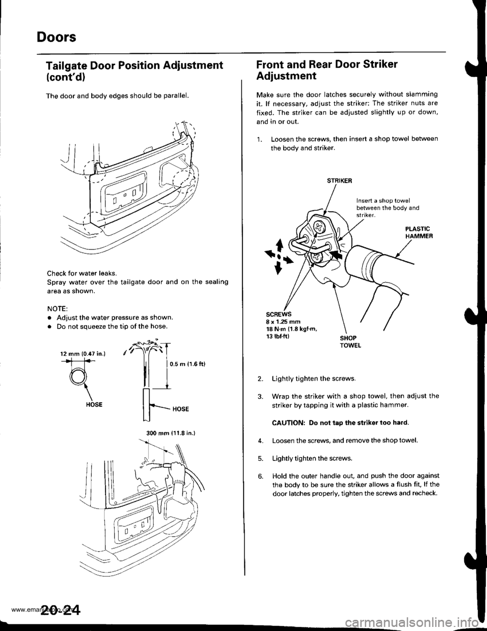
The door and body edges should be parallel.
Check for water leaks.
Spray water over the tailgate door and on the sealing
area as shown.
NOTE:
. Adjust the water pressure as shown.
. Do not squeeze the tip ofthe hose.
Tailgate Door Position Adiustment
-€*4
,'r)"C
II
0.5 m {1.6 ft}
20-24
l2 mm (0.47 in.).*1:]*
d3"1
HOSE
300 mm {11.8 in.l
Front and Rear Door Striker
Adjustment
Make sure the door latches securely without slamming
it, lf necessary, adjust the striker: The striker nuts are
fixed. The striker can be adjusted slightly up or down,
and in or out.
1. Loosen the screws, then insert a shop towel between
the body and striker.
Insert a shop towelbetween the body and
scREws8 x 1 .25 mm18 N.m (1.8 kgt.m,13 rbf.ft)
2.
J.
Lightly tighten the screws.
Wrap the striker with a shop towel, then adjust the
striker by tapping it with a plastic hammer.
CAUTION: Do not tap the striksr loo hard.
Loosen the screws. and remove the shop towel.
Lightly tighten the screws.
Hold the outer handle out, and push the door against
the body to be sure the striker allows a flush fit, lf the
door latches properly. tighten the screws and recheck.
4.
5.
6.
STRIKER
www.emanualpro.com
Page 1006 of 1395
Tailgate Door Striker Adjustment
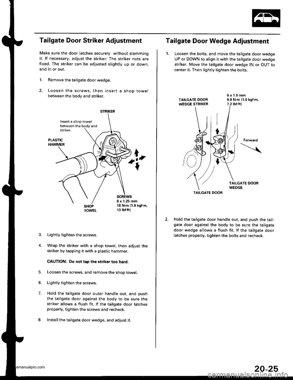
Make sure the door latches securely without slamming
it. lf necessary, adjust the striker: The striker nuts are
fixed. The striker can be adjusted slightly up or down,
and in or out.
1. Remove the tailgate door wedge.
2. Loosen the screws, then insert a shop towel
between the body and striker.
8 x 1.25 mm18 N.m (1.8 kgf.m,r 3 tbf.ft)
1.
4.
Lightly tighten the screws.
Wrap the striker with a shop towel, then adjust the
striker by tapping it with a plastic hammer.
CAUTION: Do not tap the striker too hard.
Loosen lhe screws, and remove the shop towel.
Lightly tighten the screws.
Hold the tailgate door outer handle out, and push
the tailgate door against the body to be sure thestriker allows a flush fit. lf the tailgate door latchesproperly, tighten the screws and recheck.
Install the tailgate door wedge, and adjust it.
STRIKER
Insen a shoptowelbetween the body and
Tailgate Door Wedge Adjustment
1. Loosen the bolts, and move the tailgate door wedge
UP or DOWN to align it with the tailgate door wedge
striker. Move the tailgate door wedge lN or OUT to
center it. Then lightly tighten the bolts.
TAILGATE OOOR
Hold the tailgate door handle out, and push the tail-gate door against the body to be sure the tailgate
door wedge allows a flush fit. lf the tailgate door
latches properly, tighten the bolts and recheck.
Forward
20-25
www.emanualpro.com
Page 1025 of 1395
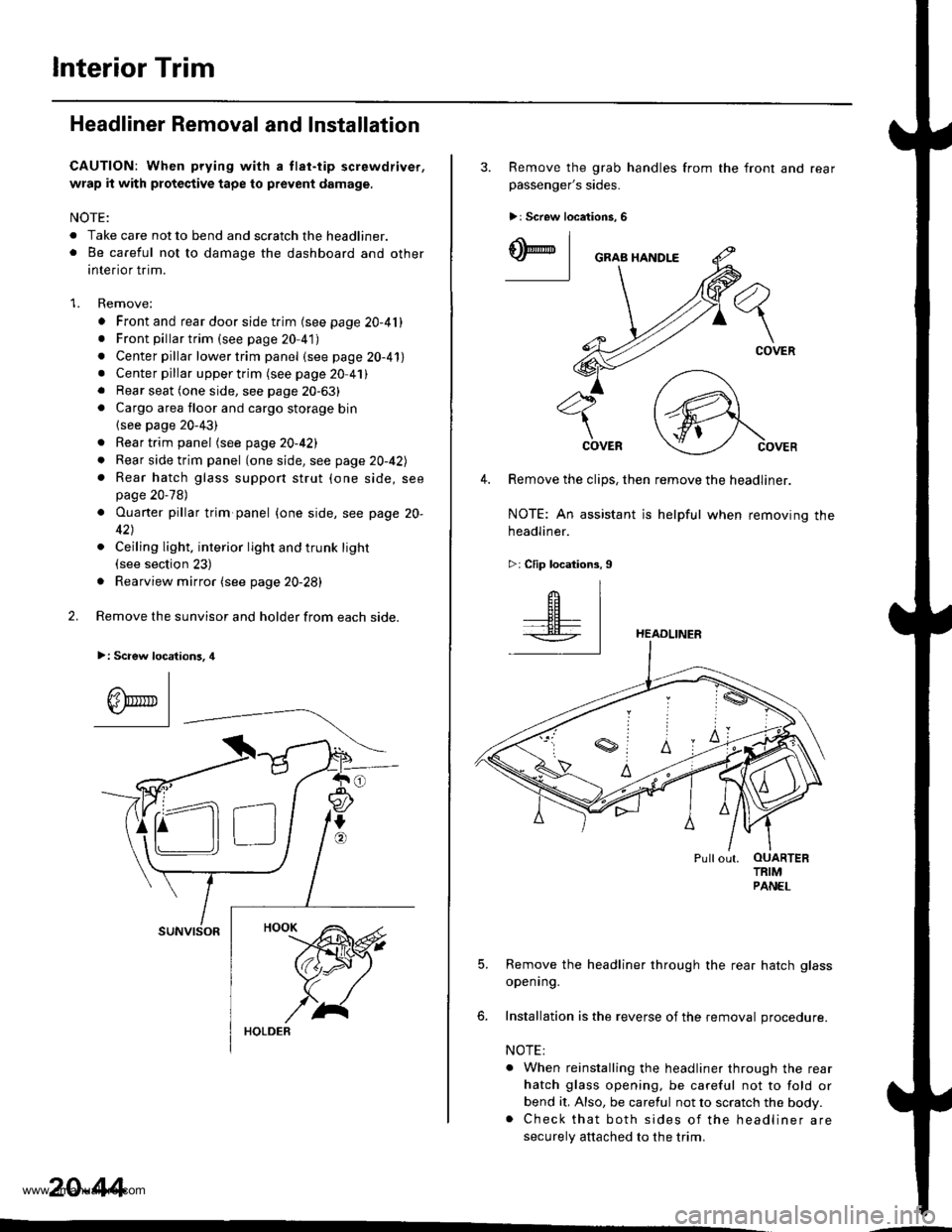
lnterior Trim
Headliner Removal and Installation
CAUTION: When prying with a tlat-tip screwdriver,
wrap it with protective tape to prevent damage.
NOTE:
. Take care not to bend and scratch the headliner.o Be careful not to damage the dashboard and other
interior trim.
1. Remove:
. Front and rear door side trim (see page 20-41). Front pillartrim (see page 20-41)
. Center pillar lower trim panel (see page 20-41). Center pillar upper trim (see page 20 41). Rear seat (one side, see page 20-63). Cargo area floor and cargo storage bin
{see page 20-43)
. Rear trim panel (see page 20-421
. Rear side trim panel (oneside, see page 20-42l,
. Rear hatch glass support strut (one side, seepage 20-78)
. Ouaner pillar trim panel {one side, see page 20-
42)
. Ceiling light, interior light and trunk light(see section 23)
. Rearview mirror (see page 20-28)
2. Remove the sunvisor and holder from each side.
>: Scaew location3, 4
I
A\"r- |Yr* || -
suNvtsoR
20-44
3. Remove the grab handles from
passenger's sides.
>r Screw locations, 6
the front and rear
ry_l
COVER
4. Remove the clips, then remove the headliner.
NOTE: An assistant is helpful when removing the
headliner.
>: Clip locations,9
HEADLINER
Pullout. OUARTERTRIMPANEL
5. Remove the headliner through the rear hatch glass
openrng.
6. Installation is the reverse of the removal procedure.
NOTE:
. When reinstalling the headliner through the rear
hatch glass opening, be careful not to fold or
bend it, Also, be careful not to scratch the body.. Check that both sides of the headliner are
securely attached to the trim.
www.emanualpro.com
Page 1041 of 1395
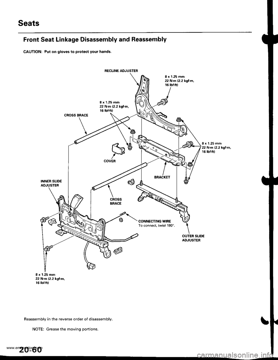
Seats
RECUNE ADJUSTER
Front Seat Linkage Disassembly and Reassembly
CAUTION: Put on gloves to protect your hands.
8 x 1 .25 mm22 N.m 12.2 kgl.m,16 tbf.fi)
8 x 1.25 mm22 N.m 12.2 kd-m,16 tbtf0
CROSS BRACE
8 x 1.25 mm22 N.m 12.2 kgl.m,16 tbf.f0
INNER SLIDEADJUSTER
8 x 1.25 mm22 N.rn l.2.2 kgl-m,16 rbr.ft)
CONNECTING WIRETo connect, twist 180".
cRossBRACE
OUTER SLIDEAOJUSTER
Reassembly in the reverse order of disassembly.
NOTE: Grease the moving portions.
20-60
www.emanualpro.com