Gear position HONDA CR-V 1999 RD1-RD3 / 1.G Manual Online
[x] Cancel search | Manufacturer: HONDA, Model Year: 1999, Model line: CR-V, Model: HONDA CR-V 1999 RD1-RD3 / 1.GPages: 1395, PDF Size: 35.62 MB
Page 779 of 1395

26. Connect the vehicle speed sensor (VSS). the coun-
tershaft speed sensor. and the A,/T gear position
switch connectors,
VEHICLE SPEEO
SPEED SENSOACO'{NECTOR
Connect the lock-up control solenoid valve connec-
tor, then install the harness clamp on the clamp
bracket.
HARNESS CI-AMP
27.
RADIATOR HOSECLAMP
TRANSMISSIONGROUND CAB1ITERMINAL
LOCK-UP OONTROLSOLENOID VALVECONNECTOR
6x1.0mm12 N'm (1.2 kgi.m,8.? tbtftl
28.
29.
Instail the transmission ground cable terminal on
the transmission hanger, and install the radiator
hose clamp on the transmission hanger,
Connect the starter cables to the starter, and install
the harness clamD on the clamD bracket. Make sure
the crimped side of the starter cable ring terminal is
facing out.
STARTEBCABLE
STARTER CAAtf,
Install the air cleaner housing assembly and the
intake air duct.
Refill the transmission with ATF (see page 14-161).
Connect the battery positive terminal and negative
terminal.
Set the parking brake, Start the engine, and shift the
transmission through all gears three times.
Check the shift cable adjustment (see page 14-271]-.
Check the tront wheel alignment and adjust it if
needed (see section 18).
Let the engine reach normal operating temperature
(the radiator fan comes on) with the transmission in
E or N position, then turn it off and check the ATF
level {see page 14-160).
Perform a road test (see page 14-157 and 14-158).
30.
31.
34.
CLAMP BRACKET
37.
14-263
www.emanualpro.com
Page 788 of 1395
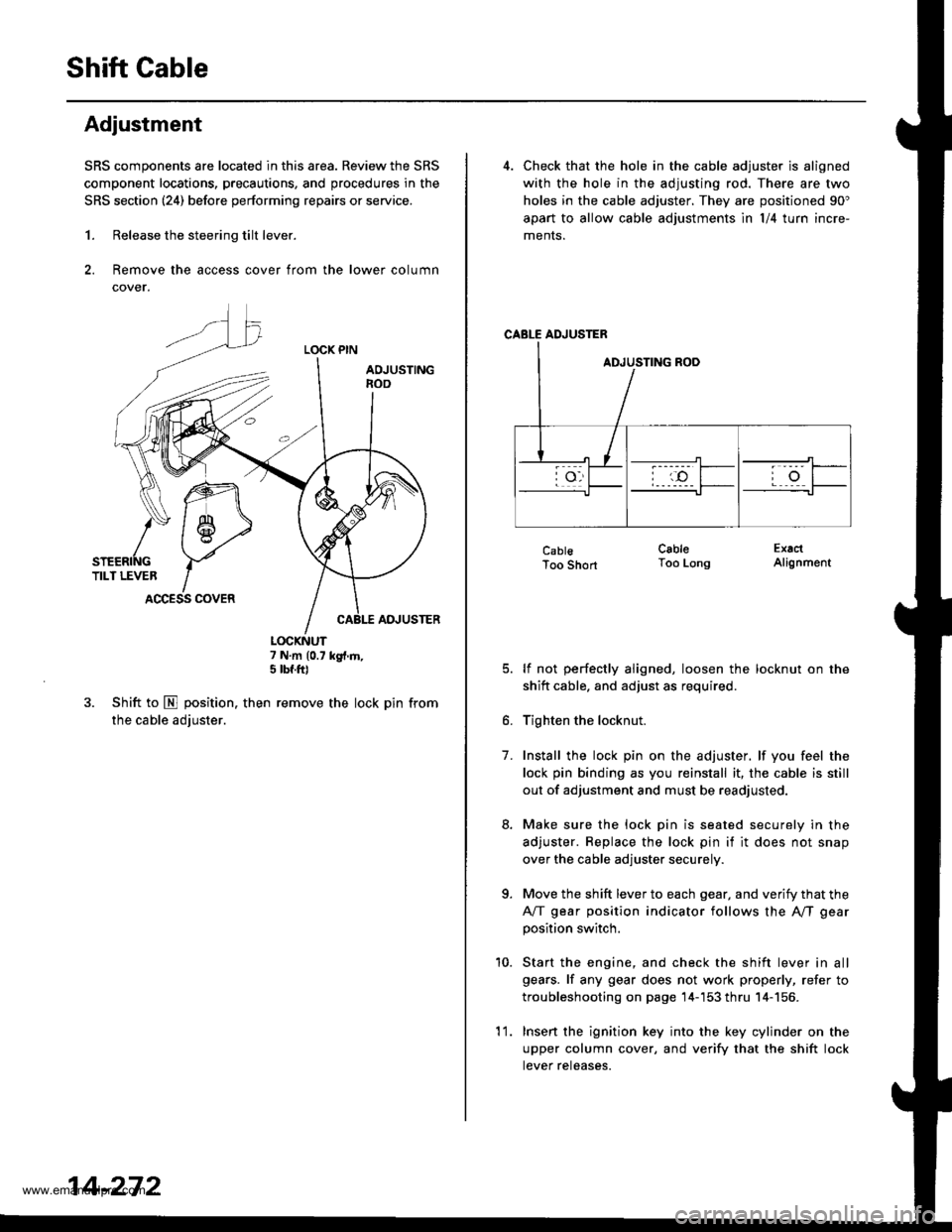
Shift Gable
Adjustment
SRS components are located in this area. Review the SRS
component locations, precautions, and procedures in the
SRS section (241 before performing repairs or service.
1. Release the steering tilt lever.
2. Remove the access cover from the lower column
cover.
LOCK PIN
AOJUSTINGnoo
ADJUSTER
7 N.m (0.7 kg{.m,5 tbf.ft)
3. Shift to E position. then remove the lock pin from
the cable adjuster.
K\ffi
/* 1 6-,>
snenrftc YTILT LEVER IACCESS COVER
14-272
'l 1.
4. Check that the hole in the cable adjuster is aligned
with the hole in the adjusting rod. There are two
holes in the cable adjuster. They are positioned 90"
apart to allow cable adjustments ln l/4 turn incre-
ments.
CABLE ADJUSTER
CablsToo Short
lf not perfectly aligned, loosen the locknut on the
shitt cable. and adjust as required.
Tighten the locknut.
Install the lock pin on the adjuster. lf you feel the
lock pin binding as you reinstall it, the cable is still
out of adjustment and must be readjusted.
Make sure the lock pin is seated securely in the
adjuster. Replace the lock pin if it does not snap
over the cable adjuster securely.
Move the shift lever to each gear, and verify that the
A/T gear position indicator follows the A"/T gear
position switch.
Start the engine, and check the shift lever in all
gears. lf any gear does not work properly, refer to
troubleshooting on page 14-'153 thru 14-156.
Insert the ignition key into the key cylinder on the
upper column cover, and verify that the shift lock
tever reteases.
CableToo LongExactAlignment
7.
a
10.
www.emanualpro.com
Page 800 of 1395
Real-time 4WD-Dual Pump System
Troubleshooting (Automatic Transmissionl
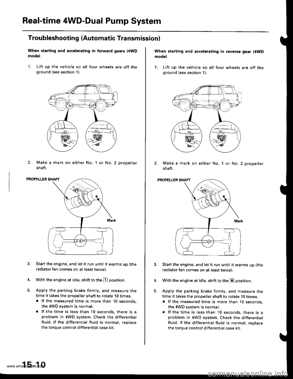
When starting and accelerating in forward gesrs {4WDmodel
1. Lift up the vehicle so all four wheels are off theground (see section 1).
2. Make a mark on either No.
shaft.
'I or No.2 propeller
PROPELLER SHAFT
Start the engine, and let it run until it warms up (the
radiator fan comes on at least twice).
With the engine at idle. shift to the E position.
Apply the parking brake firmly. and measure thetime it takes the propeller shaft to rotate 10 times.. lf the measured time is more than 10 seconds,
the 4WD system is normal.
. lf the time is less than 10 seconds, there is aproblem in 4WD system. Check the differential
fluid. lf the differential fluid is normal, replace
the torque control differential case kit.
15-10
When starting and accelerating in revGrsg gear {4WDmodel
1. Lift up the vehicle so all four wheels are off theground (see section 1).
Make a mark on either No.
shaft.
1 or No. 2 propeller
PROPELLER SHAFT
Start the engine. and let it run until it warms up (the
radiator fan comes on at least twicei.
With the engine at idle, shift to the E position.
Apply the parking brake firmly, and measure the
time it takes the proDeller shaft to rotate 10 times,. lf the measured time is more than 10 seconds,
the 4WD system js normal.. lf the time is less than 10 seconds, there is aproblem in 4WD system. Check the differential
fluid. lf the differential fluid is normal, reolace
the torque control differential case kit.
www.emanualpro.com
Page 857 of 1395
Inspection and Adjustment
Steering Operation
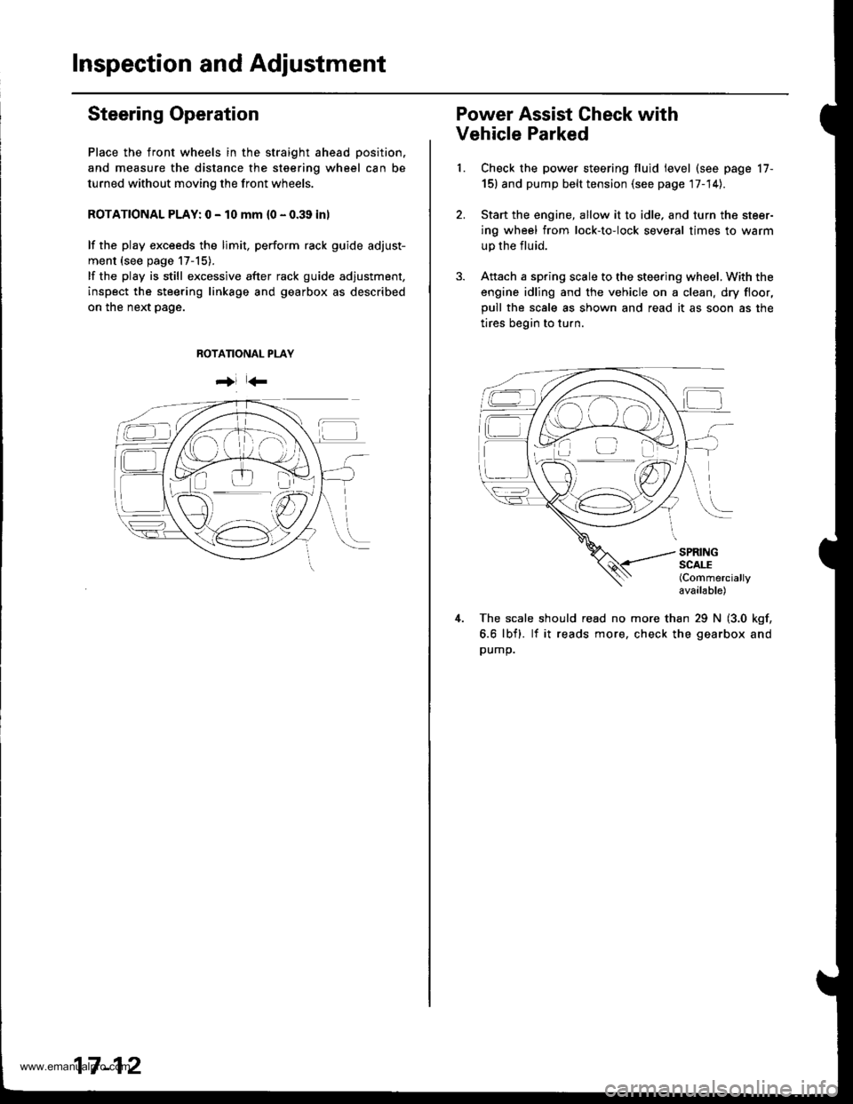
Place the front wheels in the straight ahead position.
and measure the distance the steering wheel can be
turned without moving the front wheels.
ROTATIONAL PLAY: 0 - 10 mm (0 - 0.39 inl
lf the play exceeds the limit, perform rack guide adjust-
ment (see page 17-15).
lf the play is still excessive after rack guide adjustment,
inspect the steering linkage and gearbox as described
on the next page.
ROTANONAL PLAY
+i r
17-12
Power Assist Check with
Vehicle Parked
1. Check the power steering fluid level (see page 17-
15) and pump belt tension (see page 17-14).
2. Start the engine, allow it to idle, and turn the steer-
ing wheel from lock-toiock several times to warm
up the fluid.
3. Aftach a spring scale to the steering wheel, With the
engine idling and the vehicle on a clean. dry floor,
pull the scale as shown and read it as soon as the
tires begin to turn.
SPRINGSCALE(Commercially
available)
The scale should read no more than 29 N (3.0 kgf,
6.6 lbfl. lf it reads more, check the gearbox and
oumo.
f::1-tE
www.emanualpro.com
Page 860 of 1395
Rack Guide Adjustment
1.
6.
7.
5.
4.
Set the wheels in the straight ahead position.
Loosen the rack guide screw locknut with the spe-
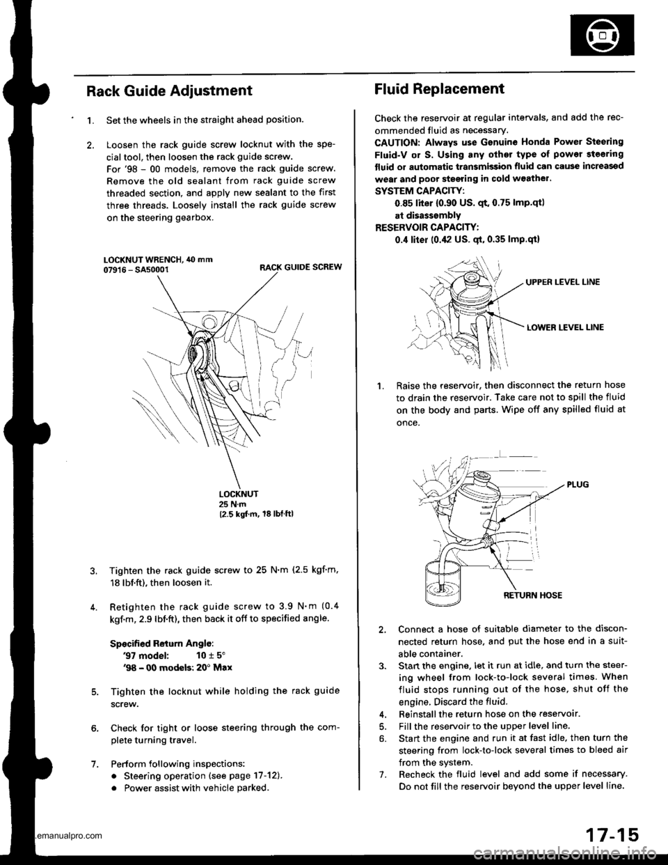
cialtool, then loosen the rack guide screw.
For'98 - 00 models, remove the rack guide screw.
Remove the old sealant from rack guide screw
threaded section, and apply new sealant to the first
three threads. Loosely install the rack guide screw
on the steering gearbox.
RACK GUIDE SCREW
LOCKNUT25 N.m
12.5 kgt m, 18lbtftl
Tighten the rack guide screw to 25 N.m (2.5 kgf'm,
18 lbf.ft), then loosen it.
Retighten the rack guide screw to 3.9 N'm (0.4
kgf.m, 2.9 lbf.ft), then back it off to specified angle.
Specified Return Anglo:
37 model: 10 r 5"'98 - 00 modeb: 20' Max
Tighten the locknut while holding the rack guide
screw.
Check for tight or loose steering through the com-
plete turning travel.
Perform following inspections:
. Steering operation (see page 17-12).
. Power assist with vehicle parked
Fluid Replacement
Check the reseryoir at regular intervals, and add the rec-
ommended fluid as necessary.
CAUTION: Always use Gsnuine Honda Power Steering
Fluid-V or S. Using any other type of power steering
tluid or automatic transmission fluid can cause increassd
wear and poor steering in cold w3athel.
SYSTEM CAPACITY:
0.85 liter {0.90 US. qt. 0.75 lmp.qtl
at disasssmbly
RESERVOIR CAPACITY:
0.,1 liter (0.42 US. gt, 0.35 lmp.qi)
UPPEN LEVEL LINE
LOWER LEVEL LINE
1.Raise the reservoir. then disconnect the return hose
to drain the reservoir. Take care not to spill the fluid
on the body and parts. Wipe off any spilled fluid at
once.
2, Connect a hose of suitable diameter to the discon-
nected return hose, and put the hose end in a suit-
able container.
3. Stan the engine. let it run at idle, and turn the steer-
ing wheel from lock-to-lock several times. When
fluid stops running out of the hose, shut off the
engine. Discard the fluid.
4. Beinstallthe return hose on the reservoar.
5. Fill the reservoir to the upper level line,
6. Start the engine and run it at fast idle. then turn the
steering from lock-to-lock several times to bleed air
from the system.
7. Recheck the fluid level and add some if necessary.
Do not fill the reservoir beyond the upper level line.
www.emanualpro.com
Page 868 of 1395
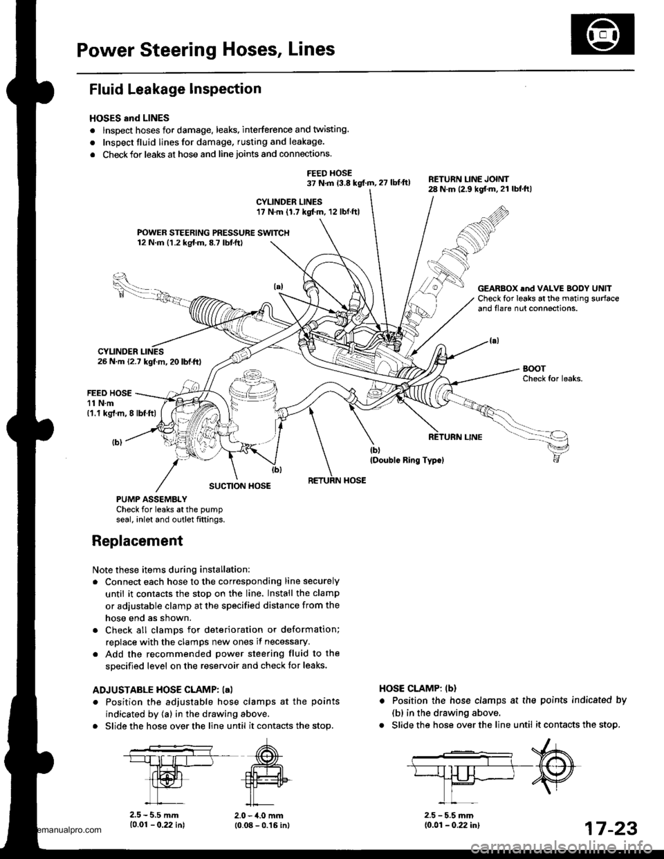
Power Steering Hoses, Lines
Fluid Leakage Inspection
HOSES and LINES
. lnspect hoses for damage. leaks. interference and twisting
. Inspect fluid linesfor damage, rusting and leakage.
. Check for leaks at hose and line joints and connections.
FEED HOSE37 N.m 13.8 kgf.m, 27 lbtft)RETURN LINE JOINT28 N.m (2.9 kgf.m.21 lbf.ftl
CYLINDER LINES17 N.m (1.7 kgf.m. 12 lbf.ftl
FOWER STEERING PRESSURE SWITCH12 N.m (1.2 kgf.m,8.7 lbtft)
26 N.m (2.7 kgf.m, 20 lbf.ft)
GEARBOX .nd VALVE BODY UNllCheck for leaks at the mating surfaceand flare nut connections.
CYLINDER
FEED HOSE11 N.m('1.1 kgt.m, 8 lbf.ftl
SUCTION HOSE
PUMP ASSEMBLYCheck for leaks atthe pump
seal. inlet and outlet fittings.
Note these items during installation:
. Connect each hose to the corresponding line securely
until it contacts the stop on the line. Install the clamp
or adjustable clamp at the specified distance from the
hose end as shown.
. Check all clamDs for deterioration or deformation;
replace with the clamps new ones if necessary.
. Add the recommended power steering fluid to the
specified level on the reservoir and check for leaks.
ADJUSTABLE HOSE CLAMP: la)
. Position the adjustable hose clamps at the points
indicated by (a) in the drawing above.
. Slide the hose over the line until it contacts the stop.
HOSE CLAMP: lbl
. Position the hose clamps at the
(b) in the drawing above.
. Slide the hose over the line until
Replacement
10.01 - 0.22 in)
points indicatsd by
it contacts the stop,
2.0 - 4.0 mm10.08 - 0.16 inl2.5 - 5.5 mm{0.01 - 0.22 in}17 -23
www.emanualpro.com
Page 882 of 1395
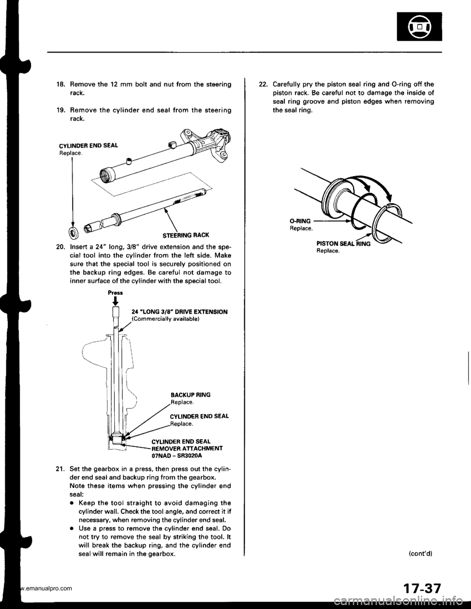
18. Remove the 12 mm bolt and nut trom the stsering
rack,
19. Remove the cylinder end seal from the steering
racK.
20. lnsert a 24" long,3/8" drive extension and the spe-
cial tool into the cvlinder from the left side. Make
sure that the special tool is securely positioned on
the backup ring edges. Be careful not damage to
inner surface of the cylinder with the special tool.
Replace.
I
I
I
CI
24 'LONG 3/8' DRIVE EXTENSION(Commerciallv available)
BACKUP RING
CYLINDER END SEAL
CYLINDER END SEALREMOVER ATTACHMENT07NAD - SR3020A
21.Set the gearbox in a press, then press out the cylin-
der end seal and backup ring from the gearbox.
Note these items when pressing the cylinder end
seat:
. Keep the tool straight to avoid damaging the
cylinder wall. Check the tool angle, and correct it if
necessary, when removing the cylinder end seal.
. Use a press to remove the cylinder end seal. Do
not try to remove the seal by striking the tool. lt
will break the backup ring, and the cylinder end
sealwill remain in the gearbox.
Prass
22. Carelully pry the piston sesl ring and O-ring off the
piston rack. Be careful not to damage the inside of
seal ring groove and piston edges when removing
the seal ring.
Replaco.
(cont'dl
17-37
www.emanualpro.com
Page 889 of 1395
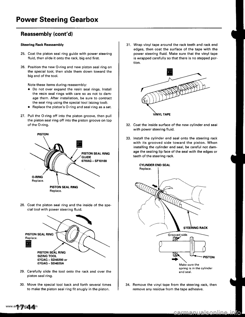
Power Steering Gearbox
Reassembly (cont'dl
Stecring Rack R8assembly
25. Coat the piston seal ring guide with power steering
fluid, then slide it onto the rack, big end first.
26. Position the new O-ring and new piston seal ring on
the sDecial tool, then slide them down toward the
big end of the tool.
Note these items during reassembly:
a Do not over expand the resin seal rings. Install
the resin seal rings with care so as not to dam-
age them. After installation, be sure to contract
the seal ring using the special tool (sizing tool).
a Replace the piston's O-ring and seal ring as a set.
27. Pull rhe O-ring off into the piston groove, then pull
the piston seal ring off into the piston groove on top
of the O-ring.
Coat the piston seal ring and the inside of the spe-
cial tool with power steering fluid.
07GAG - SO4O200 orOTGAG - SD'()2OA
Carefully slide the tool onto the rack and over thepiston seal ring.
Move the special tool back and fonh several times
to make the piston seal ring fit snugly in the piston.
24.
PISTONReplace
E
30.
PISTON
17-44
31. Wrap vinyl tape around the rack teeth and rack end
edges, then coat the surface of the tape with the
power steering fluid. Make sure that the vinyl tape
is wrapped carefully so that there is no stepped por-
tion.
Coat the inside surface of the new cvlinder end
with power steering fluid.
Install the cylinder end seal onto the steering rack
with its grooved side toward the piston. When
installing the cylinder end seal, be careful not dam-
age the sealing lip face of the seal with the edges or
teeth of the steering rack.
CYLINDER END SEAL
Make sure thespring is in lhe cylindereno seal
Remove the vinyl tape from the steering rack, then
remove any residue from the tape adhesive.
www.emanualpro.com
Page 891 of 1395
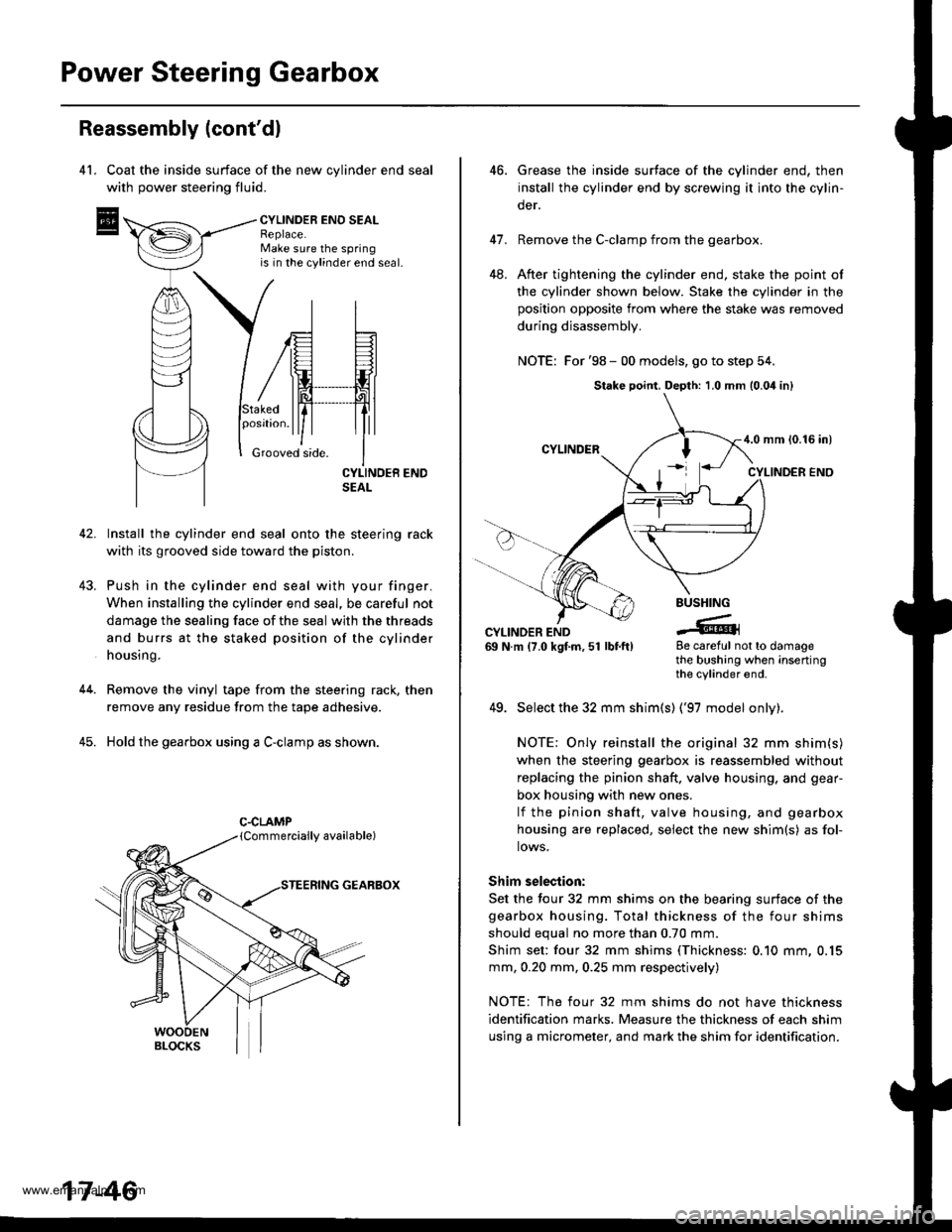
Power Steering Gearbox
Reassembly (cont'dl
4l. Coat the inside surface of the new cvlinder end seal
with power steering fluid.
CYLINDEB ENO SEALReplace.Make sure the springis in the cylinder end seal.
43.
Stakedposrtron.
Grooved side.
42. Install the cylinder end seal onto the steering rack
with its grooved side toward the piston.
Push in the cylinder end seal with your finger.
When installing the cylinder end seal, be careful not
damage the sealing face of the seal with the threads
and burrs at the staked position of the cylinder
housing.
Remove the vinyl tape from the steering rack, then
remove any residue from the tape adhesive.
Hold the gearbox using a C-clamp as shown.
GEARBOX
44.
45.
C.CLAMP
17-46
46.Grease the inside surtace of the cylinder end, then
install the cylinder end by screwing it into the cylin-
der.
Remove the C-clamp from the gearbox.
After tightening the cylinder end, stake the point of
the cylinder shown below. Stake the cylinder in the
position opposite from where the stake was removed
during disassembly,
NOTE: For '98 - 00 models, go to step 54.
41.
48.
BUSHING
-tGCYLINDER END69 N.m (7.0 kgf.m,51 lbtft)8e careful not to damagethe bushing when insertingthe cylinder end.
49. Select the 32 mm shim(s) ('97 model onlv).
NOTE: Only reinstall the original 32 mm shim(s)
when the steering gearbox is reassembled without
replacing the pinion shaft. valve housing, and gear-
box housing with new ones.
lf the pinion shaft, valve housing, and gearbox
housing are replaced, select the new shim{s) as fol-
lows.
Shim selection:
Set the four 32 mm shims on the bearing surface of the
gearbox housing. Total thickness of the four shims
should equal no more than 0.70 mm.
Shim set: four 32 mm shims (Thickness: 0.10 mm, 0.15
mm, 0.20 mm, 0.25 mm respectively)
NOTE: The four 32 mm shims do not have thickness
identification marks. Measure the thickness of each shim
using a micrometer, and mark the shim for identification.
Stake point, Depth: 1,0 mm (0.04 inl
4.0 mm {0.16 in)
www.emanualpro.com
Page 892 of 1395
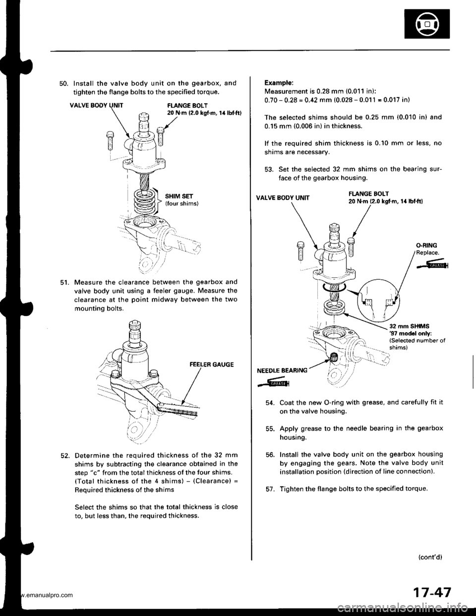
50. Install the valve body unit on the gearbox. and
tighten the flange bolts to the specified torque.
VALVE BODYFLANGE BOLT20 N.m 12.0 kgt.m, 14lbtft)
ct.
SHIM SET(four shims)
Measure the clearance between the gearbox and
valve body unit using a feeler gauge. Measure the
clearance at the poinl midway between the two
mounting bolts.
GAUGE
Determine the required thickness of the 32 mm
shims by subtracting the clearance obtained in the
step "c" from the total thickness of the four shims.
(Total thickness of the 4 shims) - (Clearance) =
Reouired thickness of the shims
Select the shims so that the total thickness is close
to, but less than, the required thickness.
Example:
Measurement is 0.28 mm (0.011 in);
0.70-0.28=0.42 mm (0.028-0.011 = 0.017 in)
The selected shims should be 0,25 mm (0.010 inl and
0.15 mm (0.006 in) in thickness.
lf the required shim thickness is 0.10 mm or less, no
shrms are necessary.
53. Set the selected 32 mm shims on the bearing sur-
face of the gearbox housing.
VALVE BODY UNITla lbl.frl
Coat the new O-ring with grease, and carefully fit it
on the valve housing.
Apply grease to the needle bearing in the gearbox
housing.
Install the valve body unit on the gearbox housing
by engaging the gears. Note the valve body unit
installation position (direction of line connection).
Tighten the flange bolts to the specified torque.
(cont'd)
FLANGE BOLT20 N.m (2.0 kgf.m,
/a)E?
E
O.RINGReplace.
-6{
NEEDLE BEARING
-6lr
54.
56.
57.
17-47
www.emanualpro.com