22-26 HONDA CR-V 1999 RD1-RD3 / 1.G Workshop Manual
[x] Cancel search | Manufacturer: HONDA, Model Year: 1999, Model line: CR-V, Model: HONDA CR-V 1999 RD1-RD3 / 1.GPages: 1395, PDF Size: 35.62 MB
Page 674 of 1395

Road Test
(cont'd)
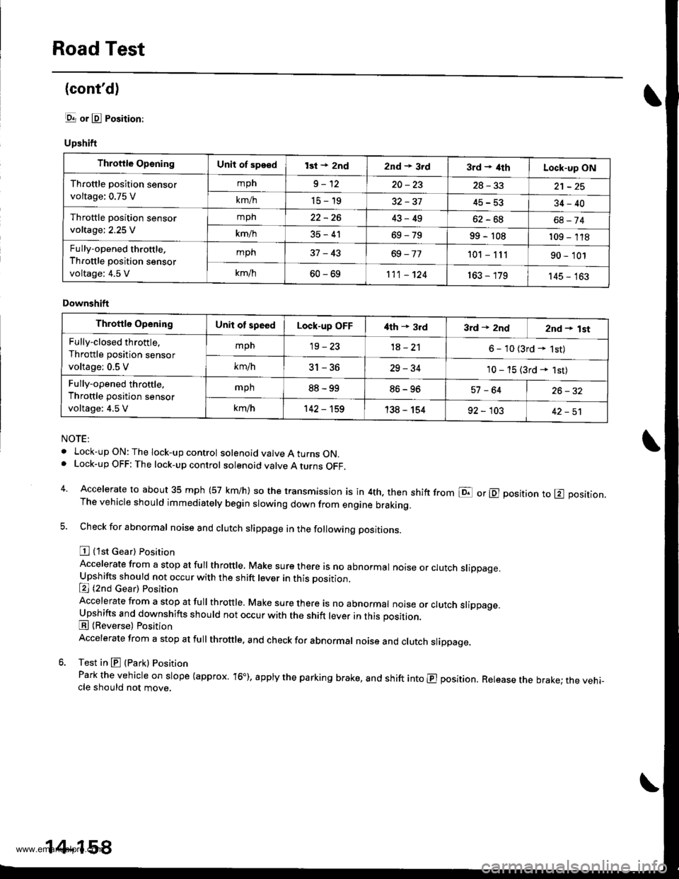
lgrr or E Position:
Upshift
NOTE:
. Lock-upON:The lock-up control solenoid valve A turns ON.. Lock-up OFF: The lock-up control solenoid valve A turns OFF.
4. Accelerate to about 35 mph (57 km/h) so the transmission is in 4th. then shift from E or E position to E position.The vehicle should immediately begin slowing down from engine braking.
5. Check for abnormal noise and clutch slippage in the following positions.
E {1st Gear) Position
Accelerate from a stop at full throttle, Make sure there is no abnormal noise or clutch slippage.Upshifts should not occur with the shift lever in this position.
E (2nd cear) Position
Accelerate from a stop at fuI throttre. Make sure there is no abnormar noise or crutch srippage.Upshifts and downshifts should not occur with the shift lever in this position.
E (Reverse) Position
Accelerate from a stop at full throttle. and check for abnormal noise and clutch slippage.
6. Test in E (Park) Position
Park the vehicle on slope (approx. 16"), apply the parking brake, and shift into E position. Release the brake; the vehi-cle should not move.
Throftle OpsningUnit of sps€dlsi + 2nd2nd * 3rd3rd + ilthLock-up ON
Throttle position sensor
voltage: 0.75 V
mph9-1220-2328-33
km/h15-1945-5334-40
Throttle position sensor
voltage; 2.25 V
mph22-2643-49oz - ott68-74
km/h35-4169-7999 - 108109 - 118
Fully-opened throttle,
Throttle position sensor
voltage: 4.5 V
mph37-43101 - 11190 - 101
k-/h60-69111 - 124163 - 179145 - 163
Downshift
Throttle OpeningUnit ot speedLock-up OFFi{th + 3rd3rd * 2ndznd + lst
Fully-closed throttle,
Throttle position sensor
voltage; 0.5 V
mpn19-231A - 2'l6 - 10 {3rd - 1st)
km/h5t-5D29-3410 - 15 (3rd * 1st)
Fully-opened throttle,
Throttle position sensor
voltage: 4,5 V
mph88-9986-9657 -6426-32
km/h142 - 't59138 - 15492 - 10342-51
14-158
www.emanualpro.com
Page 1117 of 1395

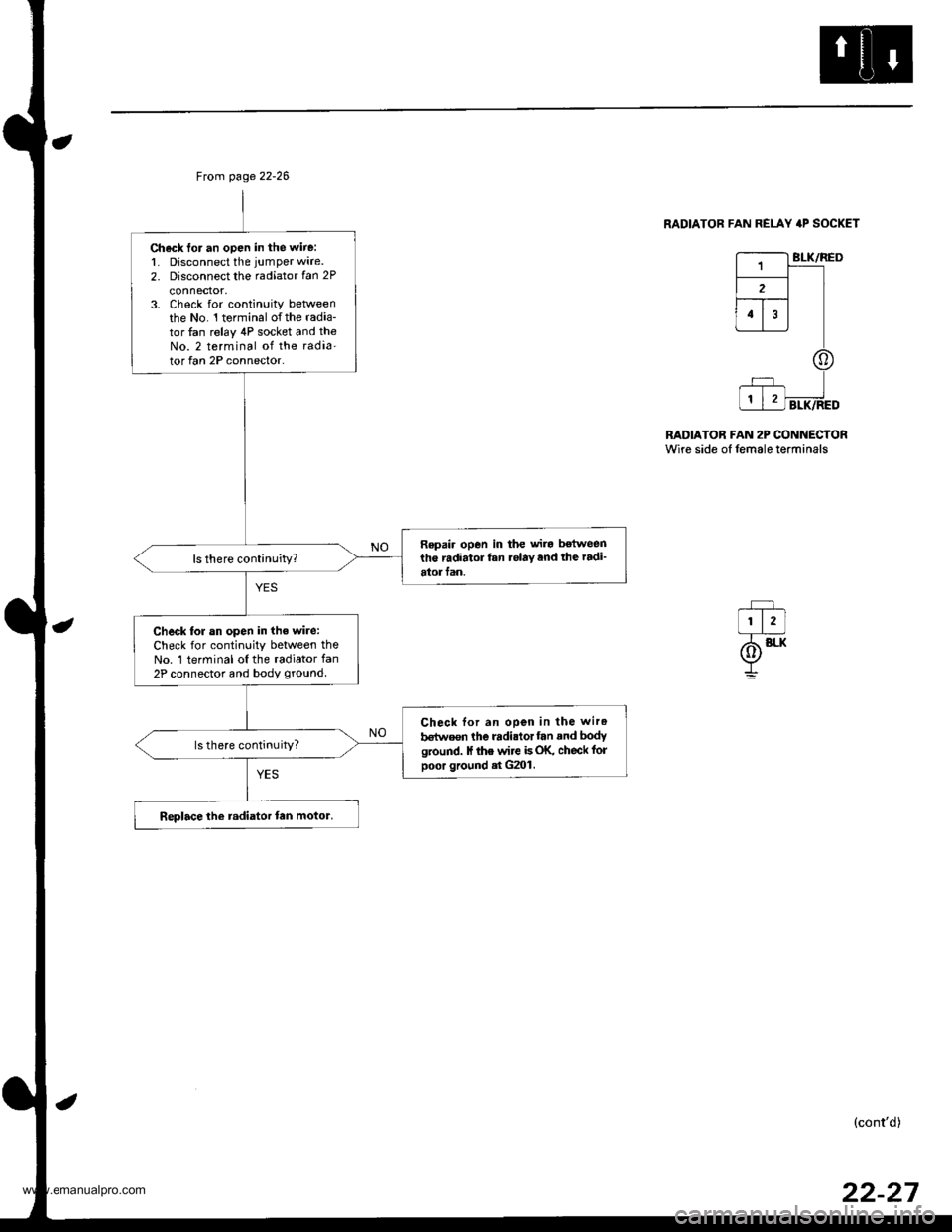
Ch6ck for an open in the wire:1. Disconnect the jumper wire.
2. Disconnect the radiator fan 2P
3. Check for continuity beNveenthe No. l terminal o{the radia-tor fan relay 4P socket and theNo. 2 terminal of the radia'tor fan 2P connector-
Repai. open in the wira betweenthe radiator fan .olay ,nd the radi'atorfan.
Check lor an open in the wi.e:Check for continuity between theNo. 1 terminal oI the radiator fan2P connector and body ground.
Check lor an open in the wir.
b€turosn the radi.tor fan and bodyground. lf ihe wire b OK, check folpoor ground .t G2()l .
ls there continuity?
Replace the radiator tan motor.
Ftom page 22-26
RADIATOR FAN REI-AY 4P SOCKET
BLK/RED
RADIATOR FAN 2P CONNECTORWire side of lemale terminals
(cont'd)
www.emanualpro.com
Page 1118 of 1395

Troubleshooting
Radiator Fan (cont'dl
From page 22-26
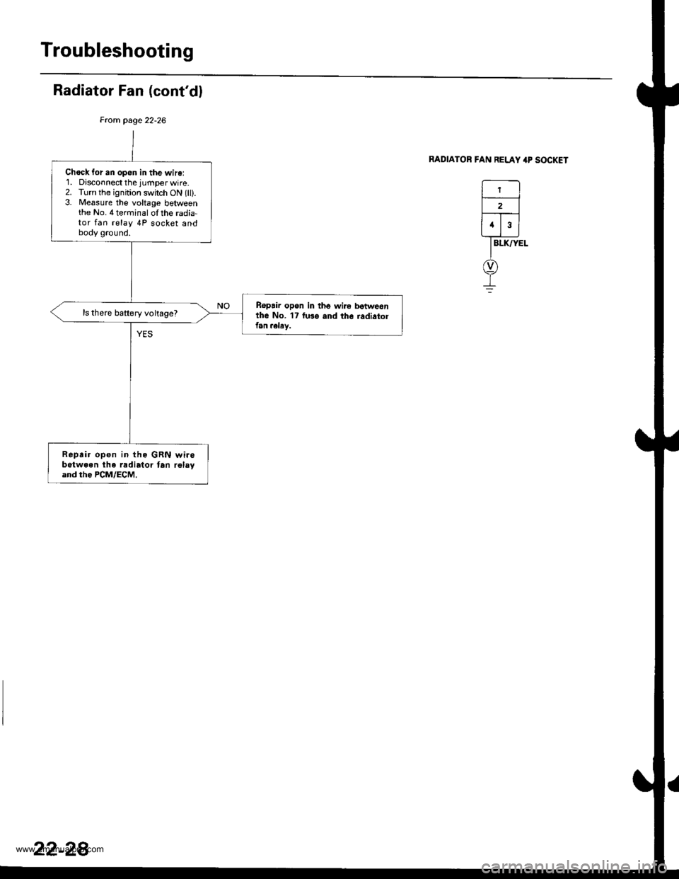
RADIATOR FAN RELAY 4P SOCKET
BLK/YEL
1
2
a
Chock for an open in the wire:'1. Disconnect the jurnper wire.2. Turn the ignition switch ON (ll).3. lleasure the voltage betweenthe No.4terrninal of the radia-tor fan relay 4P socket andbody ground.
R€pair open in th6 wire botwoonthe No. 17 fuso and the radiatolfan .elsy.
ls there battery voltage?
Rep.ir open in the GRN wirebotw€en lhe radiator tan relayand the PCM/ECM.
22-28
www.emanualpro.com