3rd clutch pressure switch HONDA CR-V 1999 RD1-RD3 / 1.G Workshop Manual
[x] Cancel search | Manufacturer: HONDA, Model Year: 1999, Model line: CR-V, Model: HONDA CR-V 1999 RD1-RD3 / 1.GPages: 1395, PDF Size: 35.62 MB
Page 270 of 1395
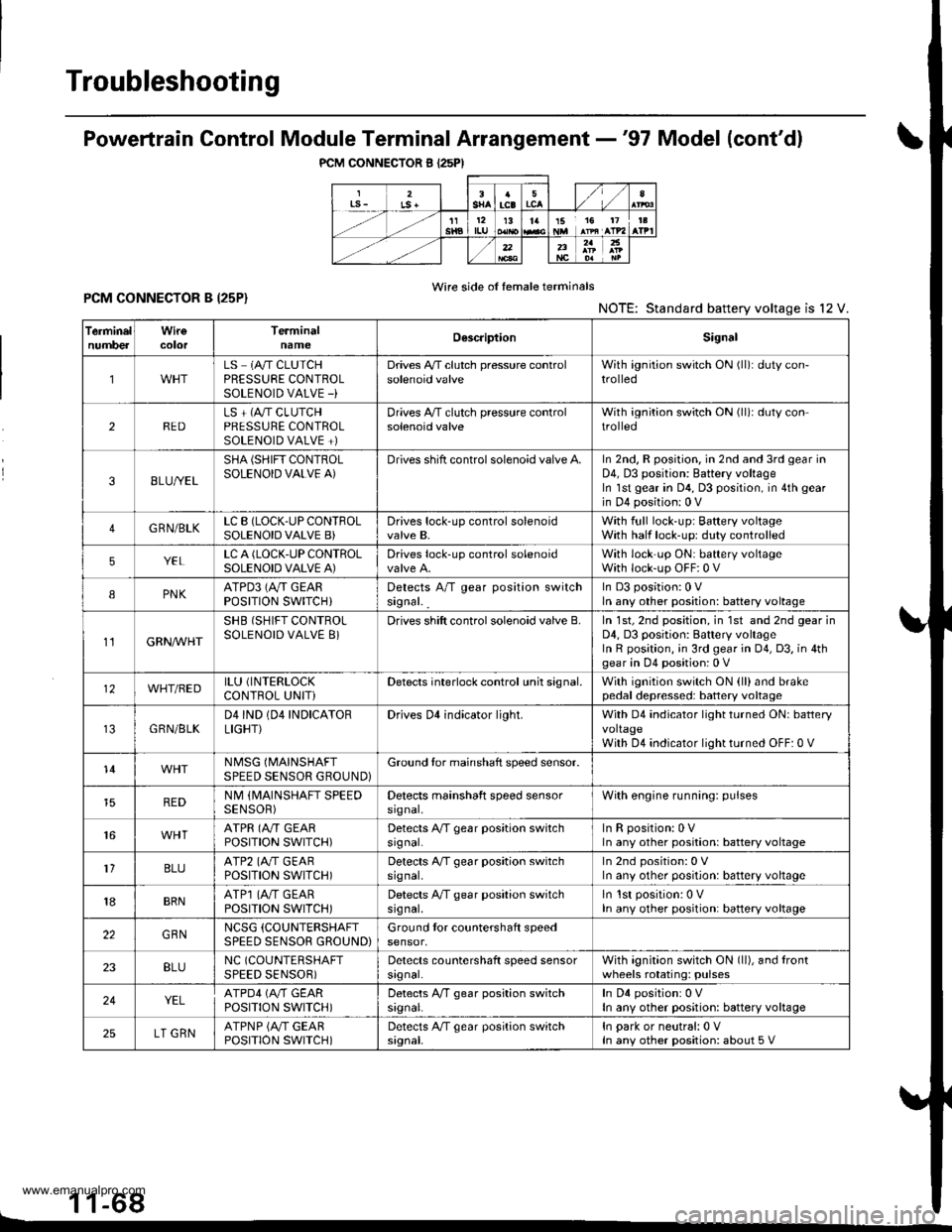
Troubleshooting
PCM CONNECTOR B I25PI
Powertrain Control Module Terminal Arrangement -'97 Model (cont'dl
Wire side of female terminalsPCM CONNECTOR B I25P}NOTE: Standard battery voltage is l2 V.
1 1-68L
TerminelnumbercolorTerminalnameOescriptionSignal
1LS 1A/T CLUTCHPRESSURE CONTROLSOLENOID VALVE -)
Drives A,/T clutch pressure controlsolenoid valveWith ignition switch ON (ll): duty con-trolled
2REDLS + (A"/T CLUTCHPRESSURE CONTROLSOLENOID VALVE +)
Drives A,/T clutch pressure controlsolenoid valveWith ignition switch ON (ll)r duty controlled
38LU//EL
SHA (SHIFT CONTROLSOLENOID VALVE A)Drives shift control solenoid valve A.In 2nd, R position. in 2nd and 3rd gear inD4, D3 position: Battery voltageIn lst gear in D4, D3 position, in 4th gear
in D4 position: 0 V
4GRN/BLKLC B (LOCK-UP CONTFOLSOLENOID VALVE B)Drives lock-up control solenoidvalve B,With full lock-up; Baftery voltageWith half lock-up: duty controlled
5YELLC A (LOCK.UP CONTROLSOLENOID VALVE A)Drives lock-up control solenoidWith lock'up ON: battery voltageWith lock-up OFF:0 V
IPNKATPD3 (Ay'T GEARPOSITION SWITCH}Detects A/T gear position switchsignal. _
In D3 position:0 Vln any other position: battery voltage
11GRN/VVHT
SHB (SHIFT CONTROLSOLENOID VALVE 8}Drives shift control solenoid valve B.In 1st, 2nd position, in 1st and 2nd gear inD4, D3 position: Battery voltageIn R position, ;n 3rd gear in 04, D3, in 4thgear in D4 position: 0 V
12WHT/BEDILU (INTERLOCK
CONTROL UNITiDetects interlock control unh signal.With ignition switch ON (ll)and brakepedal depressed: battery voltage
GRN/BLKD4IND (04 INDICATORLIGHT}Drives Dl indicator light.With D4 indicator light turned ON: batteryvoltageWith D4 indicator light turned OFF: 0 V
14NMSG (MAINSHAFT
SPEED SENSOR GROUND}Ground tor mainshaft speed sensor.
REDNM (MAINSHAFT SPEEDSENSOR)Detects mainshaft speed sensorsrgnal,With engine running: pulses
16ATPR (A"/T GEARPOSITION SWITCH)Detects A/T gear position switchsrgnal.InRposition:0VIn any other position: battery voltage
1'lBLUATP2 (A./T GEARPOSITION SWITCH)Detects A/T gear position switchsrg nal,In 2nd position: 0 VIn any other position: battery voltage
18BRNATP1 (4,,/T GEARPOSTTTON SWTTCH)Detects A/T gear position switchsrg nal,ln lst position: 0 VIn any other position: battery voltage
22GBNNCSG (COUNTERSHAFT
SPEED SENSOR GROUND)Ground tor countershaft speedsensor,
23BLUNC (COUNTERSHAFT
SPEED SENSOR)Detects countershaft speed sensorsrgnal.With agnition switch ON (ll), and lrontwheels rotating: pulses
24YELATPD4 (M GEARPOSITION SWITCH)Detects A,/T gear position switchsrgnal.In D4 positionr 0 VIn any other position: battery voltage
25LT GRNATPNP {A/T GEARPOSITION SWITCH)Detects A/T gear position switchsignal.In park or neutral:0 VIn any other position: about 5 V
www.emanualpro.com
Page 519 of 1395

Description
General Operation
The Automatic transmission is a 3-element torque converter and triple-shaft electronically controlled unit which provides 4
speeds forward and 1 reverse speed The unit is positioned in line with the engine'
There are two tvoes of automatic transmission on CR-V; the four-wheel drive (4WD) model ('97 - 00)' and the front-wheel
drive (2WD) model ('98 - 00).
Toroue Converter, G€ars, and Clutches
The torque converter consists of a pump. turbine. and stator assembly in a single unit. The torque converter is connected to
the engine crankshatt. These parts turn together as a unit as the engine turns. Around the outside of the torque converter is
a ring gear which meshes with the starter pinion when the engine is started. The torque converter assembly serves as a fly-
wheel while transmitting power to the transmission mainshaft.
The transmission has three parallel shafts: the mainshaft. the countershaft, and the sub-shaft. The mainshaft is in line with
the engine crankshaft. The mainshaft includes the 1st, 2nd. and 4th clutches, and gears lor 3rd,2nd,4th. reverse and 1st
(3rd gear is integral with the mainshaft, while reverse gear is integral with the 4th gear). The countershaft includes the 3rd
clutch and gears for 3rd,2nd, 4th, reverse, 1st, and park. Reverse and 4th gears can be locked to the countershaft at its cen-
ter, providing 4th gear or reverse, depending on which way the selector is moved. The sub-shaft includes the lst-hold
clutch and gears for lst and 4th.
The gears on the mainshaft are in constant mesh with those on the countershaft and sub-shaft. When certain combinations
of gears are engaged by the ctutches, power is transmitted from the mainshaft to the countershaft to provide E, D!, tr, tr,
and E position ('97 - 98 models). and E. E, E, and E position ('99 - 00 models)'
Electlonic Control
The electronic controt system consists of the Powenrain Control Module (PCM), sensors, a linear solenoid, and four
solenoid valves. Shifting and lock-up are electronically controlled for comfortable driving under all conditions. The PCM is
located below the dashboard, under the kick panel on the passenger's side.
Hydraulic Control
The valve bodies include the main valve body, the secondary valve body, the regulator valve body, the servo body, and
the lock up valve body. They are bolted to the torque converter housing. The main valve body contains the manual valve,
the 1-2 shift valve, the 2nd orifice control valve. the CPB {Clutch Pressure Back-up) valve, the modulator valve, the servo
control valve. the relief valve, and ATF pump gears. The secondary valve body contains the 2-3 shift valve, the 3-4 shift
valve, the 3,4 orifice control valve. the 4th exhaust valve and the CPC (Clutch Pressure Control) valve. The regulator valve
bodv contains the pressure regulator valve, the torque converter check valve, the cooler relief valve, and the lock-up con-
trol valve. The servo body contains the servo valve which is integrated with the reverse shift tork, and the accumulators
The lock-up valve body contains the lock-up shift valve and the lock-up timing valve. The linear solenoid and the shift con-
trol solenoid valve Ay'B are bolted to the outside of the transmission housing, and the lock-up control solenoid valve Ay'B is
bolted to the outside of the torque converter housing. Fluid trom the regulator passes through the manual valve to the
various control valves. The clutches receive fluid from their respective feed pipes or internal hydraulic circuit
ShiftControl Mechanism
input from various sensors located throughout the vehicle determines which shift control solenoid valve the PCM will acti-
vate. Activating a shift control solenoid valve changes modulator pressure, causing a shift valve to move. This pressurizes
a line to one of the clutches. engaging that clutch and its corresponding gear. The shift control solenoid valves A and B are
controlled by the PCM.
Lock-up Mechanism
tn E! position (,97 - 98 modets) and in E position ('99 - O0 models), in 3rd and 4th, and in Del position in 3rd ('97 - 98
models) and in El position with Over,Drive (O/D) is OFF (by pressing rhe O/D switchl in 3rd ('99 - 00 models), pressurized
fluid is drained from the back of the torque converter through a fluid passage, causing the lock-up piston to be held
against the torque converter cover, As this takes place, the mainshaft rotates at the same speed as the engine crankshaft.
Together with hydraulic control, the PcM optimizes the timing of the lock-up mechanism The lock-up valves control the
range of lock-up according to lock-up control solenoid valves A and B, and the linear solenoid. When lock-up control
solenoid valves A and B activate, the modulator pressure changes. The lock-up control solenoid valves A and B and the
linear solenoid are controlled by the PCM.
{cont'd)
14-3
www.emanualpro.com
Page 520 of 1395
Description
General Operation (cont'dl
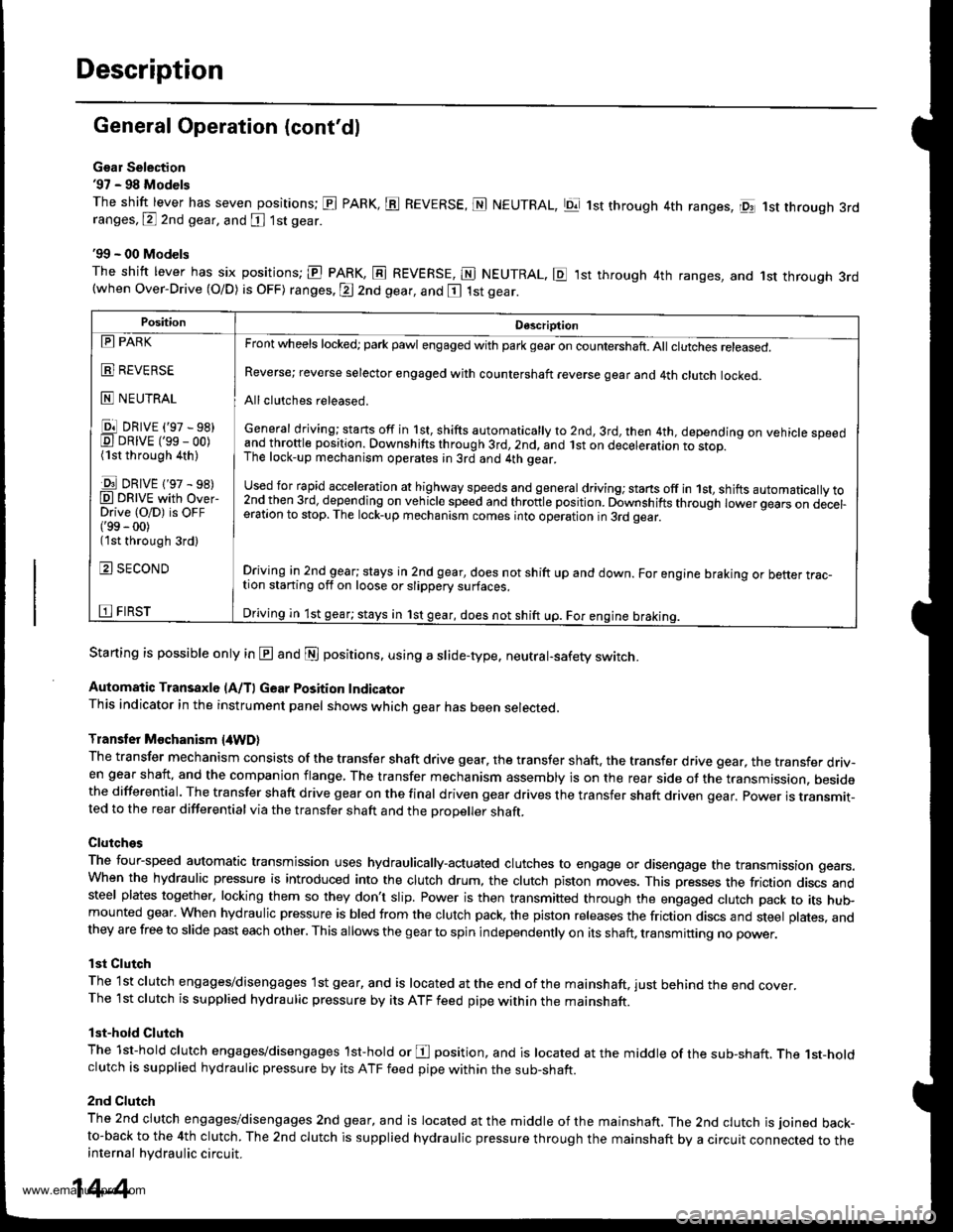
Gsar Selection'97 - 98 Models
The shift lever has seven positions; El PARK, ts REVERSE, N NEUTRAL, Ell 1st through 4th ranges, lpq 1st th.ough 3rdranges, P 2nd gear, and [ 1st gear
'99 - 00 Models
The shitt lever has six positions; El PARK, E REVERSE, E NEUTRAL. E ,lst through 4th ranges, and 1st through 3rd(when Over-Drive (O/D) is OFF) ranges. @ 2nd gear, and E 1st gear.
Starting is possible only in @ and @ positions. using a slide-type. neutral-safety switch.
Automatic Transaxle (A/T) Gear Position IndicatorThis indicator in the instrument panel shows which gear has been selected.
Transler Mochanism {4WD}
The transfer mechanism consists of the transfer shaft drive gear. the transfer shaft. the transfer drive gear, the transfer driv-en gear shaft, and the companion flange, The transfer mechanism assembly is on the rear side ot the transmission. besidethe differential. The transfer shaft drive gear on the final driven gear drives the transfer shaft driven qear. power is transmit-ted to the rear differential via the transfer shaft and the Drooeller shaft.
Clutches
The four-speed automatic transmission uses hydraulically-actuated clutches to engage or disengage the transmission gears.When the hydraulic pressure is introduced into the clutch drum, the clutch piston moves. This presses the friction discs andsteel plates together, locking them so they don't slip. Power is then transmifted through the engaged clutch pack to its hu$mounted gear. When hydraulic pressure is bled from the clutch pack, the piston releases the friction discs and steel plates, andthey are free to slide past each other. This allows the gearto spin independently on its shaft, transmitting no power.
lst Clutch
The 1st clutch engages/disengages lst gear, and is located at the end ofthe mainshaft, just behind the end cover.The 1st clutch is supplied hydraulic pressure by its ATF feed pipe within the mainshaft.
lst-hold Clutch
The 1st-hold clutch engages/disengages 1st-hold or E position, and is located at the middle of the sub-shaft. The 1st-holdclutch is supplied hydraulic pressure by its ATF feed pipe within the sub-shaft.
2nd Clutch
The znd ciutch engages/disengages 2nd gear, and is located at the middle of the mainshaft. The 2nd clutch is joined back-to-back to the 4th clutch. The 2nd clutch is supplied hydraulic pressure through the mainshaft by a circuit connected to theinternal hydraulic circuit.
PositionDescription
Reverse; reverse selector engaged with countershaft reverse gear and 4th clutch locked.
Allclutches released.
General driving; starts off in 1st, shifts automatically to 2nd, 3rd, then 4th, depending on vehicle speedand throftle position. Downshifts through 3rd,2nd, and lst on deceleration to stop.The lock-up mechanism operates;n 3rd and 4th gear.
used for rapid €cceleration at highway speeds and general driving; stans off in 1st, shifts automatically to2nd_then 3rd, dejending on vehicle speed and throttle position. Downshifts through lower gears on decel-eration to stop. The lock-up mechanism comes into operation in 3rd gear.
Driving in 2nd_gear; stays in 2nd gear, does not shift up and down. For engine braking or better trac_tion starting off on loose or slippery surfaces.
Driving in 1st gear; stays in 1st gear, does not shift up. For engine braking.
tll PARK
t!!l l|EvEn>E
E NEUTRAL
Ell DRrvE ('97 - sB)E DRrvE ('ss - oo)(1st through 4th )
E DRrvE {'97 - s8)O DRTVE with over-Drive (O/D) is OFF('99 - 00)(1st through 3rd)
E SECOND
E FIRST
14-4
www.emanualpro.com
Page 555 of 1395
Lock-up System
TOROUE CONVERTER
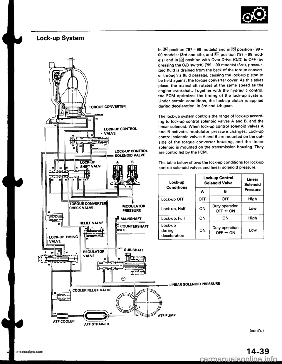
In E position ('97 - 98 models) and in E position ('99 -
OO models) (3rd and 4th), and E position ('97 - 98 mod-
els) and in E position with Over-Drive (O/D) is OFF (by
pressing the O/D switch) ('99 - 00 models) (3rd), pressur-
ized fluid is drained from the back of the torque convert-
er through a fluid passage, causing the lock-up piston to
be held against the torque converter cover, As this takes
Dlace, the mainshaft rotates at the same speed as th8
engine crankshaft. Together with the hydraulic control,
the PCM optimizes the timing of the lock-up system.
Under certain condltions. the lock-up clutch is appli€d
during deceleration, in 3rd and 4th gear.
The lock-up system controls the range of lock-up sccord-
ing to lock-up control solenoid valves A and B, and ths
linear solenoid. When lock-up control solenoid valves A
and B activate. modulator pressure changes. Lock-up
control solenoid valves A and B are mounted on the out-
side of the torque converter housing, and the linear
solenoid is mounted on the transmission housing. They
are controlled bv the PCM.
The table below shows the lock-up conditions for lock-up
control solenoid valves and linear solenoid pressure.
LINEAR SOLENOID PRESSURE
(cont'd)
LOCK.UP CONTROL' VALVE
LOCK.UP CONTROLSOLENOID VALVE
AB
MODULATORPf,ESSURE
MAINSHAFT
COUNTERSHAFT
SUB.SHAFT
Lock-up
Conditions
Lock-up Conirol
Solenoid valveLinaal
Solenoid
PrgssulsAB
Lock-up OFFOFFOFFHigh
Lock-up, HalfONDuty operation
OFF - ONLow
Lock-up, FullONONHigh
Lock-up
during
deceleration
ONDuty operation
OFF - ON
RELIEF VALVE
LOCK'UP TIMINGVALVE
COOLER RELIEF VALVE
ATF COOLERATF STRAINER
ATF PUMP
14-39
www.emanualpro.com
Page 670 of 1395
Symptom-to-Component Chart
Hydraulic System (cont'd)
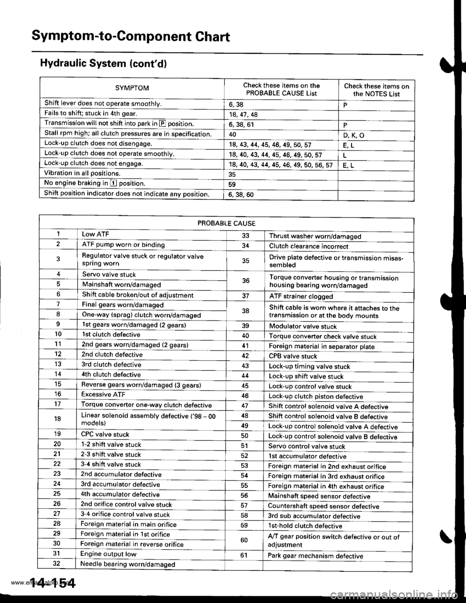
SYMPTOMCheck these items on thePROBABLE CAUSE ListCheck these items onthe NOTES Lisr
Shift lever does not operate smoothly.o, JdPFails to shift; stuck in 4th gear.14, 41 , 48
Transmission will not shift into park in E position.6, 38, 61PStall rpm high; all clutch pressures are in specification.40D,K,OLock-up clutch does not disengage.18, 43, 44, 45, 46, 49,50,57
Lock-up clutch does not operate smoothly.14, 40, 43, 44, 45, 46, 49, 50. 57Lock-up clutch does not engage.'t8, 40, 43, 44, 45, 46, 49, 50, 56, 57Vibration in all positions.
No engine braking in I position.59
Shift position indicator does not indicate anv position,6. 38, 60
PROBABLE CAUSE
I 33 Thrust washer worn/damaged
ATF pump worn or binding34Clutch clearance incorrect
Regulator valve stuck or regulator valvespflng wornDrive plate delective or transmission mtsas-sembled
Servo valve stuck5ttTorque converter housing or transmissionhousing bearing worn/damagedMainshaft worn/damaged
Shift cable broken/out of adjustmentATF strainer clogged
7Final gears worn/damaged38Shift cable is worn where it attaches to thetransmission or at the body mountsIOne-way (sprag) clutch worn/damaged
1st gears worn/damaged {2 gears)39Modulator valve stuck10lst clutch defective40Torque converter check valve stuck112nd gears worn/damaged (2 gears)41Foreign material in separator plate't22nd clutch defectiveCPB valve stuck
t53rd clutch defective43Lock-up timing valve stuck144th clutch defective44Lock-up shift valve stucktcReverse gears worn/damaged (3 gears)Lock-up control valve stuck16Excessive ATF46Lock-up clutch Diston defective17Torque converter one-way clutch defective47Shift control solenoid valve A defecttve
18Linear solenoid assemblv defective (,98 - OOmodels)48Shift control solenoid valve B dsfectrve
49Lock-up control solenoid valve A defective'19CPC valve stuckLock-up control solenoid valve B deleqtve20l-2 shift valve stuck51Servo control valve stuck212-3 shift valve stuck52lst accumulator defective3-4 shift valve stuck53Foreign material in 2nd exhaust orifice2nd accumulator defective54Foreign material in 3rd exhaust orifice3rd accumulator defectiveForeign material in 4th exhaust orifice4th accumulator defective56Mainshaft speed sensor defective262nd orifice control valve stuckCountershaft speed sensor defective273-4 orifice control valve stuck583rd sub accumulator defective2aForeign material in main orifice59lst-hold clutch defective29Foreign material in lst orifice60A/T gear position switch defective or out ofadjustment30Foreign material in reverse orifice
31Engine output low61Park gear mechanism defective32Needle bearing worn/damaged
14-154
www.emanualpro.com
Page 679 of 1395
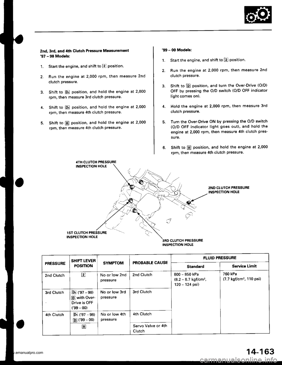
znd, 3rd, and ,lth Clutch Pressurs Measuremenl'97 - 98 Modols:
1. Stan the engine, and shift to E position.
2. Run the engine at 2,000 rpm, then measure 2nd
clutch pressure.
3. Shift to E position, and hold the engine at 2'000
rpm, then measure 3rd clutch pressure.
4. Shift to E position, and hold the engine at 2,000
rpm, then measure 4th clutch pressure.
5. Shift to @ position, and hold the engine at 2,000
rpm, then measure 4th clutch pressure.
4TH CLUTCH PRESSUREINSPECTION HOLE
'99 - 00 Models:
1. Start the engine, and shift to El position.
2. Run the engine at 2,000 rpm. then measure 2nd
clutch pressure.
3. Shift to E position, and turn the Over-Drive (O/D)
OFF by pressing the O/D switch (O/O OFF indicator
light comes on).
4. Hold the engine at 2,000 rpm, then measure 3rd
clutch Pressure.
5. Turn the Over-Drive ON by pressing the O/D switch
(O/D OFF indicator light goes out), and hold the
engine at 2,000 rpm, then measure 4th clutch pres-
sure.
6. Shift to E position, and hold the engine at 2,000
rpm, then measure 4th clutch prgssure
2ND CLUTCH PRESSUREINSPECTION HOLE
3RD CLUTCH PRESSUREINSPECTION HOLE
'"r.,-ur"" "..#
- -t"1' -.
INSPECTION HOLE
PRESSURESHIFT LEVER
POSmONSYMPTOMPROBABLE CAUSE
FLUID PRESSURE
StandardServico Limit
2nd ClutchtrNo or low 2nd
pres$ure
2nd Clutch800 - 850 kPa
\A.2 - 8.1 kgtlcm2,'120 - '124 psil
760 kPa
(7.7 kgf/cm'�, 110 psi)
3rd ClutchE (97 - s8)
Elwith Over-
Drive is OFF(99 - 00)
No or low 3rd
pressure
3rd clutch
4th clutchE (97 ,98)
E (99 - oo)
No or low 4th
pressure
4th Clutch
EServo Valve or 4th
Clutch
14-163
www.emanualpro.com