Condenser HONDA CR-V 1999 RD1-RD3 / 1.G Workshop Manual
[x] Cancel search | Manufacturer: HONDA, Model Year: 1999, Model line: CR-V, Model: HONDA CR-V 1999 RD1-RD3 / 1.GPages: 1395, PDF Size: 35.62 MB
Page 36 of 1395
to
l
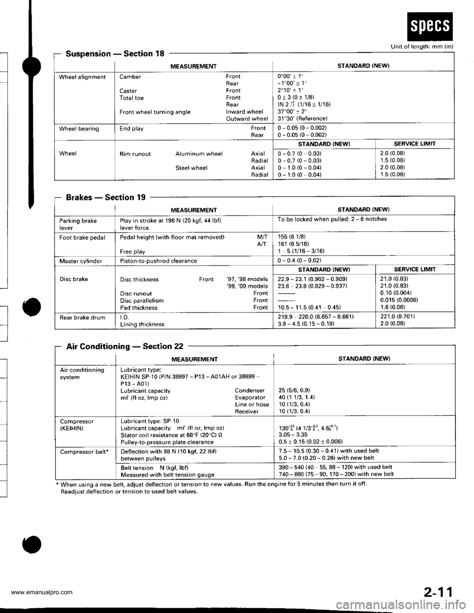
SuspensionSection 18
BrakesSec'tion 19
Air ConditioningSection 22
* When using a new belt, adjust deflection or tension to new values. Run the engine for 5 minutes then turn it off.
Readjust deflection or tension to used belt values.
o
Unit of length: mm {in)
MEASUREMENTSTANDARD {NEW)
WheelalignmentCamber FrontRearCaster FrontTotaltoe FrontnearFront wheel turning angle Inward wheelOutward wheel
0"00' 1 1'- 1"00' 1 1'2"10' ! 1"0J3(011/8)rN 2 ri (1/161 1/r6)37"00' ! 231'30'(Referencei
Wheel bearingEnd playFrontRear0 - 0.05 {0- 0.002}0 - 0.05 (0 0.002i
Rim runout Aluminum wheel AxialBadialSteelwheel AxialRadial
STANOARD (NEW)SERVICE LIMIT
0 - 0.7 (0 0.03)0,0.7 (0 - 0.03)0 1.0 (0 - 0.04)0 - 1.0 {0 - 0.04)
2.0 (0.08)'r.5 {0.06)2.0 {0.08)1.s (0.06)
MEASUREMENTSTANDARD INEWI
Parking brakeleverPlay in stroke at 196 N (20 kgf,44lbf)lever force
To be locked when Dulled: 2 - 6 notches
Foot brake pedalPedal height (with tloor mat removed)
Free playNT
155 (6 1/8)161 (6 5/16)1 5 (1/16 - 3/16)
Master cylinderPiston-to-pushrod clearance0 - 0.4 (0- 0.02)
Disc brakeDisc thickness Front '97, '98 models'99, '00 modelsDisc runoutDisc parallelismPad thickness
FrontFrontFront
STANDARD {NEW'SERVICE LIMIT
22.9 - 23.1 (0.902 - 0.909)23.6 23.8 (0.929 - 0.937)
10.5 - 11.5 (0.4'�t 0.45)
21.0 (0.83)
21.0 (0.83)
0.10 {0.004)0.015 (0.0006)
1.6 (0.06)
Rear brake drumLD.Lining thickness
2r9.9 220.0 (8.657 - 8.661)3.9 - 4.5 (0.15 - 0.18)221.O 8.70112.0 (0.08)
MEASUREMENTSTANDARD {NEWI
Air conditioningLubricant type:KEIHIN SP 10 (P/N 38897 - Pl3 - A01AH or 38899 -
Pl3 - A01)Lubricant capacity Condensermf {floz, lmp oz) EvaporatorLine or hoseReceiver
25 (5/6,0.9)
40 {1 1/3, 1.4)10 {1/3,0.4)10(.]/3,0.4)
Compressor(KEIHIN)Lubricant type: SP 10Lubricant capacity ml ({l 02, lmp oz}Stator coil resistance at 68'F (20"C) OPulley-to-pressuae plate clearance
130'3'{4 1fi'3o, 4.6;"}3.05 - 3.350.51 0.15 (0.02 1 0.006)
Compressor belt*Deflection with 98 N (10 kgl,22lblibetween pulleys7.5 - 10.5 {0.30 - 0.41) with used belt5.0 - 7.0 (0.20 - 0.28) with new belt
Belt tension N (kgf, lbf)Measured with belt tension gauge390 - 540 (40 55,88-120)withusedbelt740 - 880 {75 90, 170 - 200) with new belt
2-11
www.emanualpro.com
Page 38 of 1395

--
-
METRICITEMENGLISHNOTES
AIR CONDITIONINGCooling capacity3,520 Kcal/h j 14,000 BTU/h
Compressor Type/manutacturerNo. of cylinderCaPacityMax. speedLubricant capacityLubricant type
Scroll/KElHlN
85.7 mf/rev | 5.23 cu'in/rev10,000 rpm130mf 1 algIlozsP-10
Condenser TypeCorrugated fin
Evaporator TypeCorrugated fin
Blower TypeMotor inputSpeed controlMax. capacity
Sirocco fan200 w 112 v4-Speeo440 m3/h 15,500 cu fvh
Temperature control
Compressor clutch TypePower consumptionDry, single plate, poly-V-belt drive40 W max./12 VAt 68'F (20 C)
Befrigerant TypeOuantity
HFC-134a 1R-134a)zoo o' g 24j an oz
STEERING SYSTEMTypeOverall ratioTurns, lock to lockSteering wheel diameter
Power assisted, rack and pinion
SUSPENSIONType Front
Bear
Shock absorber Front and Rear
Independent double wishbone, coil springwith stabilizerIndependent double wishbone, coil springwith stabilizerTelescopic, hydraulic nitrogen gas tilled
WHEEL ALIGNMENTCamber
CasterTotaltoe
FronthearFrontFrontRear0inln 1/16 in0mmln2mm
0'- r"00'2.10'�
BRAKE SYSTEMTvpe
Pad surface areaLining surface areaParking brake
Front
RearFrontRearTvpe
Power-assisted selt-ad,ustingventilated discPower assisted self-adiusting drum49 cm, x 2 7.6 sq-in x 273 cm, x2 11.3 sq-in x 2Mechanical actuating, rear two wheel brakes
Drum brake
TIRESize and pressureSee tire inlormation label.
ELECTRICALBafteryStarterAlternator
In under-dash fuse/relay boxIn under hood fuse/relay box
In underhood ABS fuse/relay boxHeadlightsFront turn signal lights
Front parking lightsFront side marker lightsRear side marker lightsRear turn signal lightsErake/parking lightsBack-up lightsCeiling lights {fronvrear)License plate lightSpotlightsHigh mount brake lightlgnition key lightAshtray lightGauge lightsIndicator lightslllLrmination and pilot IightsHeater illumination lights
12 V, 36 AH/s HR12V 1.0, 1.1 kW12V 100A
7.5 A, 10 A, 15 A, 20 A7.5 A, 10 A, 15 A, 20 A, 30 A, 40 A'100 A7.5 4,20 A. 40 A12V 60/55 W12 V- 21 W ('97 model),12 V - 27 W ('98-00 models)12V 5 W {'97 model),3 CP ('98 - 00 models)12V-8W12 V,3 CP12V-21W12 V 2115 W12V 21 CP (18 W)12V-8W12V-8W12V-5W12V -21W
12 V- 1.4 W12V 1.4 W12 V 1.4 W,3 W,3.4 W12V-0.84W, 1.12 W, 1.4 W,3 W, LED12 V - 0.84 W, 1.4 W, LED12 V,1.4 W
2-13
www.emanualpro.com
Page 192 of 1395
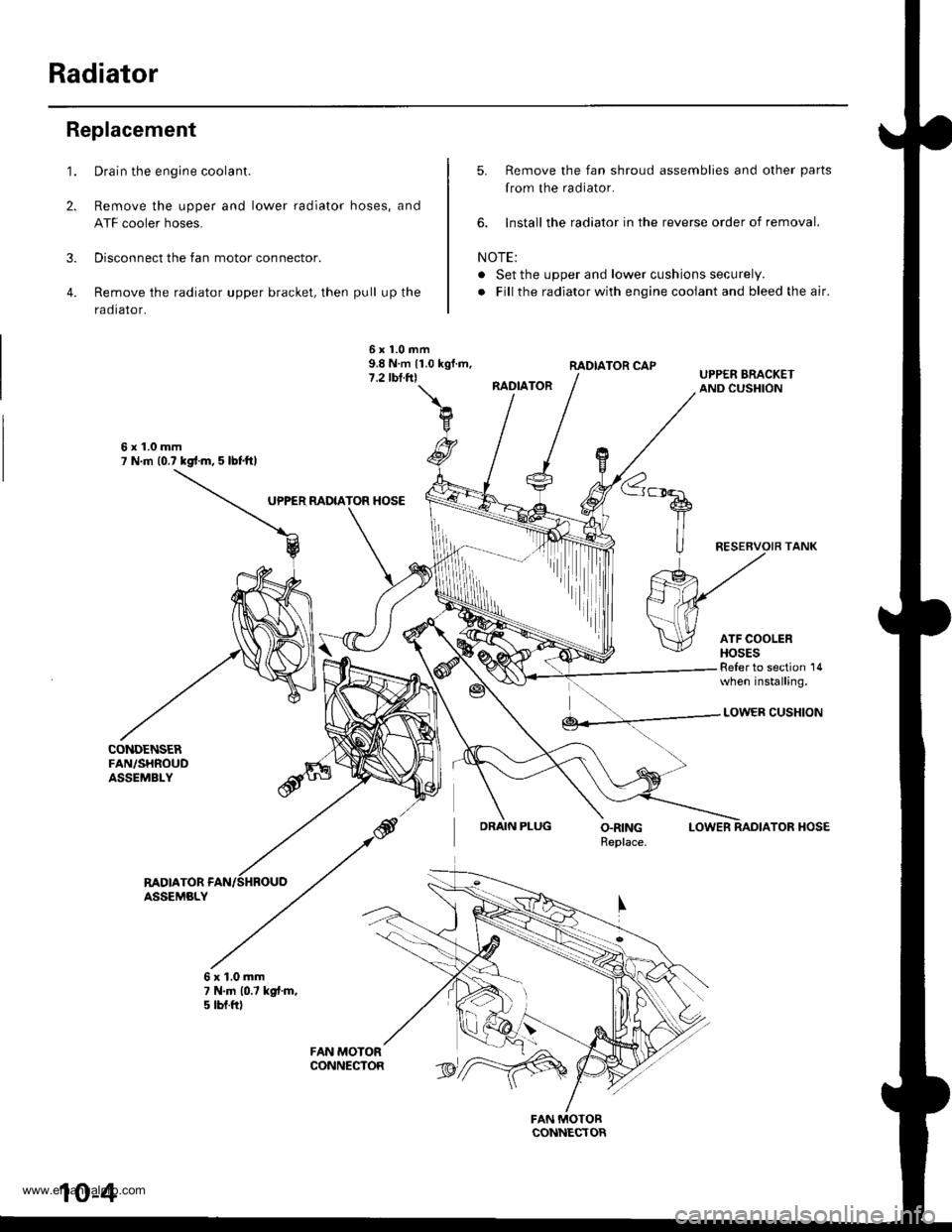
Radiator
1.
2.
3.
4.
Replacement
CONDENSERFAN,/SHROUDASSEMBLY
Drain the engine coolant.
Remove the upper and lower radiator hoses, and
ATF cooler hoses.
Disconnect the fan motor connector.
Remove the radiator upper bracket, then pull up the
raotalor,
5. Remove the fan shroud assemblies and other parts
from the radiator.
6. lnstall the radiator in the reverse order of removal.
NOTE:
. Set the upper and lower cushions securely.
. Fill the radiator with engine cooiant and bleed the air.
RADIATOR CAP
RADIATOR
6x1.0mm9.8 N.m 11.0 kgf.m,7.2 tbl.trl
6x1.0mm7 N.m (0.? kgd.m, 5 lbl.ftl
UPPER MDIATOR HOSE
Reler to section 14when installing.
DRAIN PLUG
LOWER CUSHION
LOWERTOR HOSE
RADIATORASSEMBLY
6x1.0mm7 N.|n 10.7 kgt.m,5 tbt.ftl
rriItriiii
10-4
www.emanualpro.com
Page 200 of 1395
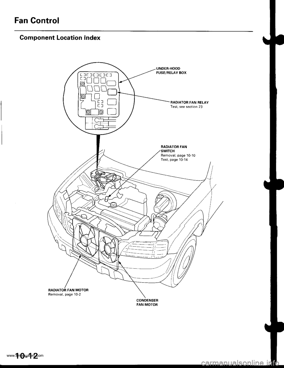
Fan Control
Component Location Index
UNDEB.HOODFUSE/RELAY BOX
RADIATOR FAN RELAYTest, see section 23
BADIATOR FAN
Removal, page 10-10Test, page 10-14
BADIATOR FAN MOTORRemoval, page 10-2
CONDENSERFAN MOTOR
ftflEffltrlt lrt r-1 a-l
@u!lfl]l
10-12
www.emanualpro.com
Page 222 of 1395
BLK,TEL JflIBLU rdHT - Frrt
FEl, | | L-fJlalx -----L+ |
l-
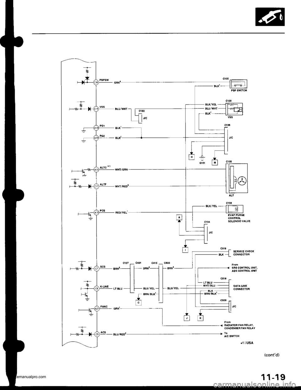
CONDENSERFAN FELAY
*1 : USA
(cont'd)
1 1-19
www.emanualpro.com
Page 282 of 1395

PGM-FI System
System Description
INPUTS
CKP/TDC/CYP Sensor
CKF Sensor
MAP Sensor
ECT Sensor
IAT Sensor
TP Sensor
Primary HO2S
Secondary H02S
vss
KS*5
BARO Sensor
ELD*6
Starter Signal
ALT FR Signal
Air Conditioning Signal
Ay'T Gear Position Signal*1
Baftery Voltage (lGN.1)
Brake Switch Signal
PSP Switch Signal
Fuel Tank Pressuae Sensor*4. *5
Countershaft Speed Sensor*1
Mainshaft Speed Sensor*r
OVER-DRIVE Switch Signal*s
ENGINE CONTROL MODULE (ECM)/
POWERTRAIN CONTROL MODULE (PCM) OUTPUTS
|iuel 1"j""- Th,rhg ""d Drrafr";-l
Et*-.nt"tdt"cont.orl
to,r*,c;;trffi;]
l.----.---:. .Lrgnrnon |lmrng Lonrror I
Ecir/PcM B*k',p Fr""il]
m;"t-ll-r*'io*l
Fuel Injectors
PGM-Fl Main Relay (Fuel Pump)
MIL
IAC Valve
Ay'C Compressor Clutch Relay
Radiator Fan Relay
Condenser Fan Relay
ALT
tcM
EVAP Purge Control Solenoid
Valve
Primary HO2S Heater
Secondary H02S HeaterEVAP Bypass Solenoid Valve*a *5
EVAP Control Canister Vent Shut
DLC
Lock-up Control Solenoid Valve*l
Shift Control Solenoid Valve*1
Ay'T Clutch Pressure Control
Solenoid Valve*1
D4 Indicator Light'1 *3, *a
D Indicator Light,l *5
OVER-DRIVE OFF Indicator
Lighl*t *:
*1: A/T {3:'97 model'2: M/f +4:'98 model*5: '99 - 00 models"6: USA
PGM-Fl System
The PGM-Fl system on this model is a sequential multiport fuel injection system.
Fuel iniecior Timing and Duration
The ECM/PCM contains memories for the basic discharge durations at various engine speeds and manifold pressure. The
basic discharge duration, after being read out from the memory, is further modified by signals sent from various sensors
to obtain the final discharge duration.
ldle Air Control
ldle Air Control Valve (lAC Valve)
When the engine is cold, the Ay'C compressor is on, the transmission is in gear, the brake pedal is depressed, the P/S load
is high, or the alternator is charging, the ECM/PCM controls current to the IAC Valve to maintain the correct idle speed.
lgnition Timing Control
o The ECM/PCM contains memories for basic ionition timing at various engine speeds and manifold air flow rates.
lgnition timing is also adjusted for engine coolant temperature.
. A knock control system was adopted which sets the ideal ig nition timing for the octane rating of the gasoline used.*s
Other Control Funstions
1. Starting Control
When the engine is started. the ECM/PCM provides a rich mixture by increasing fuel injector duration.
2. Fuel Pump Control
. When the ignition switch is initially turned on (ll). the ECMiPCM suppli€s ground to the PGM-FI main relay that
supplies current to the fuel pump for two seconds to pressurize the fuel system.
. When the engine is running, the ECM/PCM supplies ground to the PGM-FI main relay that supplies current to the
fuel oumo.
. When the engine is not running and the ignition is on, the ECM/PCM cuts ground to the PGM-FI main relay which
cuts current to the fuel pump.
1 1-80
www.emanualpro.com
Page 1091 of 1395
Air Conditioning
Heater Control Panel
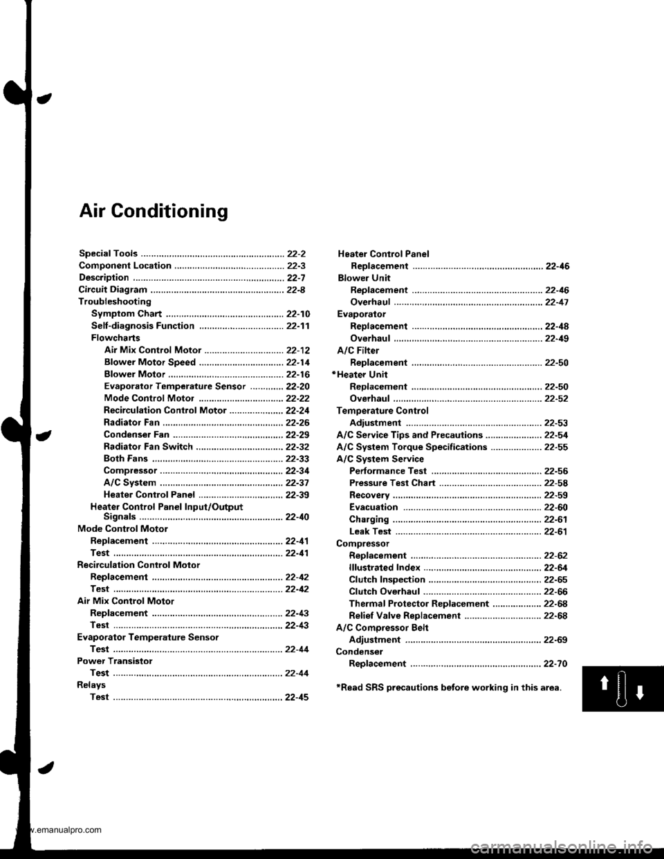
Reofacement ,.,...,,.,..,.,.,,22-46
Blower Unit
Replacement .................. 22-46
Overhaul ...........,,,., .......-.22-17
Evaporalor
ReDlacement ...,.,.,..,......,22-4A
Overhaul ................ .........22-19
A/C Filter
Replacement ..................22-50*Heater Unit
ReDfacement ..................22-50
Overhaul ..,.,..,.,...,.. .........22-52
Temperature Control
Adiustment ....................22-53
A/C Service Tips and Precauiions............-....-.... 22-54
A/C System Torque Specifications .................... 22-55
A/C System Service
Performance Test ......,...22-56
Pressure Test Chart .-.....22-5a
Recovery ..............,. ...-.-...22-59
Evacuation -...........-........22-60
Charging ................ .......-.22-61
Leak Test ........................22-61
Compressor
Repfacement ..........-.......22-62
flfustrated Index .....,.......22-64
Cfutch fnspection .........,.22-65
Cfutch Overhaul ............- 22-66
Thermaf Protector Rep|acement ................... 22-68
Refief Valve Replacement .............................. 22-68
A/C Comoressor Belt
Adiustment .................... 22-69
Condenser
Repfacement .,.....,,.,..,.,..22-70
'Read SRS precautions betore working in this area.
www.emanualpro.com
Page 1093 of 1395
Component Location
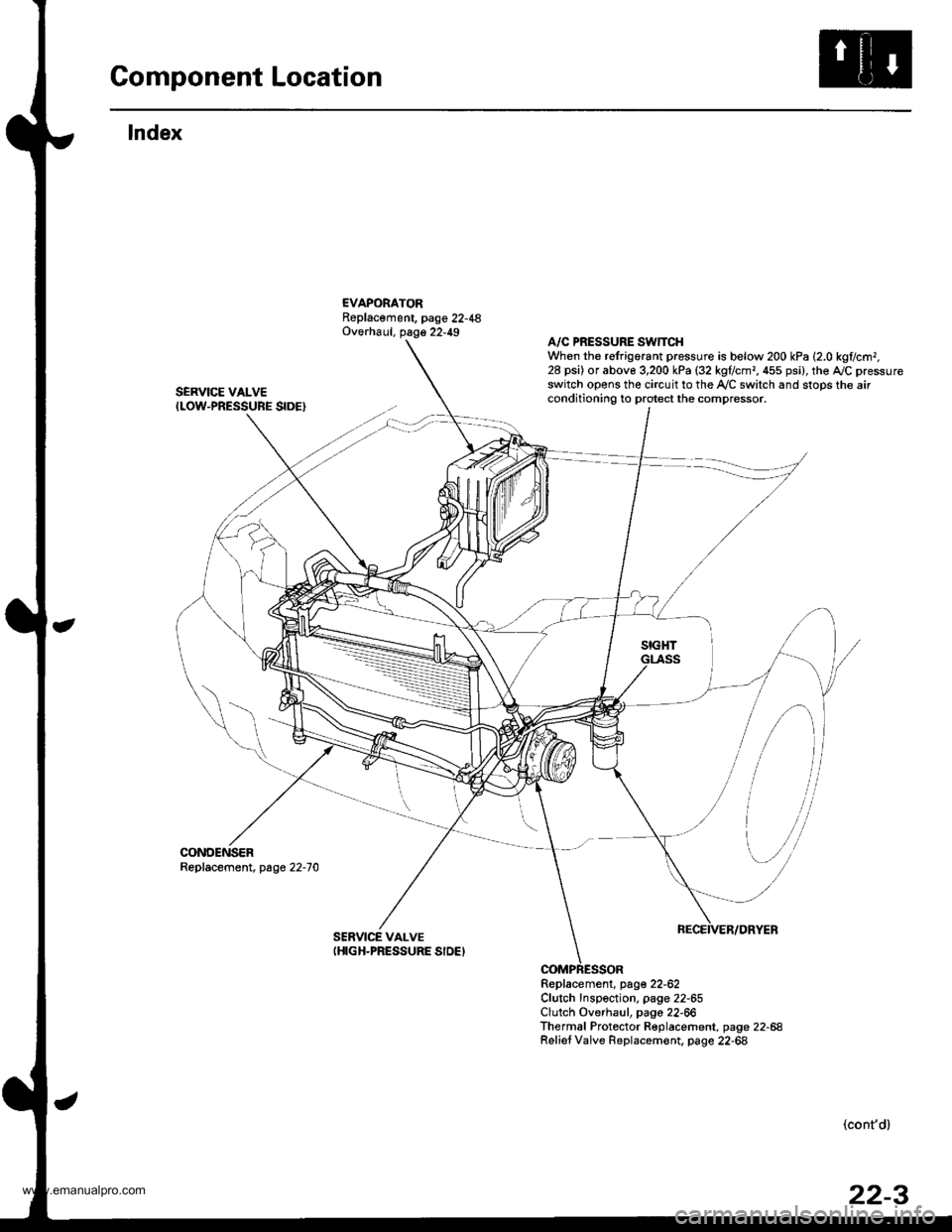
lndex
EVAPORATORReplacement, page 22-48Overhaul, page 22-49
SERVICE VALVEILOW-PRESSURE SIDE}
CONDENSERReplacement, page 22-70
A/C PRESSURE SWTTCHWhen the refrigorant pressure is below 200 kPa 12.0 kglc.r|r,28 psi) or abov€ 3,200 kPa (32 kgflcmr, 455 psi), the AJC pressureswitch opens the circuit to the Ay'C switch and stops the airconditioning to protect the compressor.
Replacement, page 22-62Clutch Inspection, page 22-65Clutch Overhaul, pago 22-66Thermal Protector Replacement, page 22-68Relief Valve Replacem€nt. page 22-68
SERVICE VALVEIHIGH-PRESSURE SIDEI
,
[\,
-il
(cont'd)
www.emanualpro.com
Page 1095 of 1395
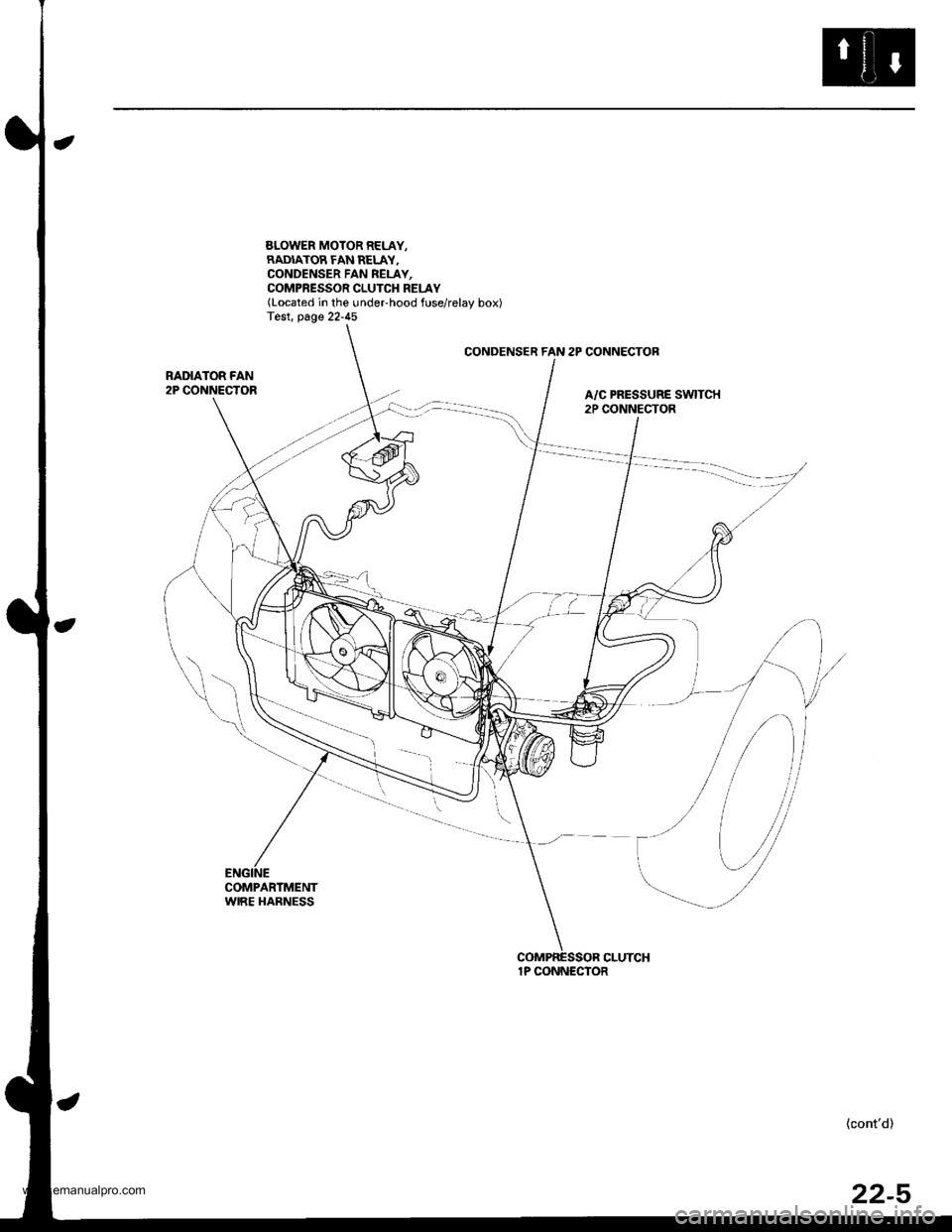
SLOWER MOTOR RELAY,RADIATOR FAN RELAY.CONDENSER FAN REI-AY,COMPRESSOR CLUTCH RELAY(Located in the undeFhood fuse/relay box)Test. page 22-45
CONDENSER FAN 2P CONNECTOB
RADIATOR FAN2P CONNECTORA/C PRESSURE SWITCH2P CONNECTOR
COMPARTMENTWIRE HARNESS
{cont'd)
1P CONNECTOR
22-5
www.emanualpro.com
Page 1097 of 1395
Description
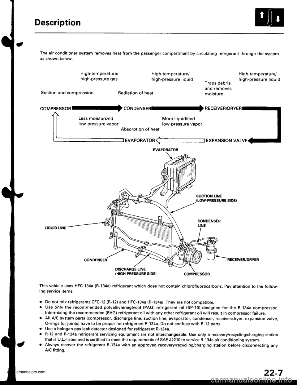
The air conditioner system removes heat from the passenger compartment by circulating refrigerant through the systemas shown below.
High'temperature/ High-temperature/
high-pressure gas h igh-pressure liquid
Suction and compression Radiation of heat
High-temperature/
high-pressu re liq uidr raps oeons,
and removes
motsture
More liquidified
row-pressure vapor
EVAPoRAToR (-l EXPANSToN vAL
SUCTION LINEtLow-PRESSURE S|OEt
LIOUID LINE
CONDENSER
coMpREssoR Il- coruoerusenl* necetve
Less moisturized
low-pressure vapor
Absorption of heat
DISCHARGE LINEIHIGH.PRESSURE SIDEI
This vehicle uses HFC-I34a (R-l34a) refrigerant which does not contain chlorofluorocarbons. Pay attention to the follow-ing service items:
. Do not mix refrigerants CFC-12 (R-12) and HFC-l34a (R-134a). They are not compatible.. Use only the recommended polyalkyleneglycol (PAG) refrigerant oil (SP-10) designed for the R-134a compressor.Intermixing the recommended (PAG) refrigerant oil with any other refrigerant oil will result in compressor failure.. Afl Ay'C system parts (compressor, discharge line. suction line, evaporator, condenser. receiver/dryer, expansion valve,O-rings for joints) have to be proper for refrigerant R-134a. Do not confuse with R-12 parts.
. Use a halogen gas leak detector designed for refrigerant R-134a.. R-12 and R-134a refrigerant servicing equipment are not interchangeable. Use only a recovery/recycling/charging stationthat is U.L.iisted and is certified to meet the requirements of SAE J2210 to service R-134a air conditioning system.. Always recover the refrigerant R-134a with an approved recovery/recycling/charging station before disconnecting anylVC fitting.
EVAPORAYOR
22-7
www.emanualpro.com