Diagnostic code HONDA CR-V 1999 RD1-RD3 / 1.G Workshop Manual
[x] Cancel search | Manufacturer: HONDA, Model Year: 1999, Model line: CR-V, Model: HONDA CR-V 1999 RD1-RD3 / 1.GPages: 1395, PDF Size: 35.62 MB
Page 204 of 1395

Fuel and Emissions
Special Tools ...................... 11-2
Component Locations
lndex ...................... ....,.... 11-3
Svstem Description
Vacuum Connections ...........,....,.,................. 1 1-9
Electrical Connections ................................... 1 1-15
System Connectors .,.,,.,............................,.,. 1 1-36
Troubleshooting
Troubleshooting Procedures,.,..................... 11-60
Engine Control Module/Powertrain ConttolModule Terminal Arrangement .............., 11-67
Diagnostic Trouble Code Chart .................... 1 t-75
How to Read Flowcharts .......,.....,.,............... I 1-79
PGM-Fl System
System Description .................,.,.,,,............... 1 1-80
Troubleshooting Flowcharts
Engine Control Module/PowertrainControl Module ........11-52
Manifold Absolute Pressure Sensor ............. 11-90
Intake Air Temperature Sensor .................... 1 1-95
Engine Coolant Temperature Sensor .,..,.,.... 1 1-99
Throttle Position Sensor ...........,.....,.,.,..,...... I 1'103
Primary Heated Orygen Sensor (Sensor 1) ... 11-110
Secondary Heated Oxygen Sensor{Sensor 2l .................. 1 1-117
Heated Oxygen Sensor Heater ..................... 11-121
Fuef Supply System ......11-124
Random Misfire ,....,.,..... 11-126
Mistire Detected in One Cylinder .....-........... 11-128
Knock Sensor ................ 11-130
CKP/TDC/CYP Sensor .................................... 1 1-131
Vehicle Speed Sensor ...............................,.... 1 1-135
Barometric Pressure Sensor .....,...,...,.,,........ 1 1-137
Electrical Load Detector ...,.,.......................... 1 1-138
CKF Sensor ................,.,, '11-112
ECM/PCM lnternaf Circuit ............................. 11'117
HO2S Replacement .,.,.,. 11-148
ldle Control System
System Description ............ 11-149
Troubleshooting Flowcharts
ldle Control System ...... 11-150
fdle Air Control Valve ......................,............. 11-152
Air Conditioning Signal ................................. I 1-155
Alternator FR Signal ...................................... 1 1-159
Starter Switch Si9na1 .................................... t l-161
Power Steering Pressure Switch Signal ...... 11-162
Brake Switch Si9na1 ...................................... 11-166
Fast ldle Thermo Valve .,.,.............................,.,.,. 11-168
ldle speed setting .............. 11-169
Fuel Supply System
Fuel Lines ............................ 11-171
Fuef Tube/Ouick-Conneci Fittings ..................... 11 -175
System Description ............ 11-178
Fuel Pressurg ...................... 11-178
Fuel Iniectors ................,..... 11-179
Fuel Pressure Re9u1ator .............................,.,...., f 1-181
Fuef Fifter ....,.,.,.,,,,.,............11-142
Fuel Pump ........................... 11-183
Fuel Gauge .......................... 11-184
Fuel Gauge Sending Unit ................................... I 1-185
Low Fuel Indicator System ...........,.,..,............... 1 1-185
PGM-FI Main Relay ............. 11-187
Fue|Tank................ ............. 11-191
Intake Air System
System Description ............ 11-193
Air Cleanel ,.,.,..................... 11-194
Throttle Cable ..................... 11-194
Throttle Body........ .............. 11-196
Emission Control System
System D$cription ...,....,.,. 11-199
Tailpipe Emission ............... 11-199
Three Way Catalytic Converter ..................,.,...,, 11-199
Positive Crankcase Ventilation System .,.,,,,.,.., 11-2O1
Evaporative Emission Controls .........,.,.,............ 11-203
www.emanualpro.com
Page 262 of 1395
Troubleshooting
Troubleshooting Procedures
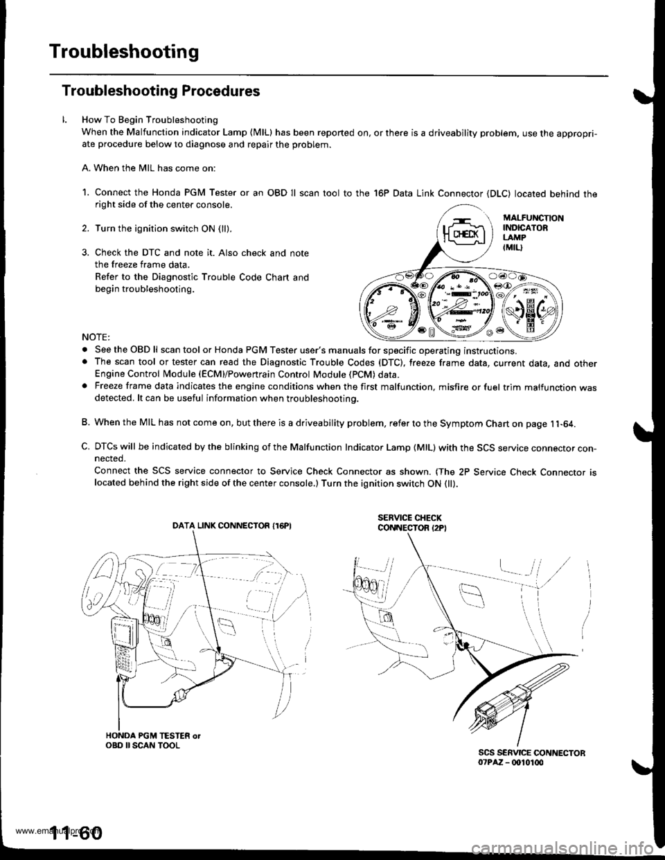
How To Begin Troubleshooting
When the Malfunction indicator Lamp (MlLl has been reported on, or there is a driveability problem, use the appropri-ate procedure below to diagnose and repair the problem.
A. When the MIL has come on:
1. Connect the Honda PGM Tester or an OBD Il scan tool to the 16P Data Link Connector (DLC) located behind theright side of the center console.
Turn the ignition switch ON (ll).
Check the DTC and note it. Also check and note
the freeze frame data.
Refer to the Diagnostic Trouble Code Chart and
begin troubleshooting.
NOTE:
. SeetheOBDll scan tool or Honda PGM Tester user's manuals for specific operating instructions.. The scan tool or tester can read the Diagnostic Trouble Codes (DTC), freeze frame data, current data, and otherEngine Control Module (ECM}/Powertrain Control Module (PCM) data.. Freeze frame data indicates the engine conditions when the first malfunction, misfire or fuel trim malfunction wasdetected. lt can be useful information when troubleshootino.
B. When the MIL has not come on, but there is a driveability problem, refer to the Symptom Chart on page 11-64.
C. DTCs will be indicated by the blinking of the Malfunction Indicator Lamp {MlL) with the SCS service connector con-nected.
Connect the SCS service connector to Service Check Connector as shown. {The 2P Service Check Connecror rslocated behind the right side of the center console.) Turn the ignition switch ON 0l).
DATA LINK CONNECTOR I16PI
1 1-60
www.emanualpro.com
Page 267 of 1395
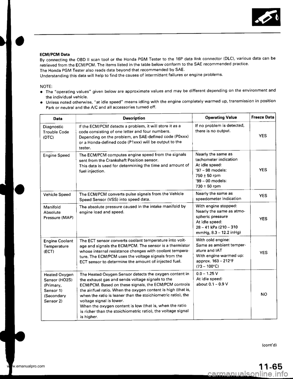
ECM/PCM Data
By connecting the OBD ll scan tool or the Honda PGM Tester to the 16P data link connector (OLC), various data can be
retrieved from the ECM/PCM. The items listed in the table below conform to the SAE recommended practice
The Honda PGM Tester also reads data beyond that recommended by SAE.
understanding this data will help to find the causes of intermittent failures or engine problems.
NOTE:
The ',operating values" given below are approximate values and may be different depending on the environment and
the individual vehicle.
Unless noted otherwise. "at idle speed" means idling with the engine completely warmed up, transmission in position
Park or neutral and the A,./C and all accessories turned otf.
DataDesc.iptionOp€rating ValuoFreeze Data
Diagnostic
Trouble Code
(DTC)
lf the ECM/PCM detects a problem, it will store it as a
code consisting of one letter and tour numbers
Depending on the problem, an SAE-defined code (Poxxx)
or a Honda-defined code (P'lxxx) will be output to the
tester.
lf no problem is detected,
there is no output.
YES
Engine SpeedThe ECN4/PCN4 computes engine speed from the signals
sent from the Crankshaft Position sensor.
This data is used for determining the time and amount of
fuel iniection.
Nearly the same as
tachometer indication
At idle speed:'97 - 98 models:
750 t 50 rpm'99 - 00 models:
730 f 50 rpm
YES
Vehicle SpeedThe ECM/PCM converts pulse signals from the Vehicle
Speed Sensor (VSSI into speed data.
Nearly the same as
speedometer indicationYES
Manifold
Absolute
Pressure (MAP)
The absolute pressure caused in the intake manifold by
engine load and speed.
With engin6 stopped:
Nearly the same as atmo-
spheric pressure
At idle speed:
2a - 41 kPa {210 - 310
mmHg, 8.3 - 12.2 inHg)
YES
Engine Coolant
Temperature
{ECT)
The ECT sensor converts coolant temperature into volt-
age and signals the ECM/PCM. The sensor is a thermistor
whose internal resistance changes with coolant tempera-
ture. The ECM/PCM uses the voltage signals from the
ECT sensor to determine the amount of injected fuel
With cold engine:
Same as ambient temPer-
ature and IAT
With engine warmed uP:
approx. 163 - 2'12'F
(73 - 100"c)
YES
Heated Oxygen
Sensor (HO25)
(Primary,
Sensor 1)
(Secondary
Sensor 2)
The Heated Oxygen Sensor detects the oxygen content in
the exhaust gas and sends voltage signals to the
ECMiPCM. Based on these signals, the ECM/PCM controls
the airlfuel ratio. When the oxygen content is high (that is.
when the ratio is leaner than the stoichiometric ratio), the
voltage signal is lower.
When the orygen content is low (that is, when the ratio
is richer than the stoichiometric ratio), the voltage signal
is higher.
0.0 - 1.25 V
At idle speed:
about 0.1 - 0.9
NO
(cont'd)
1 1-65
www.emanualpro.com
Page 277 of 1395
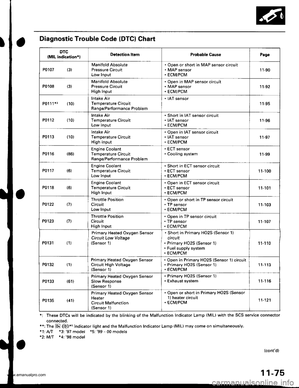
Diagnostic Trouble Code (DTCI Chart
*: These DTCS will be indicated by the blinking of the Malfunction Indicator Lamp (MlL) with the SCS service connector
connected.**: The E (E)*u indicator tight and the Malfunction Indicator Lamp (MlL) may come on simultaneously.*1' AIT *3 '97 model +5; '99 - 00 models*2: MlT *4:'98 model
{cont'd)
11-75
DTC(MlL indication*lDetection ltemProbable CausePago
P0107 (3)Manifold Absolute
Pressu.e CircuitLow Input
Open or short in MAP sensor circuit
MAP sensor
ECMiPCM
't 'l-90
P0108 {3)
Manifold AbsolutePressure Circuit
High Input
Open in MAP sensor circuitMAP sensor
ECM/PCM
11-92
P01 1 1*3 (10)Intake Air
Temperature Circuit
Range/Performance Problem
. IAT sensor
11-95
P0112 (10)lntake Air
Temperature CircuitLow Input
Short in IAT sensor circuit
IAT sensorECM/PCM1 1-96
P0113 (10)lntake Air
Temperature Circuit
High lnput
Open in IAT sensor circuit
IAT sensor
ECM/PCM
'I 1-97
P0116 (86)Engine CoolantTemperature CircuitRange/Performance Problem
ECT sensor
Cooling system1 1-99
P0117 (6)Engine Coolant
Temperature Circuit
Low Input
Short in ECT sensor circuit
ECT sensor
ECM/PCM
1 1-100
P0118 (6)Engine Coolant
Temperature CircuitHigh Input
Open in ECT sensor circujt
ECT sensor
ECM/PCM
11-101
P0122 \11
Throttle Position
Circuit
Low Input
Open or short in TP sensor circuitTP sensor
ECM/PCM
11-103
P0123 l7l
Throftle Position
Circuit
High Input
Open in TP sensor circuit
TP sensor
ECM/PCM11-107
P0131 (1)
Primary Heated Oxygen Sensor
Circuit Low Voltage(Sensor 1)
Short in Primary HO2S {Sensor 1)
circuit
Primary HO2S (Sensor 1)
Fuel supply system
ECM/PCM
1 1-1 10
P0132 (1)Primary Heated Orygen SensorCircuit High Voltage(Sensor 1)
Open in Primary HO2S (Sensor 1) circuitPrimary HO25 (Sensor 1)ECM/PCM
'11113
P0133 (61)Primary Heated Oxygen Sensor
Slow Response(Sensor 1)
. Primary HO2S (Sensor 1). Exhaust system11'I 16
P0135 (41)
Primary Heated Oxygen SensorHeater
Circuit Malfunction
{Sensor 1)
. Open or short in Primary HO2S (Sensor'l) heater circuit. ECM/PCM11-12'l
www.emanualpro.com
Page 278 of 1395
Troubleshooting
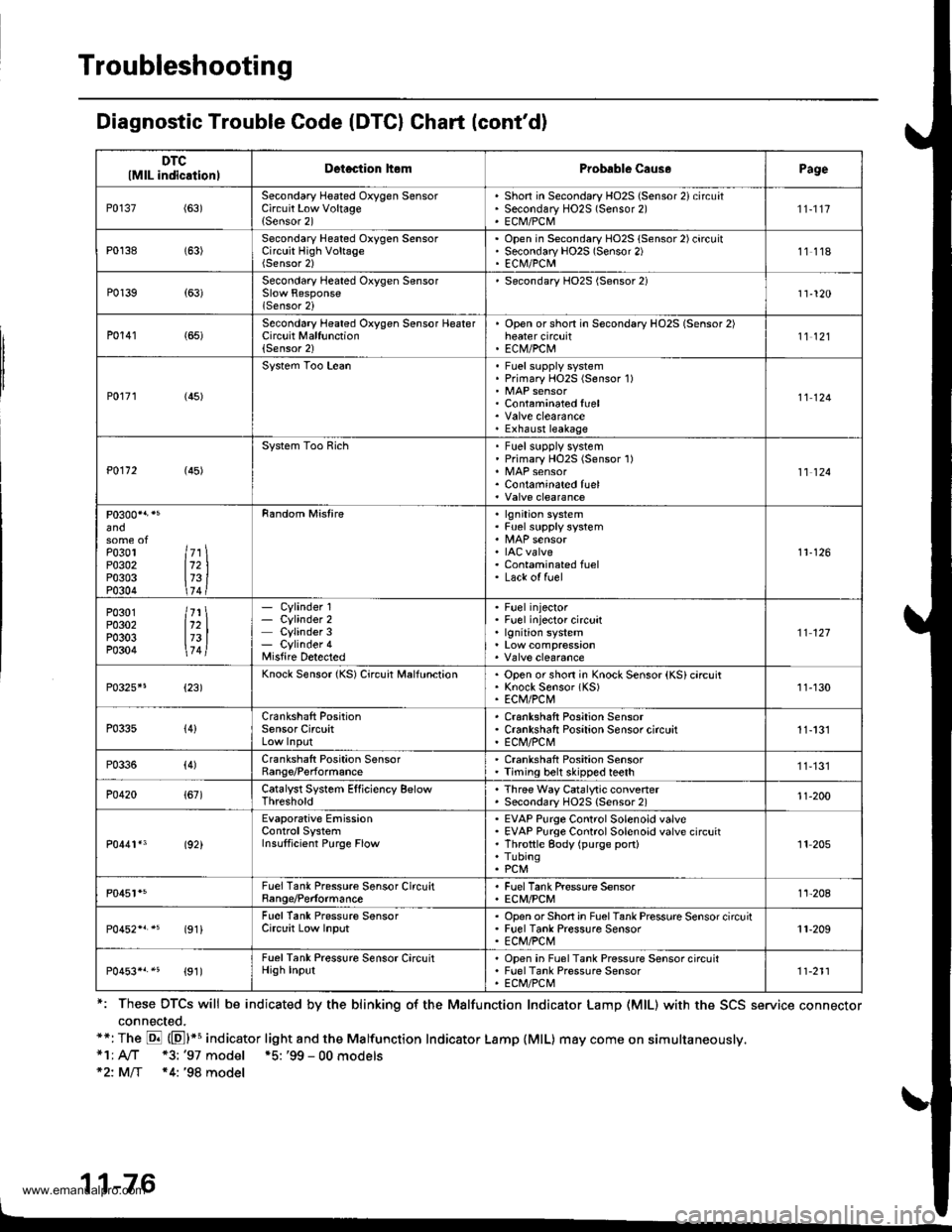
Diagnostic Trouble Code (DTCI Chart (cont'd)
*: These DTCS will be indicated by the blinking o{ the Malfunction Indicator Lamp (MlL) with the SCS service connector
connected.**: The E (El*s indicator light and the Malfunction Indicator Lamp {MlL) may come on simultaneously,*1; A/T *3: '97 model *5: '99 - 00 models*2: MlT *4: '98 model
11-76
DTClMlL indicationlDetection hemProbable Caus.Page
P0137(63)Secondary Heated Oxygen SensorCircuit Low Voltage{Sensor 2)
Shon in Secondary HO2S (Sensor 2) circuatSecondary HO2S (Sensor 2)ECM/PCM
'n-1t7
P0138 (63)Secondary Heated Oxygen SensorCircuit High VoltageOpen in Secondary HO2S (Sensor 2) circuitSecondary HO2S (Sensor 2)EC|\il/PCM11118
P0139{63)Secondary Heated Oxygen Sensor
lSensor 2i
Secondary HO2S (Sensor 2)11-120
P0141 (65)Second6ry Heated Oxygen Sensor HeaterCircuit Malfunction(Sensor 2)
Open orshon in Secondary HO2S (Sensor 2)heater circuitEC|V/PCtu11't2l
P0r71 (45)
System Too LeanFuel supply systemPrimary HOzS (Sensor 1)
Contaminated fuel
Exhaust leakage
11124
P0112 (45)
System Too RichFuel supplv systemPrimary HO2S (Sensor 1)
Contaminated fuel11 124
and
Po3ol ltr \P0302 112 |P0303 173 iP0304 \74 t
Random Mistirelgnition systemFuel supply system
IAC valveContaminated fuelLack of fuel
11-126
P0301 /71 \P0302 112 |P0303 173 |P0304 \7 4l
- Cylinder 1- Cylinder 2Cylinder 3- Cylinder 4Misfire Detected
Fuel injectorFuel injector circuitlgnition system't't 127
P0325*5{23)Knock Sensor {KS) Circuit MalfunctionOpen or shon in Knock Sensor (KS) circuitKnock Sensor (KS)ECM/PCt\411-130
P033s{4}Crankshaft PositionSensor CircuitCrankshaft Position SensorCrankshaft Positaon Sensor circuitE Cl\,l/PC l\,'!11-131
P0336(4)Crankshaft Position SensorRange/PerformanceCrankshaft Position SensorTiming belt skipped teeth11,131
P0420{67)Catalyst System Efficiency BelowThresholdThree Way Catalytic convenerSecondary HO2S {Sensor 2)'t1-200
P0441*3 (92)
Evaporative EmissionControlSystemInsulficient Purge Flow
EVAP Purge Control Solenoid valveEVAP Purge Control Solenoid valve circuitThrottle gody (purge port)TubingPCM
'It 205
P0451*5FuelTank Pressure Sensor CircuitBange/PerformanceFuel Tank Pressure SensorECM/PCMt't-208
(91iFuel Tank Pressure SensorCirclit Low InputOpsn orShort in FuelTank Pressure Sensor circuitFuel Tank Pressure SensorECM/PCt\411-209
P0453*r.5 {91)FuelTank Pressure Sensor CircuitHigh InputOpen in Fuel Tank Pressure Sensor circuitFuel Tank Pressure SensorECt /PCt\.111-211
www.emanualpro.com
Page 280 of 1395
Troubleshooting
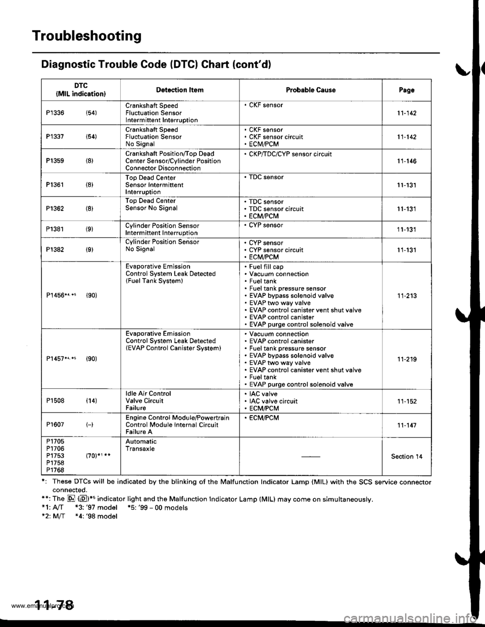
Diagnostic Trouble Code (DTCI Ghart (cont'd)
r: These DTCS will be indicated by the blinking oJ the Malfunction Indicator Lamp (MlL) with the SCS service connectorconnected.**: The Di (E)*5 indicator light and the Malfunction tndicator Lamp (MlL) may come on simultaneously.*1: A[f *3;'97 model *5: '99 - 00 models*21M/f *4: '98 model
11-78
DTC
{MlL indication}Detection ltemProbable CausePagc
P1336 154)Crankshaft SpeedFluctuation SensorIntermittent Interruption
. CKF sensor
11-142
P1337 i54)Crankshaft SpeedFluctuation SensorNo Signal
CKF sensorCKF sensor circuitECM,FCM11-142
P1359 (8)Crankshaft Position/Too DeadCenter Sensorrcylinder PositionConnector Disconnection
' CKP/TDC/CYP sensor circuit11-146
P1361 (8)Top Dead CenterSensor IntermittentInterruption11-131
P1362 (8)Top Dead CenterSensor No SignalTDC sensorTDC sensor circuitECM/PCM11-131
P1381 (9)Cylinder Position SensorIntermittent Interruption
. CYP sensor11-131
P1382 (9)Cylinder Position SensorNo SignalCYP sensorCYP sensor circuitECM/PCM11-131
P1456n.* {90}
Evaporative EmissionControl System Leak Detected(FuelTank System)
Fuelfill capVacuum connectionFueltankFuel tank prossure sensorEVAP bypass solenoid valveEVAP two way valveEVAP control canister vent shut valveEVAP control canisterEVAP purge controlsolenoid valve
11-213
Pr457n.s {90)
Evaporative EmissionControl System Leak Detected(EVAP Control Canister Svstem)
Vacuum connectionEVAP control canisterFuel tank pressure sensorEVAP bypass solenoid valveEVAP two way valveEVAP control canister vent shut valveFueltankEVAP purge controlsolenoid valve
11-219
P1508 (14)ldle Air ControlValve CircuitFailure
IAC valveIAC valve circuitECM/PCM11-152
Pr607(-)Engine Control Module,PowertrainControl Module Internal CircuitFailure A
. ECM,FCM11-147
P1705P1706P1753P1758P1768
AutomaticTransaxle
Section '14
www.emanualpro.com
Page 281 of 1395
How to Read Flowcharts
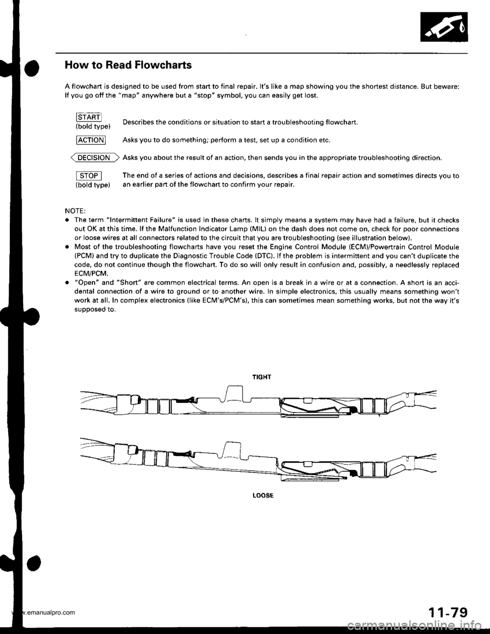
A flowchart is designed to be used from start to final repair. lt's like a map showing you the shortest distance. But beware:
lf you go off the "map" anywhere but a "stop" symbol, you can easily get lost.
brARn
t.-OotO tw"t Describes the conditions or situation to start a troubleshooting flowchart.
FcTloNl Asks you to do something; perform a test, set up a condition etc.
@ Asks you about the result of an action, then sends you in the appropriate troubleshooting direction.
fS-OPl The end of a series of actions and decisions, describes a final repair action and sometimes directs you to
(bold type) an earlier part of the flowchart to confirm your repair.
NOTE:
. The term "lntermittent Failure" is used in these charts. lt simply means a system may have had a failure, but it checks
out OK at this time. lf the Malfunction Indicator Lamp (MlL) on the dash does not come on, check for poor connections
or loose wires at all connectors related to the circuit that you are troubleshooting (see illustration below).
. Most of the troubleshooting flowcharts have you reset the Engine Control Module (EcM)/Powertrain Control Module(PCM) and try to duplicate the Diagnostic Trouble Code (DTC). lf the problem is intermittent and you can't duplicate the
code, do not continue though the flowchart. To do so will only result in confusion and, possibly, a needlessly replaced
ECM/PCM,
o "Open" and "Short" are common electrical terms. An open is a break in a wire or at a connection. A short is an acci-
dental connection of a wire to ground or to another wire. ln simple electronics, this usually means something won't
work at all. In complex electronics (like ECM'S/PCM'S), this can sometimes mean something works, but not the way it's
suooosed to.
LOOSE
11-79
www.emanualpro.com
Page 285 of 1395
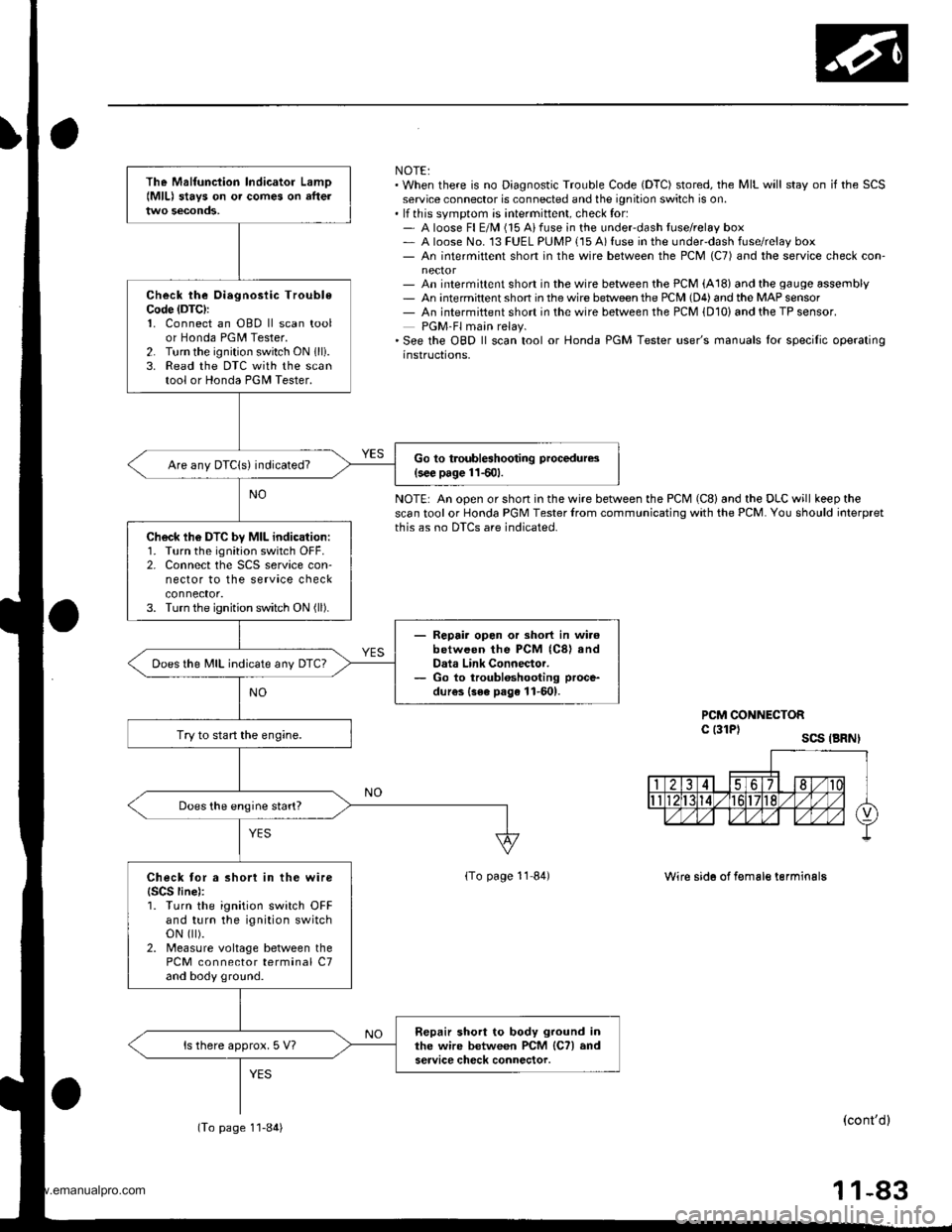
NOTE:. When there is no Diagnostic Trouble Code (DTC) stored, the MIL will stay on if the SCSservice connector is connected and the ignition switch is on.. lf this svmotom is intermittent, check for:- A loose Fl E/M (15 Aifuse in the underdash tuse/relay box- A loose No. 13 FUEL PUMP {15 A) fuse in the under-dash fuse/relay box- An intermittent short in the wire between the PCM (C7) and the service check con-
- An intermittent short in the wire between the PCM (A18) and the gauge assembly- An intermittent shon in the wire betlveen the PCM (D4) and the MAP sensor- An intermiftent short in the wire between the PCM {D10) and the TP sensor.PGM-Fl main relay.'See the OBD ll scan tool or Honda PGM Tester user's manuals lor specilic operatinginstructions,
NOTE: An open or short in the wire between the PCM (C8) and the DLC will keep thescan tool or Honda PGM Tester lrom communicating with the PCM. You should ioterpretthis as no DTCS are indicated.
PCM CONNECTORc l3lPl scs .BRNI
lTo page 11 84)Wire sid6 of f€male terminalg
(cont'dl
11-83
The Malfunciion lndicator Lamo{MlL) stavs on o. comes on afteltwo seconds,
Check the Oiegnosiic TroubleCode (DTC):
1. Connect an OBD ll scan toolor Honda PGM Tester.2. Turn the ignition switch ON 1lli.3. Read the DTC with the scantool or Honda PGII Tester.
Go to troubleshooting procedures(s€€ page 11501.Are any DTCIs) indicated?
Ch6ck lh6 DTC by MIL indication:1. Turn the ignition switch OFF.2. Connect the SCS service con-nector to the service checkconnector.3. Turn the ignition switch ON (ll).
- Repair opon or short in wi.6between the PCM (C8) andData Link Connector.- Go to troubloshooting proce-
dur€s {3ee page 11-601.
Does the MIL indicate any DTc?
Try to start the engine.
Does the engine start?
Check tor a short in the wire{SCS line):1. Turn the ignition switch OFFand turn the ignition switchoN flt).2. Measure voltage between thePCM connector terminal C7and body ground.
Repair short to body ground inthe wire between PCM lCTl andservice check connector.ls there approx. 5 V?
(To page 1'l-84)
www.emanualpro.com
Page 290 of 1395
PGM-FI System
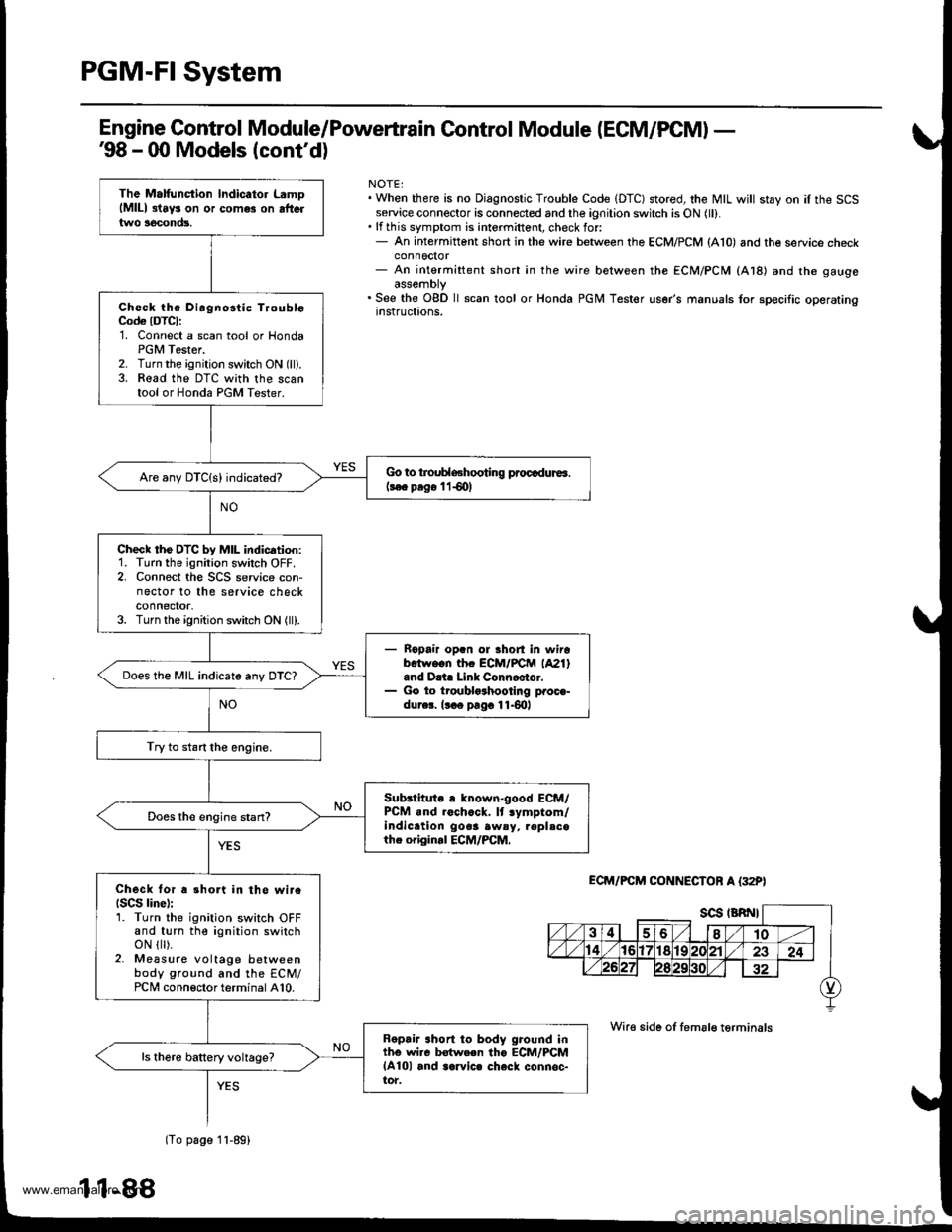
Engine Control Module/Poweftrain Control Module (ECM/PCM) -'98 - 00 Models (cont'dl
NOTE:. When there is no Diagnostic Trouble Code IDTC) stored, the MIL will stay on iI the SCSservice connector is connected and the ignition switch is ON (ll).. lf this symptom is intermittent, check for:- An intermittent short in the wire between the ECM/PCM (A10) and the service checkconnoctor- An intermittent short in the wire between the ECM/PCM (At8l and the gaugeassemDty. See the OgD ll scan tool or Honda PGM Tester user's manuals for specific operatingrnstructions.
ECM/FCM CONNECTOF A {32P)
Wire side of femsle t6rminals
The Malfunction lndicator LamolMlll 3lays on or comes on aftertwo 3econds.
Check the Dirgnostic TroubloCod€ (DTCI:'1. Connect a scan tool or HondaPGM Tester.2. Turn the ignition switch ON (ll).3. Read the DTC with the scantool or Honda PGM Tester.
Go to troublGhooting procadura.(3€c prg€ l lS0l
check tho DTc by MIL indication:1. Turn the ignition switch OFF.2. Connect the SCS service con-nector to the service checkconnector,3. Turn the ignition switch ON (ll).
Ropair op.n ol Bhort in wirob.twe.n thc ECM/FCtrl (A21)
and D.i. Link Connoctor.Go to troublo3hootlng proc€-dur6. lt o pag. 11.6lrl
Does the MIL indicate any DTC?
Try to start the engine.
Sub3titute r known"good ECM/PCM .nd roch.ck. lt .ymptom/indic.tion gooa awsy, repl.cothe origin.l ECM/PCM.
Does the engine stan?
Check tor a 3hort in the wireISCS linel:1. Turn the ignition switch OFFand turn the ignition switchoN { ).2- Measure voltage betweenbody ground and the ECM/PCi, conneclor terminal A10.
Ropria ahort to body ground intho wi.c Mwe.n tho ECM/PCMlA10l and aarvic. check connsc-tor.
lTo page 1l-89)
11-88
www.emanualpro.com
Page 292 of 1395
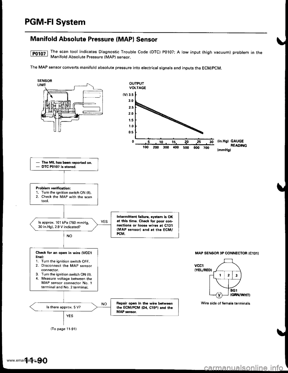
PGM-FI System
Manifold Absolute Pressure (MAPI Sensor
The scan tool indicates Diagnostic Trouble Code (DTC) POl07: A low input (high vacuum) problem in theManifold Absolute Pressure (MAP) sensor,
The MAP sensor convens manifold absolute pressure into electrical signals and inputs the ECM/pCM.
OUTPUIVOLTAGE
tvl3.s
3.0
2.5
2.O
1.5
1.0
0.5
o .5 ro- 15^ 1olin.H9) GAUGEREADIT{G
lmmHgl
3025
100 200 300 a00 5oo 6fi, 7d)
MAP SENSOR 3P CONNECTOR IC131I
vccl(YEL/RED}
Th6 MIL has b€en reoorted on.DTC P0107 is 3tored.
Problom verification:1. Turn the ignition switch ON lll).2. Check the lvlAP with the scanroot.
lrtormittem tailu.e, lystam b OKat thb timo. Check tor poor con-noctions or loosa wird at C131(MAP rensor) and rt the ECM/PCM.
ls approx. 101 kPa (760 mmHg,30 in.Hg),2.9 V indicated?
Check for an op6n in wi.o IVCC1linel:1. Turn the ignition switch OFF.2. Disconnect the MAP sensorconnector,3. Turn the ignition switch ON {ll}.4. Measure voltage between theMAP sensor connector No. 1termanal and No. 2 terminal.
Roprir op€n in the wir6 bstweentho ECM/PCM (D4, C19*l and theMAP sensor.
ls there approx. 5 V?
(To page 11-91)
11-90
Wiro side ol temale terminals
www.emanualpro.com