EWD HONDA CR-V 1999 RD1-RD3 / 1.G Workshop Manual
[x] Cancel search | Manufacturer: HONDA, Model Year: 1999, Model line: CR-V, Model: HONDA CR-V 1999 RD1-RD3 / 1.GPages: 1395, PDF Size: 35.62 MB
Page 62 of 1395
Starting System
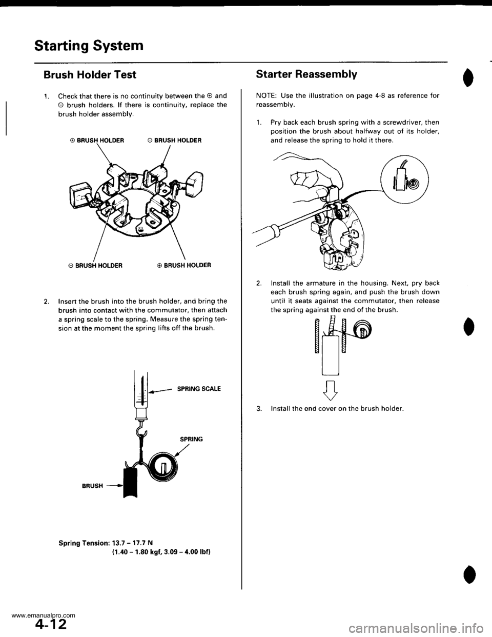
Brush Holder Test
1. Check that there is no continuity between the O and
O brush holders. lf there is continuitv, replace the
brush holder assembly.
O BRUSH HOLDER@ BRUSH HOLDER
Insert the brush into the brush holder, and bring the
brush into contact with the commutator, then attach
a spring scale to the spring. Measure the spring ten-
sion at the moment the spring lifts off the brush.
SPRING SCALE
Spring Tension: 13.7 - 17.7 N
(1.40 - 1.80 kgf, 3.09 - 4.00 lbf)
4-12
Starter Reassembly
NOTE: Use the illustration on page 4I as reference for
reassemDty.
1. Pry back each brush spring with a screwdriver, then
position the brush about halfway out ol its holder,
and release the spring to hold it there.
2. Install the armature in the housing. Next, pry back
each brush spring again, and push the brush down
until it seats against the commutator, then release
the spring against the end of the brush.
- E^
F*4#-@
6t taal la
tlll
3. Install the endon the brush holder.
ft
cover
www.emanualpro.com
Page 135 of 1395
Camshafts
4.
Inspection
1.
7.
Loosen the adjusting screws.
Remove the camshaft holders.
Mark the rocker arms, then remove them.
Reinstall the camshaft and holders. Tighten the
camshaft holder bolts in a crisscross pattern, begin-
ning with the inner bolts.
9.8 N.m (1.0 kgf.m.7.2 lbf.ft)
Seat the camshafts by pushing them toward the dis-
tributor end of the head with a screwdriver.
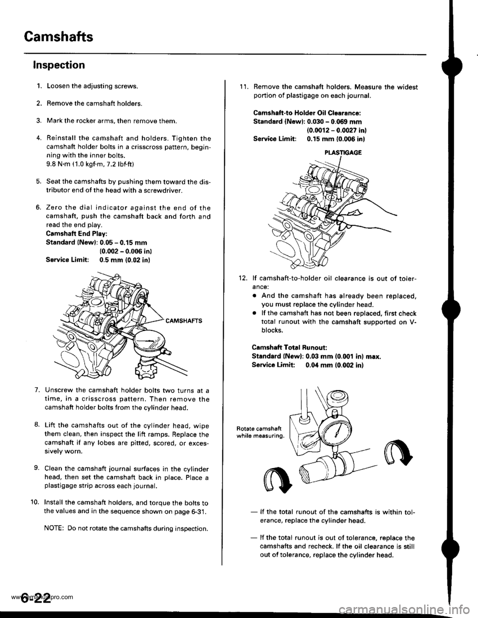
Zero the dial indicator against the end of the
camshaft, push the camshaft back and forth and
read the end play.
Camshaft End Play:
Standard lNewl: 0.05 - 0.15 mm
10.002 - 0.005 in)
Service Limit: 0.5 mm (0.02 in)
Unscrew the camshaft holder bolts two turns at a
time, in a crisscross pattern, Then remove the
camshaft holder bolts from the cvlinder head.
Lift the camshafts out of the cylinder head. wipe
them clean, then inspect the lift ramps, Replace the
camshaft if any lobes are pitted, scored, or exces-
sively worn.
Clean the camshaft journal surfaces in the cylinder
head, then set the camshaft back in Dlace. Place aplastigage strip across each journal.
Install the camshaft holders. and torque the bolts tothe values and in the sequence shown on page 6-31.
NOTE: Do not rotate the camshafts during inspection.
8.
10.
6-22
11. Remove the camshaft holders. Measure the widest
portion of plastigage on each journal.
Camshatt-to HoldGr Oil Clearance:
Standard {Newl: 0.030 - 0.069 mm
{0.0012 - 0.0027 in}
Servico Limit: 0.15 mm (0.006 in)
12. lf camshaft-to-holder oil clearance is out of toler-
ance:
. And the camshaft has already been replaced,
you must replace the cylinder head.. lf the camshaft has not been replaced, first check
total runout with the camshaft suoDorted on V-
blocks.
Camshaft Total Runout:
Standard (N6w): 0.03 mm (0.001 in) max.
Service Limit 0.04 mm (0.(X)2 in)
Rotat6 camshattwhile measuring.
- lf the total runout of the camshafts is within tol-
erance, replace the cylinder head
- lf the total runout is out of tolerance, replace the
camshafts and recheck. lf the oil clearance is still
out of tolerance, replace the cylinder head.
www.emanualpro.com
Page 708 of 1395
Valve Body
Repair
NOTE: This repair is only necessary if one or more ofthe valves in a valve body do not slide smoothly in theirbores. Use this procedure to free the varves.
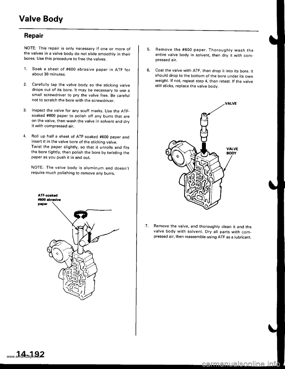
'1. Soak a sheet of #600 abrasive paper in ATF forabout 30 minutes.
2. Carelully tap the valve body so the sticking valvedrops out of its bore. lt may be necessary to use asmall screwdriver to pry the valve free. Be carefulnot to scratch the bore with the screwdriver.
4.
Inspect the valve for any scutf marks. Use the ATF-soaked #600 paper to polish off any burrs that areon the valve, then wash the valve in solvent and dryit with compressed air.
Roll up half a sheet of ATF-soaked #600 paper andinsert it in the valve bore of the sticking valve.Twist the paper slightly, so that it unrolls and fitsthe bore tightly, then polish the bore by twisting thepaper as you push it in and out.
NOTE: The valve body is aluminum and doesn,trequire much polishing to remove any ourrs.
,l
14-192
5.Remove the #600 paper. Thoroughly wash theentire valve body in solvent, then dry it with com-pressed ar.
Coat the valve with ATF, then drop it into its bore, ltshould drop to the bottom of the bore under its ownweight. lf not, repeat step 4, then retest. lf the valvestill sticks, replace the valve body.
Remove the valve. and thoroughly clean it and thevalve body with solvent. DrV all parts with com-pressed air, then reassemble using ATF as a lubricant.
1.
w
www.emanualpro.com
Page 709 of 1395
Valve
Assembly
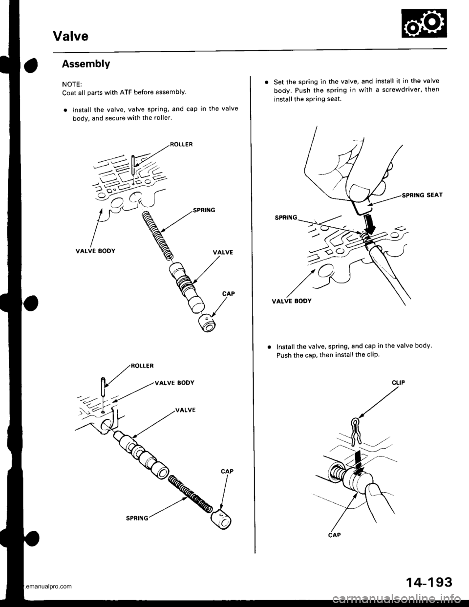
NOTE;
Coat all parts with ATF before assembly.
. lnstall the valve, valve spring, and cap in the valve
body. and secure with the roller.
VALVE BODY
VALVE
. Set the spring in the valve, and install it in the valve
body. Push the spring in with a screwdriver, then
install the spring seat.
SEAT
VALVE EODY
Install the valve, spring, and cap in the valve body.
Push the caD, then install the cliP.
u>o
CAP
14-193
www.emanualpro.com
Page 725 of 1395
One-way Glutch
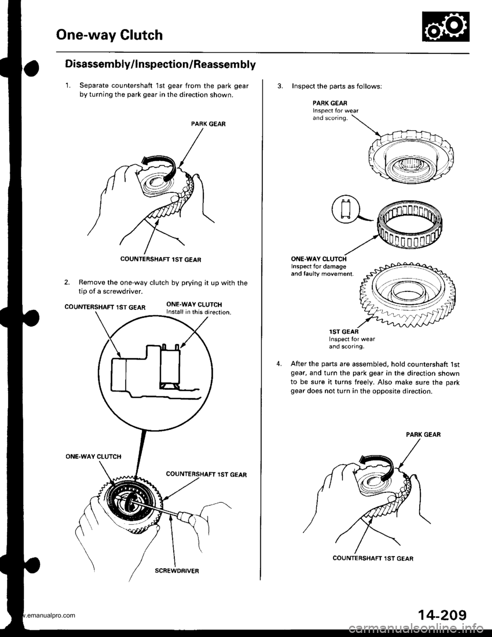
Disassembly/lnspection/Reassem bly
1. Separate countershaft 1st gear from the park gear
by turning the park gear in the direction shown.
PARK GEAR
2. Remove the one-way clutch by prying it up with the
tip of a screwdriver.
COUNTERSHAFT IST GEARONE.WAY CLUTCHInstall in this direction.
ONE.WAY CLUTCH
lST GEAR
COUNTERSHAFT lST GEAR
SCREWDRIVER
14-209
3. Inspect the oarts as follows;
PARK GEARInspect Ior wearand sconng.
ONE.WAY CLUTCHInspect for damageand taulty movement,
4.
lST GEARInspect for wearand scortng.
After the parts are assembled, hold countershaft lstgear. and turn the park gear in the direction shown
to be sure it turns freely. Also make sure the park
gear does not turn in the opposite direction.
COUNTERSHAFT ,IST GEAR
www.emanualpro.com
Page 736 of 1395
Clutch
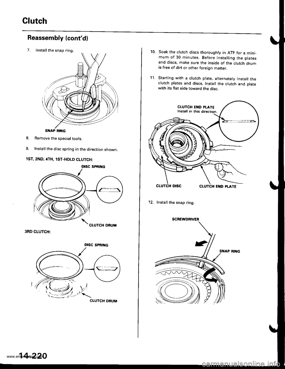
Installthe snap ring.
Reassembly (cont'd)
7.
S AP RIIG
8. Remove the special tools.
9, Install the disc spring in the direction shown.
1ST, 2ND, 4TH, lST-HOLD CLUTCH:
3RD CLUTCH:
Dlsc sPRrrtc
CIUTCH ORUM
otsc sPfitl{c
14-220
10.Soak the clutch discs thoroughly in ATF for a mini_mum of 30 minutes. Before installing the platesand discs, make sure the inside of the clutch drumis free of din or other foreign matter
Starting with a clutch plate, alternatelv install theclutch plates and discs. Install the clutch end platewith its flat side toward the disc.
CLUTCH EI{D PI.ATEInstall in this directior.
CLUTCHCLUTCH EI{D PLATE
12. Install the snap ring.
SCREWDRIVER
't1.
www.emanualpro.com
Page 807 of 1395
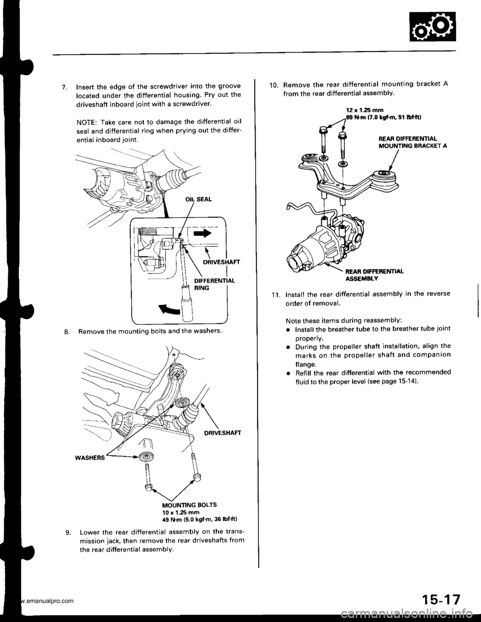
7. Insert the edge of the screwdriver into the groove
located under the differential housing Pry out the
driveshaft inboard ioint with a screwdraver.
NOTE: Take care not to damage the differential oil
seal and differential ring when prying out the differ-
ential inboard joint.
8. Remove the mounting bolts and the washers.
DRIVESHAFT
MOUNTING BOLTS'10 x 1 .25 mm,19 N'm (5 0 kgf m, 36 lbtftl
Lower the rear differential assembly on the trans-
mission jack, then remove the rear driveshafts from
the rea r difterential assembly.
DIFFERENTIAL
12 x 1.25 fifi
10. Remove the rear difterential mounting bracket A
from the rear differential assembly.
N.m {7.0 lgf.m. 5l lbl.tt)
REAR DIFFERENTIALMOUNTING BRACKET A
REAN DFFERENTI,ALASSEMBLY
11.Install the rear differential assembly in the reverse
order of removal.
Note these items during reassembly
. lnstall the breather tube to the breather tube joint
properly.
. During the propeller shaft installation, align the
marks on the propeller shaft and companion
flange.
. Reiill the rear differential with the recommended
fluid to the proper level {see page 15-14).
15-17
www.emanualpro.com
Page 820 of 1395
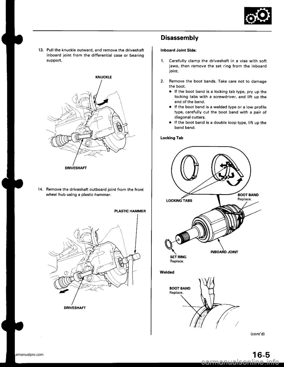
13, Pull the knuckle outward, and remove the driveshaft
inboard joint from the differential case or bearing
suoDort.
KNUCKLE
Remove the driveshaft outboard joint from the front
wheel hub using a plastic hammer.
PLASTIC HAMMER
14.
DRIVESHAFT
DRIVESHAFT
Disassembly
Inboard Joint Sid€:
1, Carefully clamp the driveshaft in a vise with softjaws, then remove the set ring from the inboardjoint.
2. Remove the boot bands. Take care not to damage
the boot,
. lf the boot band is a locking tab type, pry up the
locking tabs with a screwdriver, and lift up the
end of the band.
. lf the boot band isawelded typeora low profile
type, carefully cut the boot band with a pair of
diagonal cutters.
. lf the boot band is a double loop type. lift up the
band bend.
Locking Tab
SET BINGReplace.
Welded
{cont'd)
16-5
www.emanualpro.com
Page 822 of 1395
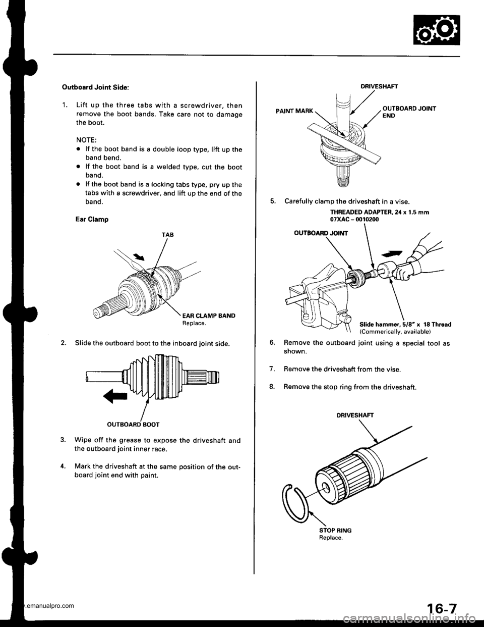
Outboard Joint Side:
1. Lift up the three tabs with a screwdriver, then
remove the boot bands, Take care not to damage
the boot.
NOTE:
. lf the boot band is a double loop type, lift up the
band bend.
. lf the boot band is a welded type, cut the boot
band.
. lf the bootband isa lockingtabstype. pry upthe
tabs with a screwdriver, and lift up the end of the
oano.
Ear Clamp
EAR CLAMP BANDReplace.
2. Slide the outboard boot to the inboard ioint side.
Wipe off the grease to expose the driveshaft andthe outboard joint inner race.
Mark the driveshaft at the same position of the out-
board joint end with paint.
TAB
DRIVESHAFT
PAINT MARK
5, Carefullv clamD the driveshaft in a vise.
THREADED AOAPTER,2iI x 1.5 mm07xAc - 0010200
Remove the outboard joint using a special tool asshown.
Remove the driveshatt trom the vise
Remove the stop ring from the driveshaft.
o.
7.
8.
STOP RINGReplace.
Slide hammc..5/8'x lS Throad(Commerically, available)
DRIVESHAFT
www.emanualpro.com
Page 1009 of 1395
Mirrors
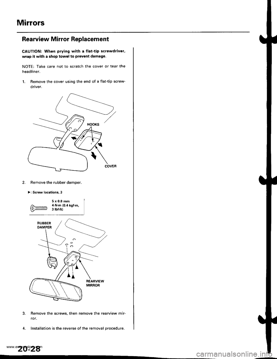
Rearview Mirror Replacement
CAUTION: When prying with a flat-tip screwdrivor,
wrap it whh a shop towel to prevent damage.
NOTE: Take care not to scratch the cover or tear the
headliner.
1. Remove the cover using the end of a flat-tip screw-
drtver.
Remove the rubber damper.
>: Screw locations,3
Remove the screws, then remove the rearview mir-
ror.
Installation is the reverse of the removal procedure.
20-28
HOOKS
www.emanualpro.com