Engine cylinder installation HONDA CR-V 1999 RD1-RD3 / 1.G Workshop Manual
[x] Cancel search | Manufacturer: HONDA, Model Year: 1999, Model line: CR-V, Model: HONDA CR-V 1999 RD1-RD3 / 1.GPages: 1395, PDF Size: 35.62 MB
Page 41 of 1395

Lubrication Points
For the details of lubrication points and type of lubricants to be applied. refer to the illustrated index and various work pro-
cedures (such as Assembly/Reassembly, Replacement, Overhaul, Installation, etc.) contained in each section.
Recomm6nded Engine OilEngine oil viscosity for ambient temperature ranges
100'F
-30 -20 .10 0 10 20 30 40'c
r1: Always use Genuine Honda Manual Transmission Fluid {MTF). Using motor oil can cause stiffer shifting because it
does not contain the orooer additives.*2: Always use Genuine Honda Premium Formula Automatic Transmission Fluid (ATF). Using a non-Honda ATF can affect
shift qualitv.+3r Always use Genuine Honda DOT 3 Brake Fluid. Using a non-Honda brake fluid can cause corrosion and decrease the
life of the system.*4: Always use Genuine Honda Power Steering Fluid. Using any other type of power steering fluid or automatic transmis-
sion fluid can caused increased wear and poor steering in cold weather.
API SERVICE LABEL
/,.*-G\
/.'z-\e\t/6AE\ll-;-1 5w-30 /---l
w
API CERTIFICATION SEAL
ffi-20 0 20
NO.LUBRICATION POINTSLUBRICANT
EngineAPI Service Grade: Use SJ "Energy Conserving" grade oil. The oilcontainer may also display the API Certitication seal shownbelow. Make sure it says "For Gasoline Engines." SAE vjscosity:See chart below.
2
TransmissionManualGenuine Honda MTF*1
AutomaticGenuine Honda Premium Formula Automatic Transmission Fluid(ATF)*'
3Rear differentialGenuine Honda CVT Fluid
4Brake line (includes ABS line)Genuine Honda DOT 3 Brake Fluid*3
5Clutch LineBrake fluid DOT 3 or DOT 4*3
6Shift lever pivots (Manual transmission)Grease with molybdenum disultide
1Release fork (Manual transmission)LJrea Grease UM264 P/N 4'1211 - PYs - 305
IPower steering gearboxSteering grease P/N 08733 - B070E
Throttle cable end {Dashboard lower panel holelSilicone grease
10l112
14
Throttle cable end (Throttle link)Brake master cylinder pushrodPedal linkageBattery terminalsFuelfill lidClutch master cylinder pushrod
Multi purpose grease
1617181920
Hood hinges and hood lockTailgate hingesHatch glass hingesDoor hinges, upper and lowerDoor opening detent
Honda White Lithium Grease
21
22
Caliper Piston seal, Dust seal,Caliper pin, PistonShilt cable and select cable {Manual transmission)Silicone grease
23Brake line ioints (Front and rear wheelhouse)Rust preventives
24Power steering systemGenuine Honda Power Steering Fluid-.
25Air conditioning compressorCompressor oil: SP 10 lP/N 38897 - P13 - A0lAH or38899-P13-A01)For Refrigerant: HFC 134a (R,134a)
3-2
www.emanualpro.com
Page 128 of 1395
-?E
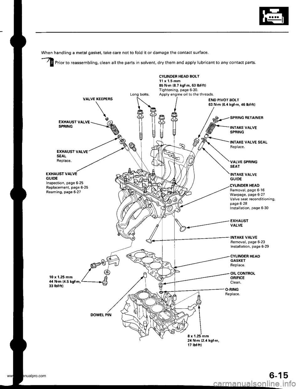
handling a metal gasket. take care not to fold it or damage the contact surface.
Prior to reassembling, clean all the parts in solvent, dry them and apply lubricant to any contact parts.
CYLINDER HEAD BOLT11 x 1.5 mm85 N.m {8.7 kgf.m,6:} lbf.ft)Tightening, page 6'30.Apply engine oilto the threads.VALVEKEEPERS
\
END PIVOT BOLT63 N.m 16.4 kgl m, 46 lbf.ft)
EXHAUSY VALVESEALReplace.
EXHAUST VALVEGUIDEInspection, page 6-25Replacem6nt, page 6-25Reaming, page 6-27
10 x 1.25 mm4,0 N.m {i1.5 kgf.m.33 rbf.ft)
GASKETReplace.
OIL CONTROLORIFICEClean.
EXHAUST VALVESPRING
SPRING BETAINER
INTAKE VALVESPRING
INTAKE VALVE SEALReplace.
VALVE SPRINGSEAT
INTAKE VALVEGUIDE
Removal, page 6-16Warpage, page 6 27Valve seat reconditioning,page 6 28Installation, page 6-30
EXHAUSTVALVE
INTAKE VALVERemoval, page 6-23Installation, page 6-29
CYLINDER HEAO
HEAD
O.RINGReplace.
8 x 1.25 mm24 N.m (2.4 kgf.m,17 tbf.ft)
DOWEL PIN
6-15
www.emanualpro.com
Page 143 of 1395
Cylinder Head
Installation
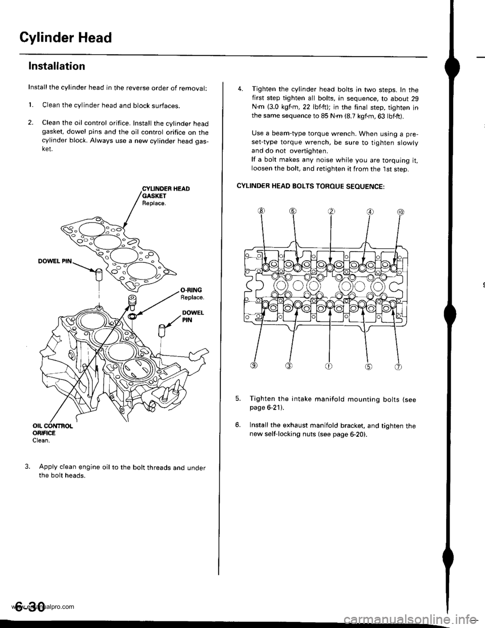
Installthe cylinder head in the reverse order of removal:
1. Clean the cylinder head and block surfaces.
2. Clean the oil control orifice. Install the cylinder headgasket, dowel pins and the oil control orifice on thecylinder block. Always use a new cylinder head gas-ket.
CYLII{DER HEADGASKETR€place.
DOWEL PIN
O.RINGRoplace.
DOWELPIN
OIL CONTBOLORIFICEClean.
Apply clean engine oil to the bolt threads and underthe bolt heads.
4. Tighten the cylinder head bolts in two steps. In thefirst step tighten all bolts, in sequence, to about 29
N.m {3.0 kgf.m,22 lbf.ft); in the finat step, tighten inthe same sequence to 85 N.m (8.7 kgf.m,63 lbf.ft).
Use a beam-type torque wrench. When using a pre-
set-type torque wrench, be sure to tighten slowly
and do not overtighten.
lf a bolt makes any noise while you are torquing it,loosen the bolt, and retighten it from the 1st step.
CYLINDER HEAD BOLTS TOROUE SEOUENCE:
Tighten the intake manifold mounting bolts (see
page 6-21).
Install the exhaust manifold bracket. and tighten thenew self-locking nuts (see page 6-20).
6-30
www.emanualpro.com
Page 147 of 1395
Engine Block
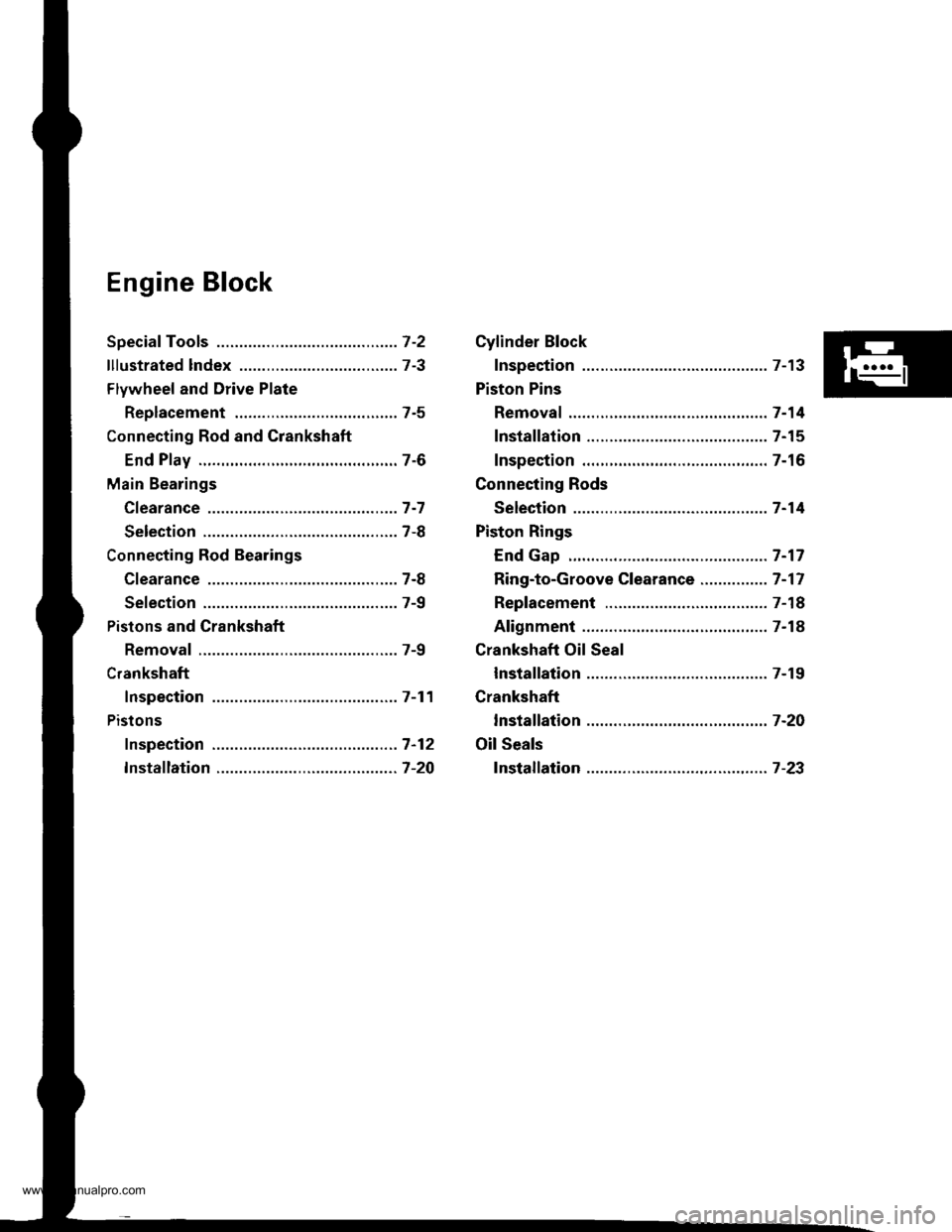
Speciaf Tools .............7-2
lllustrated lndex ................................... 7-3
Flywheel and Drive Plate
Replacement ..,.,....7-5
Connecting Rod and Grankshaft
End Play .................7-6
Main Bearings
Cfearance ...............7 -7
Selection ................7-8
Connecting Rod Bearings
Clearance ...............7-8
Selection ................7-9
Pistons and Crankshaft
Removal .................7-9
Crankshaft
Inspection .............. 7-11
Pistons
fnspection ..............7-12
fnstaflation .............7-20
Cylinder Block
Inspection ..............7-13
Piston Pins
Removal ..,.......,,..... 7-14
Installation ............. 7-15
Inspection .............. 7-16
Connecting Rods
Selection ................7 -14
Piston Rings
End Gap .................7 -17
Ring-to-Groove Clearance ............... 7 -17
Replacement .........7-18
Alignment .............. 7-18
Crankshaft Oil Seal
lnstallation ............. 7-19
Crankshaft
lnstalfation .............7-20
Oil Seals
fnstalfation ....,..,.....7-23
www.emanualpro.com
Page 150 of 1395
lllustrated Index (cont'd)
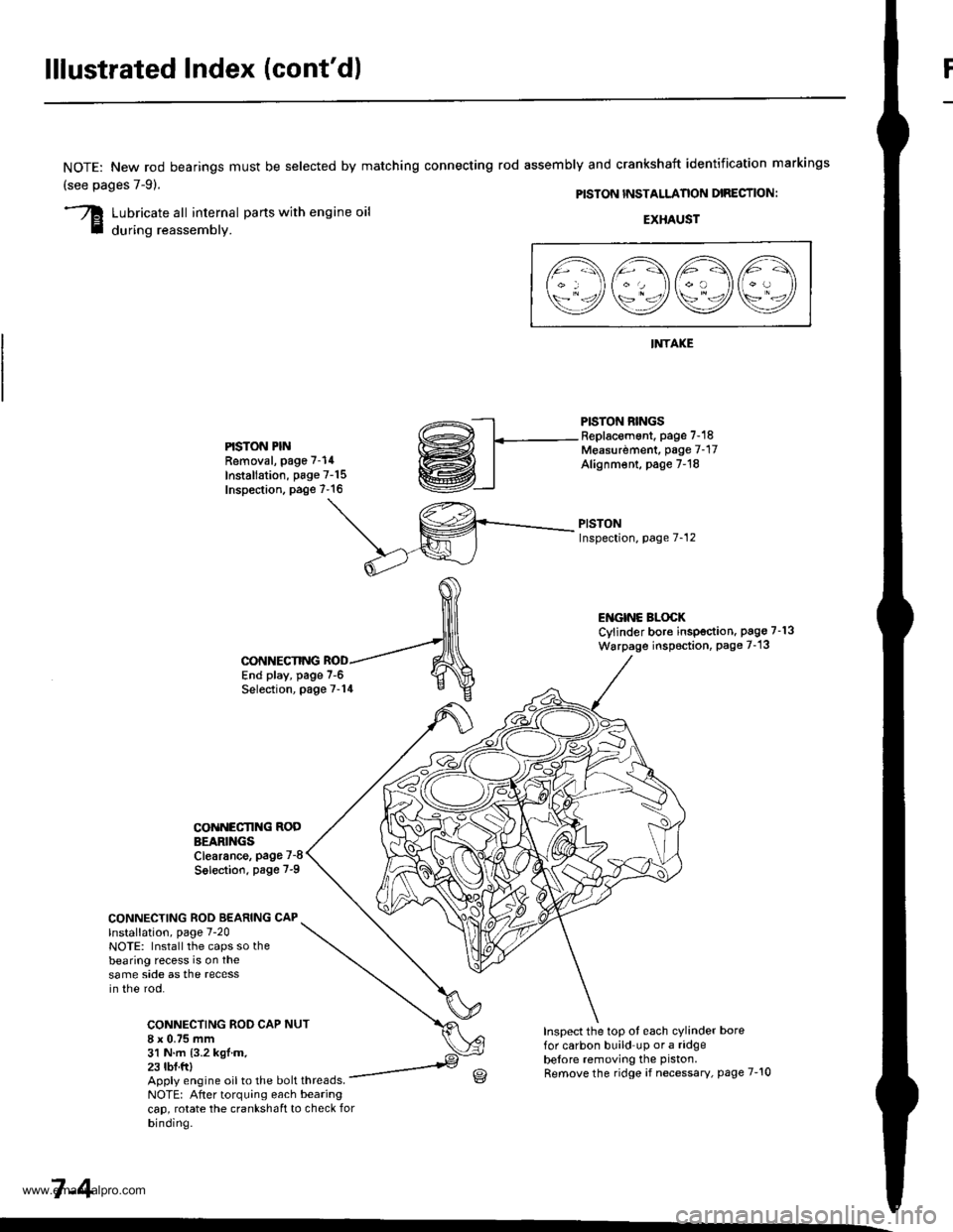
NOTE: New rod bearings
(see pages 7-91.
must be selected by matching connecting rod assembly and crankshaft identification markings
PISTON INSTALLANON DIRECTION:
Lubricate all internal parts with engine oil
during reassembly.EXHAUST
INTAKE
PISTON RINGSReplacement. page 7-18Measurdment, page 7-17Alignm€nt, page 7-18
PISTONInspection, page 7-12
l1\AAtr\
\9q9Q9e/
PISTON PINRemoval, page 7-14
Installation, page 7-15Inspection. page 7-16
ENGINC BLOCKCylinder bore inspection. pago 7-13
Warpage inspoction, Page 7-'13
CONNECTING ROD BEARING CAPlnstallation, page 7-20NOTE: Install the caps so thebearing recess is on thesame side as the recessin the rod.
CONNECTING ROD CAP8 x 0.75 mm31 N.m {3.2 kgl.m.23 tbf.ftl
CONNECTING
COiINECI'ING RODBEARINGSClearance, page 7-8
Solection. page 7-9
NUT
End play, page 7-6Selection, page 7-14
Inspect the top ot each cylinder borefor carbon build up or a ridgebelore removing the piston.
Remove the ridge if necessary, page 7-10Apply engine oil to the bolt threads.NOTE: After torquing each bearingcap, rotate the crankshaft to check forbinding.
7-4
www.emanualpro.com
Page 166 of 1395
PistonsCrankshaft
Installation
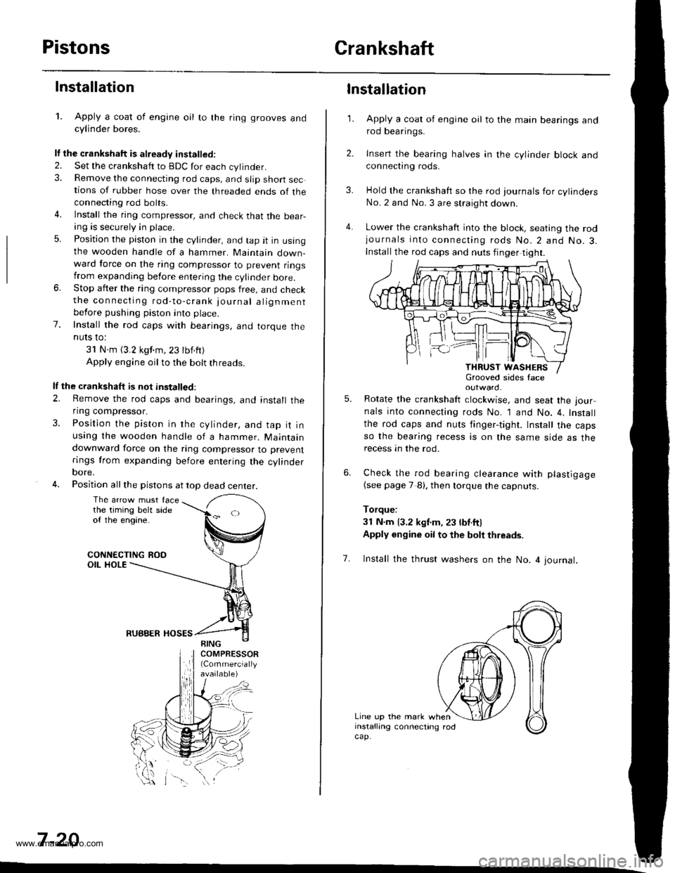
1. Apply a coat of engine oil to the ring grooves andcylinder bores.
It the crankshaft is already installed.
2. Set the crankshatt to BDC for each cylinder.3. Remove the connecting rod caps, and slip short sections of rubber hose over the threaded ends of theconnecting rod bolts.
4. lnstall the ring compressor, and check that the bear-ang is securely in place.
5. Position the piston in the cylinder, and tap it in usingthe wooden handle of a hammer. Maintain down-ward force on the ring compressor to prevent ringstrom expanding before entering the cylinder bore.6. Stop after the ring compressor pops free, and checkthe connecting rod-to-crank journal alignmentbefore pushing piston into place.
7. Install the rod caps with bearings, and torque theNUIS IO:
31 N.m (3.2 kgf.m,23 tbf.ft)
Apply engine oil to the bolt threads.
lf the crankshaft is not installed:
2. Remove the rod caps and bearings, and install theflng compressor.
3. Position the piston in the cylinder, and tap it inusing the wooden handle of a hammer. Maintaindownward force on the ring compressor to prevent
rings from expanding before entering the cylinderoore,
4. Position all the pistons at top dead center.
The arrow must facethe timing belt sideof the engine.
CONNECTING ROOOIL HOLE
RUBBER HOSES
7 -20
\-\
3.
4.
1.
6.
Installation
Apply a coat of engine oil to the main bearings androd bearings.
Insert the bearing halves in the cylinder block andconnect|ng rods.
Hold the crankshaft so the rod journals for cylindersNo.2 and No. 3 are straight down.
Lower the crankshaft into the block, seating the rodjournals into connecting rods No.2 and No.3.Install the rod caps and nuts finger tight.
outward.
Rotate the crankshaft clockwise, and seat the jour
nals into connecting rods No. 1 and No. 4, Install
the rod caps and nuts finger-tight. Install the capsso the bearing recess is on the same side as therecess an the rod.
Check the rod bearing clearance with plastigage(see page 7 8). then lorque the capnuts.
Torque:
3l N.m 13.2 kgf.m, 23 lbt.ftl
Apply engine oil to the bolt thleads.
5.
7. Install the thrust washers on the No. 4 journal.
Line up the mark wheninstalling connecting rodcap.
www.emanualpro.com
Page 176 of 1395
Oil Filter
Replacement (cont'd)
Installthe oil filter by hand.
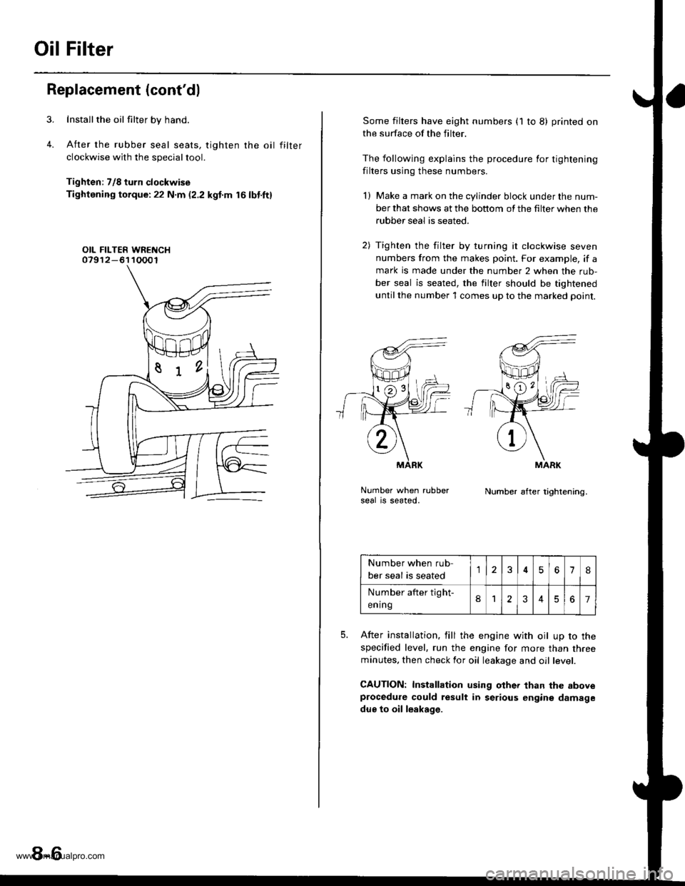
After the rubber seal seats, tighten rhe oil filter
clockwise with the special tool.
Tighten: 7/8 turn clockwise
Tightening torque:22 N.m (2.2 kgt'm 16lbt.ft)
OIL FILTER WRENCH07912-61 10001
8-6
Some filters have eight numbers (1 to 8) printed on
the surface of the filter.
The following explains the procedure for tightening
filters using these numbers.
l) Make a mark on the cylinder block under the num-
ber that shows at the bottom of the filter when the
rubber seal is seated.
2) Tighten the filter by turning it clockwise seven
numbers from the makes point. For example, if a
mark is made under the number 2 when the rub-
ber seal is seated, the filter should be tightened
until the number 1 comes up to the marked point.
Number when rubberseal is seated.Number af ter tightening.
5.After installation. fill the engine with oil up to the
specified level, run the engine for more than threeminutes, then check for oil leakage and oil level.
GAUTION: Installation using other than the aboveprocedure could result in serious engine damage
due to oil leakage.
MARK
Number when rub-
ber seal is seated567IJ
Number after tight-
ening8123467
www.emanualpro.com