Ignition wiring HONDA CR-V 1999 RD1-RD3 / 1.G Workshop Manual
[x] Cancel search | Manufacturer: HONDA, Model Year: 1999, Model line: CR-V, Model: HONDA CR-V 1999 RD1-RD3 / 1.GPages: 1395, PDF Size: 35.62 MB
Page 846 of 1395

Steering
Special Toofs ............. 17-2
Component Locations
Index ................ ....... 17-3
Troubleshooting
General Troubleshooting ................ 1 7-4
Noise and Vibration ......................... 17-8
Fluid Leaks ............. 17-10
Inspection and Adiustment
Steering Operation .......................... 17-12
Power Assist Check
With Vehicle Parked ....................
Steering Linkage and Gearbox .......
Pump Belt
Rack Guide Adjustment ...................
Fluid Rep|acement ...................,,.,....
Pump Pressure Check .................,,...
*Steering Wheel
Removal ................. 17-18
*Steering Column
Removal/lnstallation ................ ....... 17 -2O
lnspection .............. 17-21
Steering Lock Replacement ............ 17 -22
Power Steering Hoses, Lines
Ffuid Leakage Inspection ................. 17 -23
Repfacement .......... 17-23
Power Steering Pump
Repfacement .......... 17-24
Disassembly ...........17-25
fnspection .............. 17-26
Reassembly ............ 17-28
Power Steering Gearbox
Removal ................. 17-31
Disassembly ........... 17-34
Reassembly ............ 17-40
Ball Joint Boot Replacement .......... 17-50
Installation ............. 17-51
17-12
17-13
17-14
l7-15
17-15
17-16
Disassembly/Reassembly............... 17-18
4'%/b.......... -r'-7--a/
SUPPLEN\EN AL RES\RA(N SYSTES{ (SRS\
This model has an SRS which includes a driver's airbag in the steering wheel hub. a passenger's airbag in the dashboardabove the glove box ('97 - 00 models), and seat belt tensioners in the seat belt retractors ('98 - 00 models). Informationnecessary to safely service the SRS is included in this Service Manual. ltems marked with an asterisk (*) on the contentspage include, or are located near, SBS components. Servicing. disassembling or replacing these items will require specialprecautions and tools, and should only be done by an authorized Honda oearer.
To avoid rendering the SRS inoperative, which could lead to peFonal iniury or death in the event of a sevore trontalcollision. allSRS service work must be performod by an authorized Honda dealer.lmproper service procedurgs, including incorrect removal and installalion of the SRS, could lead to personal iniurycaused by unintontional deployment of th€ airbags {'97 - 00 models), and seat belt tensioners ('98 - 00 modelsl.Do not bump the SRS unit. Otherwise, the system may lail in case ot a collision, or the airbags may deploy when theignition switch is ON (lll.
SRS electrical wiring harnesses are identitied by yellow colof coding. Ralated components are located in the steeringcolumn, front console, dashboard, dashboard lower panel, and in the dashboard above the glove box. Do not use elec-trical test equipment on these cilcuits,
www.emanualpro.com
Page 1090 of 1395

a
Heater and Air Conditioning
Heater ...........21
NOTE: Section 21 ("Heater") is included in section 22.
Air Conditioning ......'..'.. '.'22'1
SUPPLEMENTAL RESTRAINT SYSTEM (SRS}
This model has an SRS which includes a driver's airbag in the steering wheel hub, a passenger's airbag in the dashboard
above the glove box ('97,00 models). and seat belt tensioners in the seat belt retractors ('98 - 00 models). Information
necessary to safely service the SRS is included in this Service Manual. ltems marked with an asterisk (*) on the contents
page include. or are located near, SRS components. Servicing, disassembling or replacing these items will require special
precautions and tools, and should only be done by an authorized Honda dealer.
@. To avoid rendering the SRS inoperative, which could lead to personal iniury or death in the event of 8 severe frontal
collision, all SRS service work must be performed by an authotized Honda dealer.
lmproper service procedures, including incorrect removal and installation of the SRS, could lead to personal iniury
caused by unintentional deployment of the airbags ('97 - 00 models), and seat belt tensioners 138 - 00 models).
Do not bump the SRS unit. Otherwise, the system may fail in case of a collision, or the airbags may deploy when the
ignition switch is ON {lll.
SRS eleqtrical wiring harnesses are identified by yellow color coding. Related components are located in the steering
column, front console, dashboard, dashboard lower panel, and in the dashboard above the glove box. Do not use elec-
tricaltest equipment on thes€ cilcuils.
www.emanualpro.com
Page 1317 of 1395

Precautions/Procedures
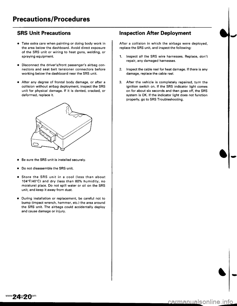
SRS Unit Precautions
Take extra care when painting or doing body work in
the area below the dashboard. Avoid direct exposure
of the SRS unit or wiring to heat guns, welding, or
spraying equipment.
Disconnect the driver's/front passenger's airbag con-
nectors and seat belt tensioner connectors before
working below the dashboard near the SRS unit.
After any degree of frontal body damage, or after a
collision without airbag deployment, inspect the SRS
unit for physical damage. lf it is dented, cracked, or
detormed, reolace it,
Be sure the SRS unit is installed securelv.
Do not disassemble the SRS unit.
Store the SRS unit in a cool {less than about
104"F/40"C) and dry {less than 80o/o humidity. no
moisture) place. Do not spill water or oil on the SRS
unit, and keep it awav from dust.
During installation or replacement, be careful not to
bump (impact wrench, hammer, etc.) the area a[ound
the SRS unit, The airbags could accidentally deploy
and cause damage or injury.
24-20
,..4
Inspection After Deployment
After a collision in which the airbags were deployed.
replace the SRS unit, and inspect the following:
1. Inspect all the SRS wire harnesses. Replace, don't
repair, any damaged harnesses
2. Inspect the cable reel for heat damage, lf there is any
damage. replace the cable reel.
3. After the vehicle is completely repaired, turn the
ignition switch on. lf the SRS indicator light comes
on for about six seconds and then goes off, the SRS
system is OK. lf the indicator light does not function
properly, go to SRS Troubleshooting.
rD
www.emanualpro.com
Page 1385 of 1395

Driver's Airbag
Replacement lcont'd)
CAUTION: 8. sure to instattthe SRS wiring so that it isnot plnched or inlerfsring with other parts.
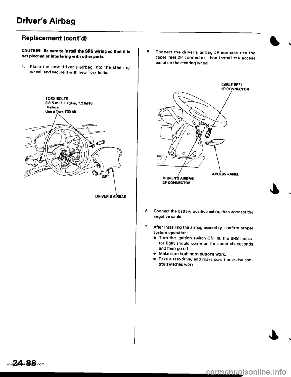
4. Place the new driver's airbag into the steeringwheel, and secure it with new Torx bolts.
TORX EOLTS9.8 N,m 11.0 kgl.m, 7.2 tbf,ftlFeplace.
24-88,
5. Connect the driver's airbsg 2p connector to thecable reel 2P connector, then install the accesspanel on the steering wheel.
Connect the battery positive cable. then connect thenegative cable.
After installing the airbag assembly, confirm proper
system operation:
. Turn the ignition switch ON llt); the SRS indica-tor light should come on for about six secondsand then go off.. Mske sure both horn buttons work.o Take a test-drive, and make sure the cruise con-trol switches work.
7.
2P CONNECTOR
www.emanualpro.com
Page 1387 of 1395

Front Passenger's Airbag
Replacement (cont'd)
GAUTION: Be sure to installthe SRS wiring so that it isnot pinched or interfering with olher parts.
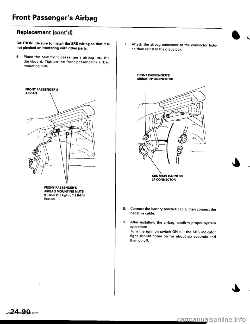
6. Place the new front passenger's airbag into thedashboard. Tighten the front passenger,s airbagmountrng nuts.
FRONT PASSENGER'SAIRBAG MOUNTING NUTS9.8 N.m {1.0 kgJ.m,7.2 lbf ft)Replace.
FRONT PASSENGER'S
24-90
7. Attach the airbag connector to the connector hold_er, then reinstall the glove box.
Connect the b8ttery positive cable, then connect thenegative cable.
After installing the airbag. confirm proper sysremooerauon:
Turn the ignition switch ON ( ); the SRS indicatorlight should come on for about six seconds andthen go off.
FRONT PASSENGER'S
www.emanualpro.com