Normal temperature HONDA CR-V 1999 RD1-RD3 / 1.G Workshop Manual
[x] Cancel search | Manufacturer: HONDA, Model Year: 1999, Model line: CR-V, Model: HONDA CR-V 1999 RD1-RD3 / 1.GPages: 1395, PDF Size: 35.62 MB
Page 123 of 1395
Timing Belt
Removal
Replace the timing belt at 105,000 miles (168,000 km)
according to the maintenance schedule {normal condi-
tions/severe conditions). lf the vehicle is regularly driven
in either of the following conditions, replace the timing
belt at 60,000 miles (U.S.A.l 100.000 km (Canada).
- ln very high temperatures (over 110'F, 43"C).- In very low temperatures (under -20"F. -29"C).
Turn the crankshaft pu\ley so the No. 1 piston is at
top dead center (TDC).
Remove the guard bar and splash shield (see page
5-7 ).
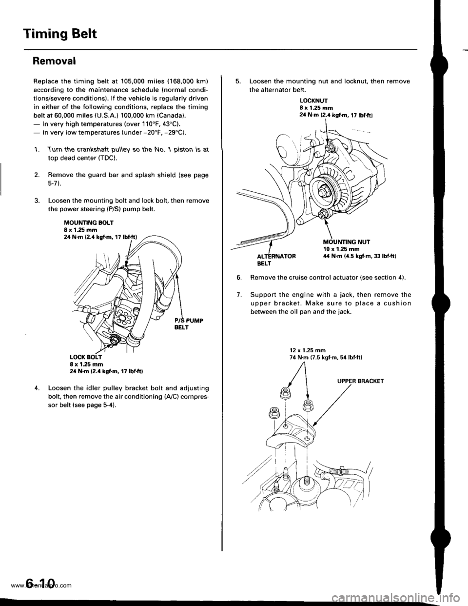
Loosen the mounting bolt and lock bolt. then remove
the power steering (P/S) pump belt.
MOUNNNG BOLT8 x 1.25 rnm
1.
2.
,l
4. Loosen the idler pulley bracket bolt and adjusting
bolt, then remove the air conditioning (lVC) compres
sor belt (see page 5-4).
6-10
24 N.m {2.4 kgt.m, 17 lbf.ftl
24 N.m 12.4 kgf.m, lt lbf.ftl
5. Loosen the mounting nut and locknut, then remove
the altefnator belt.
LOCKNUTI x 1.25 mm2a N.m 12.4 kgt m, 17 lblftl
6.
10 x 1,25 mm4,1 N.m (,1.5 kgt m, 33 lbtftl
Remove the cruise control actuator (see section 4).
Support the engine with a jack, then remove the
upper bracket. Make sure to place a cushion
between the oil Dan and the iack.
12 x 1.25 mm74 N.m (7.5 kgf m, 54 lbtftl
7.
BRACKET
AELT
www.emanualpro.com
Page 138 of 1395
Valve Guides
Valve Movement
1. Measure the guide-to-stem clearance with a dial
indicator while rocking the stem in the direction of
normal thrust (wobble method),
lntake Valve Stem-to-Guide Clearance:
Standard (Newl: 0.04 - 0.10 mm
(0.002 - 0.004 in)
Service Limit 0.16 mm (0.006 in)
Exhaust Valve Stem-to-Guide Clearance:
Standard {Newl: 0.10 - 0.16 mm
(0.004 - 0.006 inl
Service Limit: 0,22 mm (0.009 inl
lf the measurement exceeds the service limit,
recheck using a new valve.
lf the measurement is now within the service limit,
reassemble using a new valve.
lf the measurement still exceeds the limit, subtract the
O.D. of the valve stem, measured with a micrometer,
from the l.D. of the valve guide, measured with an
inside micrometer or ball gauge.
Take the measurements in three places along the
valve stem and three places inside the valve guide
The difference between the largest guide measure-
ment and the smallest stem measurement should
not exceed the service limit.
lntake Valve Stem-to-Guide Clearance:
Standard (New): 0.02 - 0.05 mm
{0.001 - 0.002 in)
Service Limit: 0.08 mm (0.003 in)
Exhaust Valve Stem-to-Guide Clearance:
Standard (New): 0.05 - 0.08 mm
(0.002 - 0.003 in)
Service Limit: 0.11 mm (0.004 in)
2.
3.
Replacement
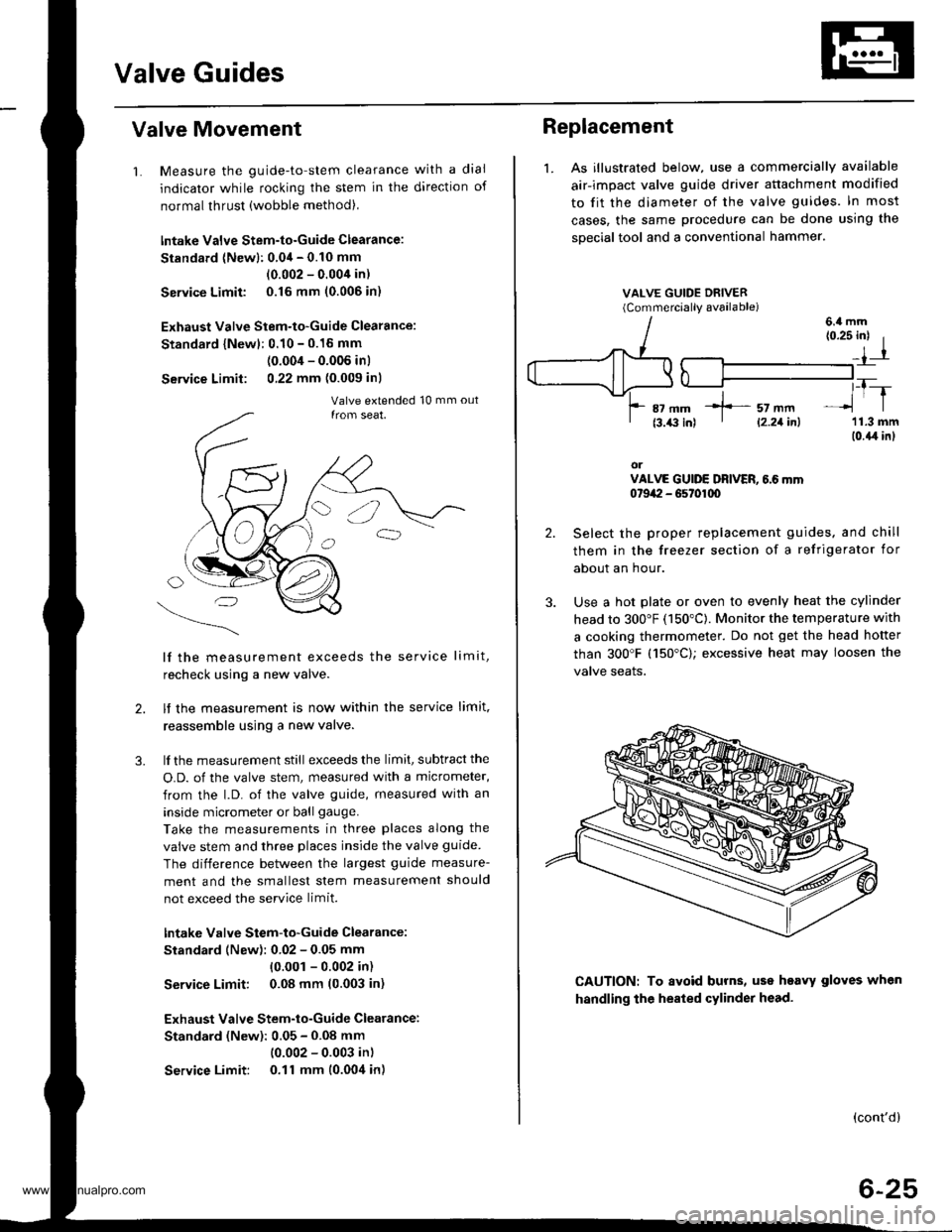
1. As illustrated below, use a commercially available
air-impact valve guide driver attachment modified
to fit the diameter of the valve guides. In most
cases, the same procedure can be done using the
sDecial tool and a conventional hammer.
VALVE GUIDE DRIVER(Commerciallv available)
2.
3.
(0.25 inl I
_,1-r
,_T-_lrl
'11.3 mm(0.{,r in}
orVALVE GUIDE DRIVER, 6.6 mm0t9a:I - G5t01q)
Select the proper replacement guides. and chill
them in the freezer section of a refrigerator for
about an hour.
Use a hot plate or oven to evenly heat the cylinder
head to 300"F (150"C). Monitor the temperature with
a cooking thermometer. Do not get the head hofter
than 300'F (150"C); excessive heat may loosen the
valve seaIs.
6.4 mm
CAUTION: To avoid burns, uss heavy gloves when
handling the heated cylinder head.
(cont'd)
6-25
*]-- sz mm' l2.21inl
www.emanualpro.com
Page 167 of 1395
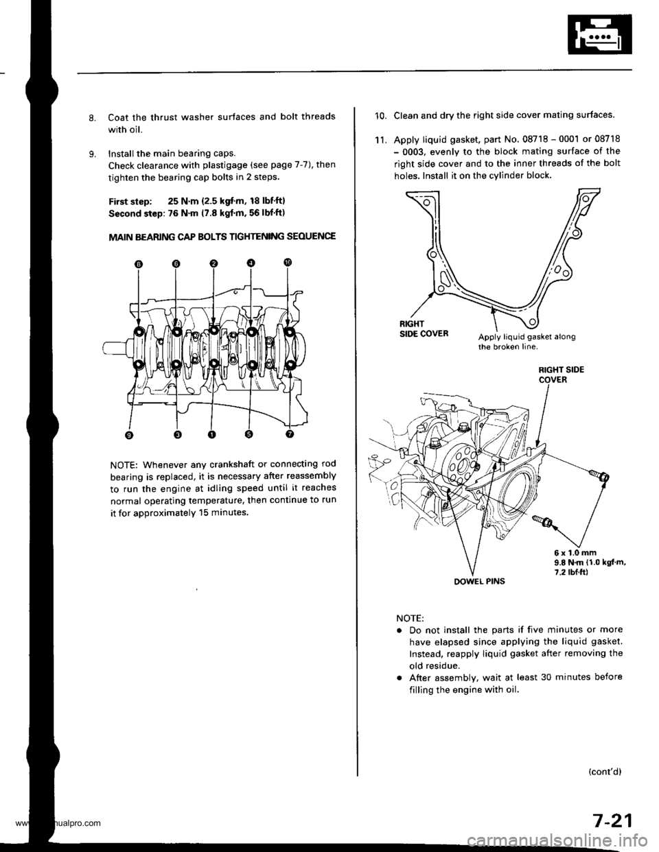
Coat the thrust washer surtaces and bolt threads
with oil.
Installthe main bearing caps.
Check clearance with plastigage (see page 7-7), then
tighten the bearing cap bolts in 2 steps.
First slsp: 25 N.m {2.5 kgf'm, 18 lbf'ft}
Sscond step: 76 N'm (7.8 kgf'm. 56 lbf'ft)
MAIN BEARING CAP BOLTS TIGHTENING SEOUENCE
NOTE: Whenever any crankshaft or connecting rod
bearing is replaced, it is necessary after reassembly
to run the engine at idling speed until it reaches
normal operating temperature, then continue to run
it for approximatelY 15 minutes.
10.Clean and dry the right side cover mating surfaces.
Apply liquid gasket, part No. 08718 - 0001 or 08718
- 0003, evenly to the block mating surface of the
right side cover and to the inner threads of the bolt
holes. Install it on the cylind€r block
11,
6x1.0mm9.E N.m {1.0 kgt m,7.2 tbf.ft)
NOTE:
. Do not install the parts if five minutes or more
have elapsed since applying the liquid gasket.
Instead, reapply liquid gasket after removing the
old residue.
. After assembly, wait at least 30 minutes before
filling the engine with oil.
(cont'dl
7-21
RIGHT SIDE
OOWEL PINS
www.emanualpro.com
Page 283 of 1395

Fuel Cut-off Control
. During deceleration with the throttle valve closed, current to the fuel injectors iscutoffto improvefuel economyat
speeds over 970 rpm ('97 - 98 models), 920 rpm ('99 - 00 modelsl.
. Fuel cut-off action also takes place when engine speed exceeds 6,500 rpm ('97 - 98 models), 6900 rpm ('99 - 00
models), regardless of the position of the throttle valve, to protect the engine from over-rewing.
With Ay'T model. the PCM cuts the fuel at engine speeds over 5,000 rpm when the vehicle is not moving.*'�
4,./C Comoressor Clutch Relav
When the ECM/PCM receives a demand for cooling from the air conditioning system, it delays the compressor from
being energized, and enriches the mixture to assure a smooth transition to the Ay'C mode.
Evaporative Emission (EVAP) Purge Control Solenoid Valve
When the engine coolant temperature is above 154"F (68'C), the ECM/PCM controls the EVAP purge control solenoid
valve which controls vacuum to the EVAP purge control canister,
Alternator Control
The system controls the voltage generated at the alternator in accordance with the electrical load and driving mode.
which reduces the engine load to improve the fuel economy.
PCM Fail-saf e/Back-up Functions
1. Fail-safe Function
When an abnormality occurs in a signal from a sensor, the ECM/PCM ignores that signal and assumes a pre-pre
grammed value for that sensor that allows the engine to continue to run.
2. Back-up Function
When an abnormality occurs in the ECM/PCM itself, the fuel injectors are controlled by a back-up circuit independent
of the system in order to permit minimal driving.
3. Self-diagnosis Function IMalfunction Indicator Lamp (MlL)l
When an abnormality occurs in a signal from a sensor, the ECM/PCM supplies ground for the MIL and stores the DTC
in erasable memory. When the ignition is initially turned on {ll), the ECM/PCM supplies ground for the MIL for two
seconds to check the MIL bulb condition.
4. Two Trio Detection Method
To prevent false indications, the Two Trip Detection Method is used for the HO2S*1, fuel metering-related. idle control
system, ECT sensor and EVAP control system self-diagnostic functions. When an abnormality occurs, the ECM/PCM
stores it in its memory. When the same abnormality recurs after the ignition switch is turned OFF and ON (ll) again,
the ECM/PCM informs the driver by lighting the MlL. However, to ease troubleshooting, this function is cancelled
when you jump the service check connector, The MIL will then blink immediately when an abnormality occurs.
5. Two (or Three) Driving Cycle Detection Method {'97 model)
A "Driving Cycle" consists of starting the engine, beginning closed loop operation, and stopping the engine. lf misfir-
ing that increases emissions or EVAP control system malfunction is detected during two consecutive driving cycles.
or TWC deterioration is detected during three consecutive driving cycles, the ECM/PCM turns the MIL on. However, to
ease troubleshooting, this function is cancelled when you jump the service check connector. The MIL will then blink
immediately when an abnormality occurs.
*1: '97 - 98 models*2: '99 - 00 models
5.
www.emanualpro.com
Page 300 of 1395
PGM-FI System
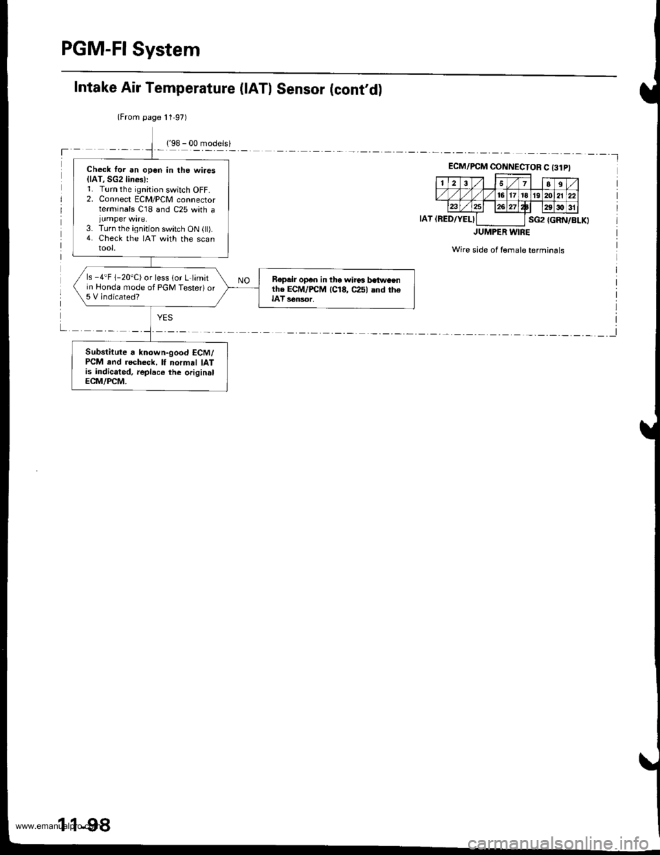
Check for an open in the wires{lAT, SG2lines):1. Turn the ignition switch OFF.2. Connect ECM/PCM connectorterminals C18 and C25 with ajumper wire.3. Turn the ignition switch ON (ll).4. Check the IAT with the scantool.
ls -4'F 1-20"C) or less (or L limitin Honda mode of PGM Testeri or5 V indicated?
Repsir op€n in the wirca batweenthe ECM/PCM 1C18, C25l and theIAT s€nsor.
Substitute a known-good ECM/PCM rnd recheck, lf normal IATis indicated, leplaco the originslECM/PCM.
Intake Air Temperature (lATl Sensor (cont'd)
(From page 11,97)
'l
ECM/PCM CINNECTOR C t3lPl
257II
./ 16171819 202122234 Wp,29c)31
sG2IAT {RED/YELI{GRN/BLK)
JUMPER WIRE
Wire side of fernale terminals
I
1 1-98
www.emanualpro.com
Page 302 of 1395
PGM-FI System
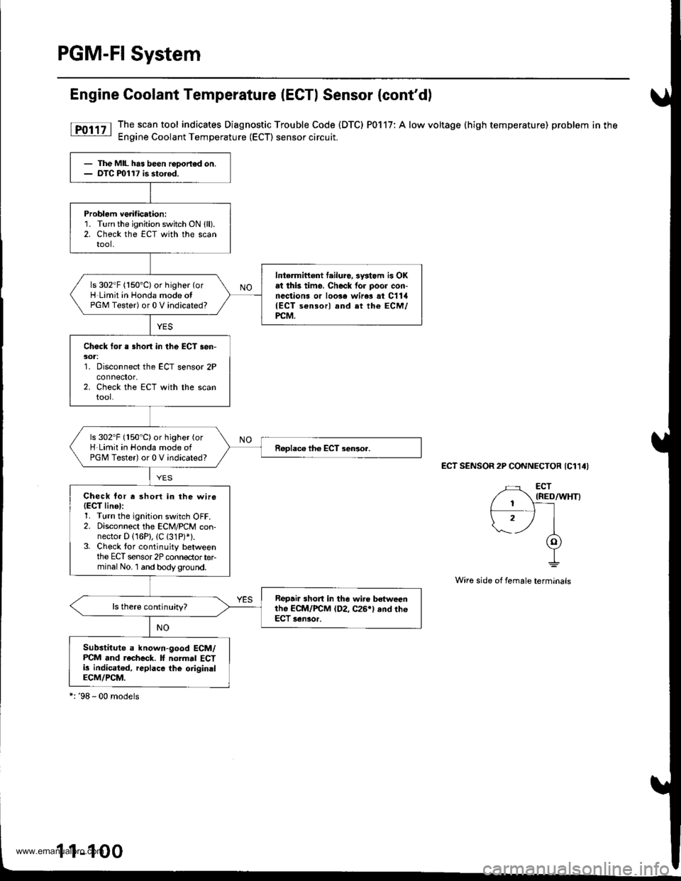
Engine Coolant Temperature (ECTI Sensor {cont'd)
[F011' The.scan tool indicates Diagnostic Trouble Code (DTC) P0117: A low voltage (high temperature) problem in the: Engine Coolant Temperature (ECT) sensor circuit.
ECT SENSOR 2P CONNECTOR {C114I
Wire side of female terminals
- The MIL has been rooortod on.- DTC ml17 is sto.od.
Problem verification:1. Turn the ignition switch ON {ll).2. Check the ECT with the scantool,
Intermittont f.ilure, sysiom is OKat thk time. Check for poor con-nections or loo3e wire3 at C1lil(ECT sensorl and et the ECM/PCM.
ls 302"F (150'C) or higher (or
H Limit in Honda mode otPGM Tester) or 0 V indicated?
Check for a Bhort in the ECT sen-301:'1. Disconnect the ECT sensor 2Pconnefior,2. Check the ECT with the scantool.
ls 302"F (150"C)or higher (or
H-Limit in Honda mode ofPGM Tester) or 0 V indicated?
Check for r shorl in the wirs(EgT linel:1. Turn the ignition switch OFF.2. Disconnect the ECM/PCM con-nector D (16P), (C (31P)*1.3. Check tor continuity betweenthe ECT sensor 2P connectorterminal No. 1 and bodyground.
Repair short in the wir€ betweenthe ECM/FCM (D2, C26rl ,nd th6ECT senaor.
ls there continuity?
Substitute a known-good ECM/PCM and recheck. It normal ECTi! indicatod, replaco the oiiginalECM/PCM.
*:'98 - 00 models
1-1
www.emanualpro.com
Page 304 of 1395
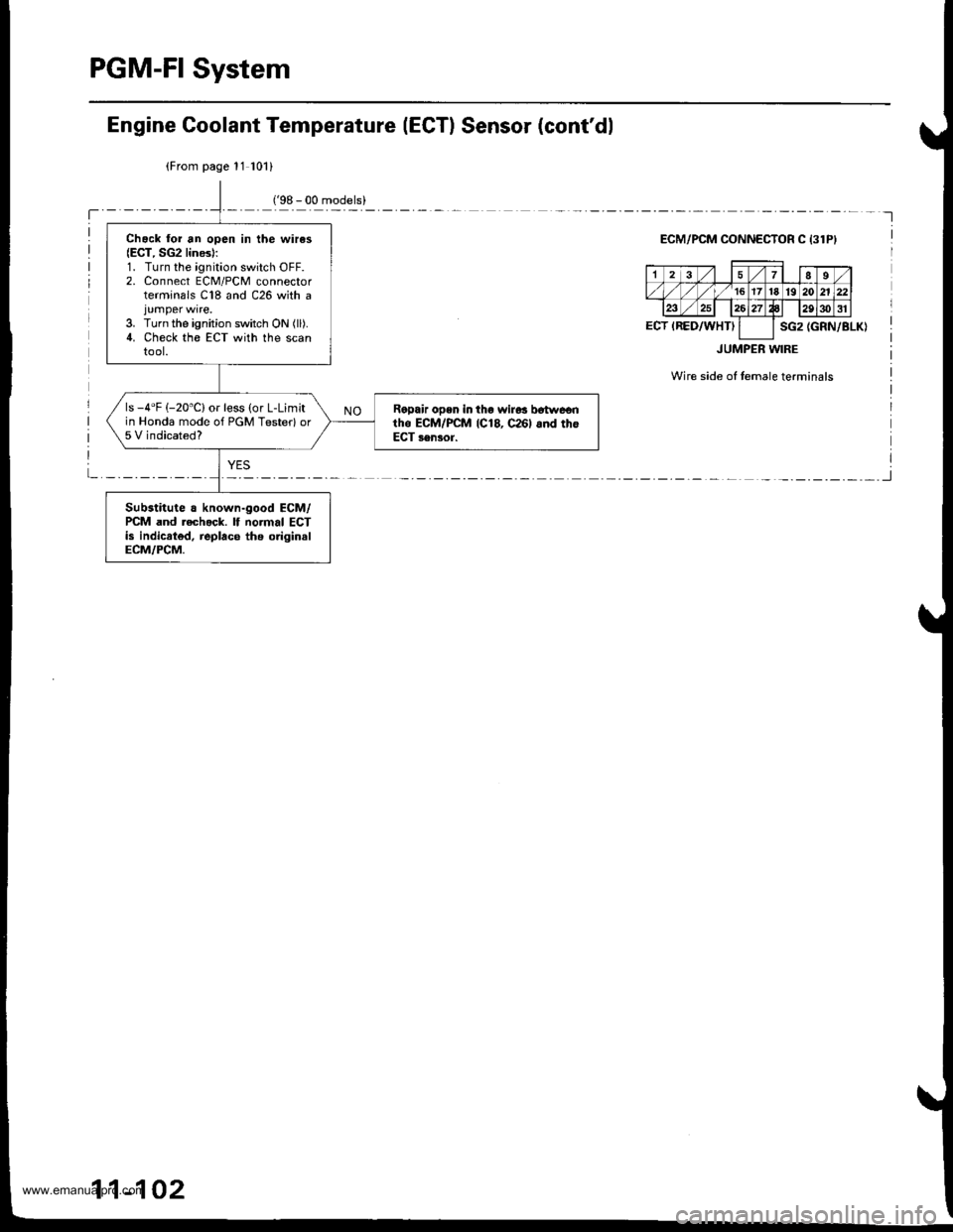
PGM-FI System
Chack lor an open in the wires(ECT, SG2 lines):1. Turn the ignition switch OFF.2. Connect ECM/PCM connectorterminals C18 and C26 with a
3. Turn the ignition switch ON (ll).
4. Check the ECT with the scantool.
ls -4"F (-20"C) or less (or L-Limitin Honda mode of PGM Testerlor5 V indicated?
Ralpair open in tho wir6s b6twe€ntho ECM/PCM 1C18, c26l 6nd thoECT sensor.
Substitute a known-good ECM/PCM and rech.ck. lf normal ECTis indicrted, replace ths originslECM/PCM.
Engine Goolant Temperature (ECTI Sensor (cont'dl
(From page 11 101)
ECM/PCM OONNECTOR C 13lPI
(GRN/BLK)
JUMPER WIRE
Wire side of temale terminals
17I9
,/ 1617't8'1920n
ECT IRED/WHTIsG2
11-102
www.emanualpro.com
Page 504 of 1395
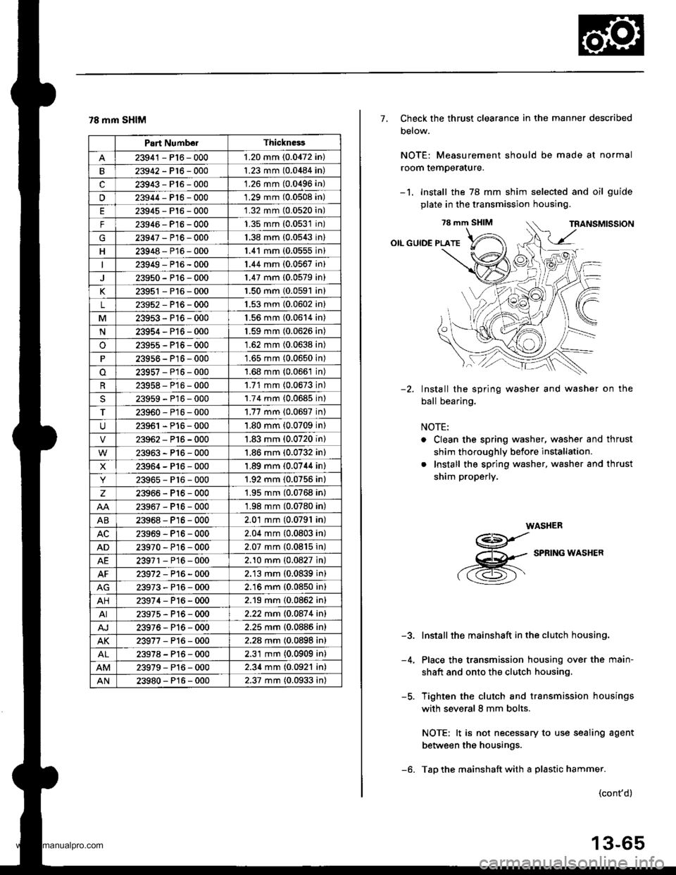
78 mm SHIM
Part NumborThickness
23941 - P16 - 0001.20 mm (0.0472 in)
23942-P16-0001.23 mm (0.0484 in)
c23943-P16-000'1.26 mm (0.0496 in)
u23944-Pt6-0001.29 mm (0.0508 in)
23945-P16-0001.32 mm (0.0520n)
F23946- P16 - 0001.35 mm (0.0531n)
G23947-P16-0001.38 mm {0.0543n)
H23948-P16-0001.41 mm (0.0555n)
23949-P16-0001.44 mm (0.0567 in)
23950-P16-0001.47 mm (0.0579 in)
K23951 - P16 - 0001.50 mm {0.0591 in}
L23952-Pl6-0001.53 mm (0.0602 in)
M23953-P16-0001.56 mm (0.0614 in)
N23954-P16-0001.59 mm (0.0626 in)
o23955-P15-0001.62 mm (0.0638 in)
23956 - P16 - 0001.65 mm (0.0650 in)
23957-P16-0001.68 mm (0.066't in)
23958- P16 - 0001.71 mm (0.0673 in)
23959-P16-0001.74 mm {0.0685 in)
T23960-P16-0001.77 mm {0.0697 inl
23961 - P16 - 0001.80 mm (0.0709 in)
23962-P16-0001.83 mm (0.0720 in)
23963-P16-000'1.86 mm (0.0732 in)
X23964-P16-0001.89 mm (0.0744 in)
23965-P16-0001.92 mm (0.0756 in)
z23966-Pl6-0001.95 mm (0.0768 in)
23967-Pl6-0001.98 mm (0.0780 in)
AB23968-P16-0002.01 mm (0.0791 in)
23969-Pl6-0002.04 mm (0.0803 in)
AD23970 - Pl6-0002.07 mm {0.0815 in)
AE23971 - P16 - 0002.10 mm {0.0827 in}
23972-P16-0002.13 mm (0.0839 in)
23973-P16-0002.16 mm (0.0850 in)
AH23974-P16-0002.19 mm (0.0862 in)
AI23975-P16-0002.22 mm 10.087 4 inl
AJ23976-Pl6-0002.25 mm {0.0886 in}
AK23977-P16-0002.28 mm {0.0898 in)
23978-Pl6-0002.31 mm (0.0909 in)
23979-Pl6-0002.34 mm (0.0921 in)
AN23980-P16-0002.37 mm (0.0933 in)
7, Check the thrust clearance in the manner described
Delow.
NOTE: Measurement should be made at normal
room temperature.
-1. Install the 78 mm shim selected and oil guide
plate in the transmission housing.
78 mm SHIM
OIL GUIDE PLATE
Install the spring washer and washer on the
ball bearing.
NOTE:
. Clean the spring washer, washer and thrust
shim thoroughly before installation.
. Install the spring washer, washer and thrust
shim properly.
WASHER
g
,-g
SPRTNG*ASHER
Install the mainshaft in the clutch housing.
Place the transmission housing over the main-
shaft and onto the clutch housing.
Tighten the clutch and transmission housings
with several 8 mm bolts.
NOTE: lt is not necessary to use sealing agent
between the housings.
Tap the mainshaft with a plastic hammer.
-2.
-5.
(cont'd)
13-65
www.emanualpro.com
Page 534 of 1395
Description
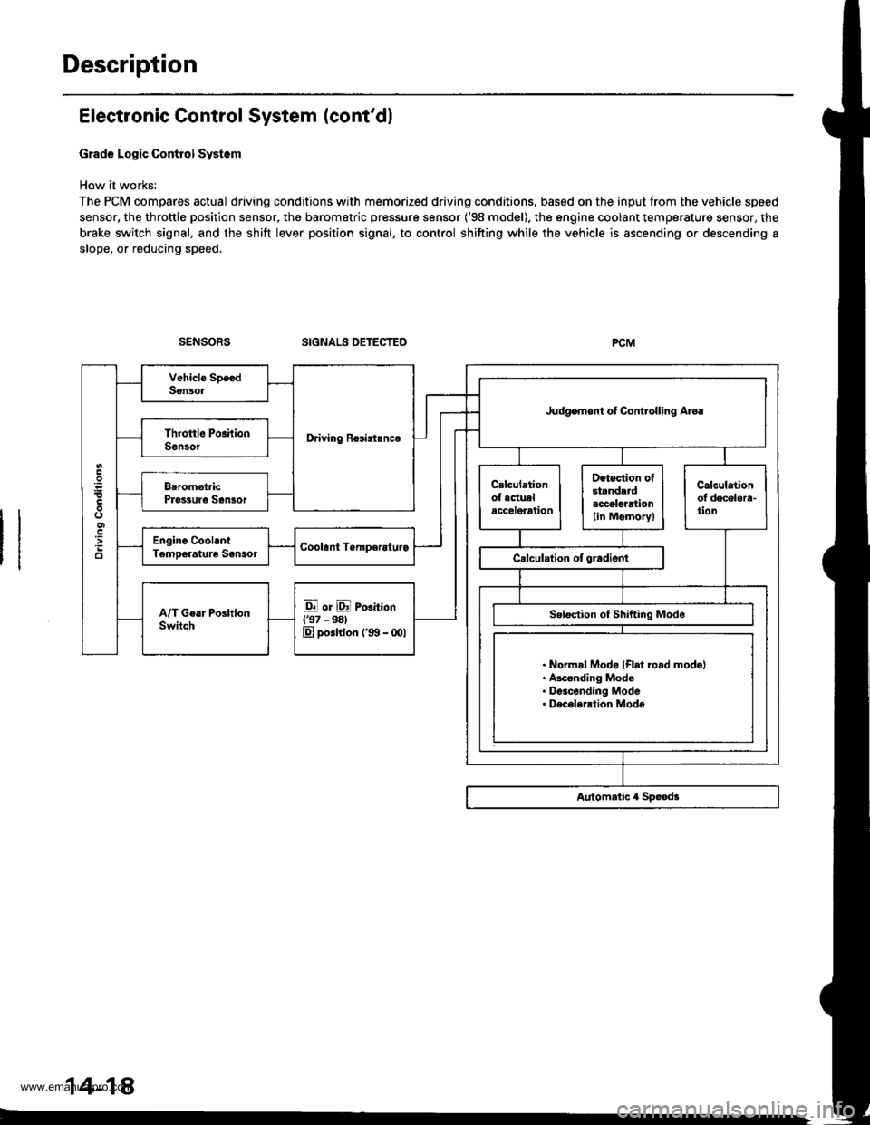
Electronic Control System (cont'dl
Grade Logic Control System
How it works:
The PCM compares actual driving conditions with memorized driving conditions, based on the input from the vehicle speed
sensor, the throttle position sensor, the barometric pressure sensor ('98 model). the engine coolant temperature sensor, the
brake switch signal, and the shift lever position signal, to control shifting while the vehicle is ascending or descending a
slope, or reducing speed.
SIGNALS DETECTED
Driving Rcsisl.nce
Judgemont ot Controlling Aroa
. Normal Modo {Flrt ro.d mode}. Ascending Mode. Deacending Mode. Deceleration Mode
14-14
www.emanualpro.com
Page 673 of 1395
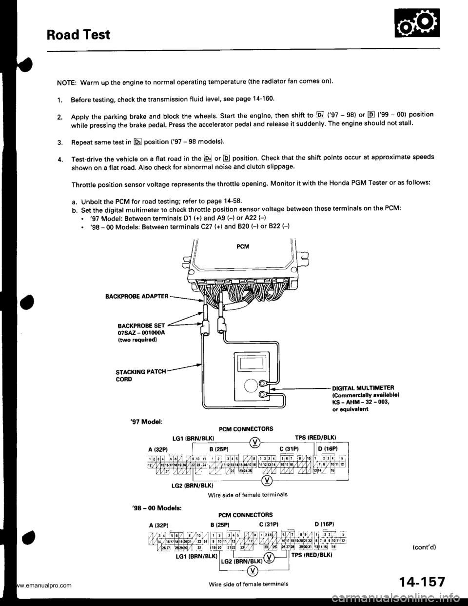
Road Test
NOTE: Warm up the engine to normal operating temperature (the radiator tan comes on).
1. Before testing, check the transmission fluid level, see page 14-160.
2. Apply the parking brake and block the wheels. start the engine, then shift to E {'97 - 98) or E {'gg - 00) position
while pressing the brake pedal. Press the accelerator pedal and release it suddenly. The engine should not stall.
3. Repeat same test in E position ('97 - 98 models).
4. Test-drive the vehicle on a flat road in the E or E position. Check that the shift points occur at approximate speeds
shown on a flat road. Also check for abnormal noise and clutch slippage.
Throttle position sensor voltage represents the throttle opening. Monitor it with the Honda PGM Tester or as follows:
a. Unbolt the PCM for road testing; reJer to page 14-58.
b. Set the digital multimeter to check throttle position sensor voltage between these terminals on the PCM:
. '97 Model: Between terminals D'! (+) and A9 (-) or A22 {-}
. '98 - OO Models; Between terminals C27 (+) and 820 (-) or 822 {-)
BACKPROBE ADAPTER
BACKPROBE SETorsAz - 001moA(two roquircdl
STACKING PATCH
CORD
DIGiTAL MULTIMETER
{Comm€rcirllY .vailablc}KS-AHM-32-003,or equival.nt
'97 Model:PCM CONNECTORS
'98 - 0O Models:
A l32Pt
Wire side of female terminals
PCM CONNECTORS
B {25Pt c l31P}
(cont'd)
LGl (BRN/BLK)
'. //B 1 l'o ti , jl. to a 2r / / 11111t1.t nait la t1 t213tr / t6t, tl / / / / 1 3 / 10n v
t-'a:IM-&E -Llfiffi-fl)\"".'E
Wire side ot female termanals14-157
www.emanualpro.com