Radiator cooling fan HONDA CR-V 1999 RD1-RD3 / 1.G Workshop Manual
[x] Cancel search | Manufacturer: HONDA, Model Year: 1999, Model line: CR-V, Model: HONDA CR-V 1999 RD1-RD3 / 1.GPages: 1395, PDF Size: 35.62 MB
Page 29 of 1395
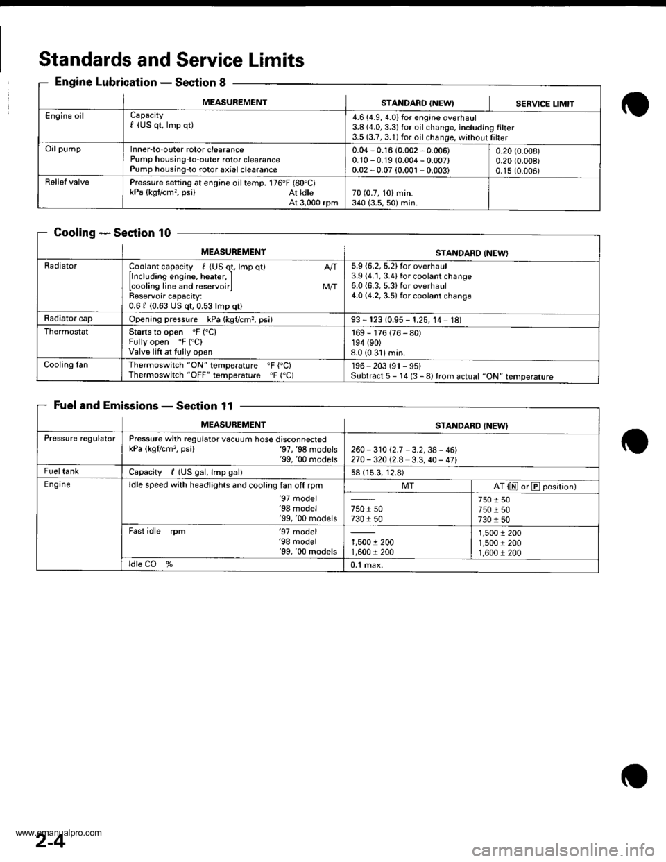
Standards andService Limits
Engine LubricationSection 8
CoolingSection 10
Fuel and EmissionsSection 11
MEASUREMENTSTANDARO {NEWISERVICE LIMIT
Engine oilCapacityf (US qt, lmp qt)4.6 (4.9, 4.0)Ior engine overhaul3.8 {4.0,3.3)for oilchange, including filter3.5 (3.7, 3.1) for oil change, without Iilter
OilpumpInner-to-outer rotor clearancePump housing-to-outer rotor clearancePump housing-to rotor axial clearance
0.04 - 0.16 (0.002 - 0.006)0.10 -0.19 (0.004 - 0.007)0.02 -0.07 (0.001 - 0.003i
0.20 (0.008)
0.20 (0.008)
0.15 (0.006)
Relief valvePressure setting at engine oil temp. 176'F (80'C)kPa (kgt/cm,, psi) At ldleAt 3,000 rpm70 (0.7, 10) min.340 {3.5,50) min.
MEASUREMENTSTANDARO INEW}
RadiatorCoolant capacity , (US q1, lmp qt)
llncluding engine, heater, ILcooling line and reservoirlReservoir capacity:0.61 (0.63 US qt,0.53lmp qt)
M/T
5.9 {6.2, 5.2}tor overhaul3.9 (4.1, 3.4ifor coolant change6.0 (6.3, 5.3ifor overhaul4.0 (4.2, 3.5) for coolant change
Radiator capOpening pressure kPa (kgf/cm?, psi)93 - 123 (0.95 - 1.25, 14 18)
ThermostatStarts to open 'F 1"C)Fully open 'F ("C)
Valve lift at tully open
169 - 176 (76 - 80)194 (90)
8.0 (0.31imin.
Cooling fanThermoswitch "ON" temperature "F {'C)Thermoswitch "OFF" temperature 'F ('C)196 - 203 (91 - 95)Subtract 5 - 14 (3 - 8) trom actual "ON" temperature
MEASUREMENTSTANDARD INEW}
Pressure regulatorPressure with regulator vacuum hose disconnectedkPa (kgflcm'�, psi) '97,'98 models'99, '00 rnodels260 - 31012.7 3.2,38- 46)270 -32012.8 3.3,40 - 471
FueltankCapacity / (US gal, lmp gal)58 (15.3, 12.8)
E ngineldle speed with headlights and cooling fan off rpm'97 model'98 model'99, '00 models
MTAT {E or E position)
750 r 50730 1 50
750 t 50750 r 507301 50
Fast idle rpm '97 model'98 model'99, '00 models1,5001 2001,600 r 200
1,5001 2001,5001 2001,600 r 200
ldle CO %0.1 max.
2-4
www.emanualpro.com
Page 189 of 1395
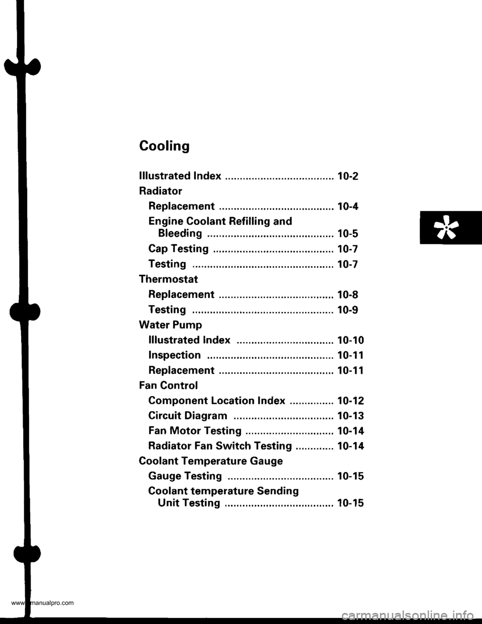
Cooling
f ffustrated Index ........... ..... 1O-2
Radiator
Rep|acement ...........,....,...................... 10-4
Engine Coolant Refilling and
Bleeding ..,.,................. 10-5
Cap Testing .................... 10-7
Testing ......10-7
Thermostat
Rep|acement ....................................... 10-8
Testing ...... 10-9
Water Pump
lllustrated lndex ....,..... .. 10-10
Inspection . 10-1 1
Replacement ....................................,.. 10-1 1
Fan Gontrol
Component Location Index ............... 10-12
Circuit Diagram ............. 10-13
Fan Motor Testing ......... 10-14
Radiator Fan Switch Testing ............. 10-14
Coolant Temperature Gauge
Gauge Testing ............... 10-15
Coolant temperature Sending
Unit Testing ........,....... 10-15
www.emanualpro.com
Page 190 of 1395
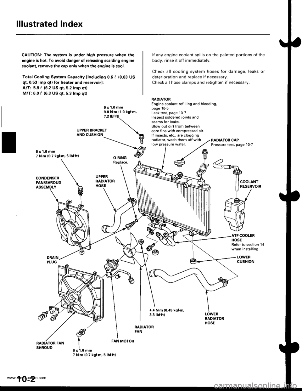
lllustrated Index
CAUTION: The system is under high pressure when the
engine is hot. To avoid danger ol releasing scalding engine
coolant, remove the cap only when the engine is cool.
Total Cooling System Capacity fincluding 0.6 I (0.63 US
qt, 0.53 lmp qt) for heater and reservoirl:
A/T: 5.9 { {6.2 US qt, 5.2 lmp qt)
M/T: 6.0 f (6.3 US $, 5.3 lmp qt)
deterioration and replace if necessar,.
Check all hose clamps and retighten if necessary.
lf any engine coolant spills on the
body, rinse it off immediately.
Check all cooling system hoses
painted portions of the
for damage, leaks or
6x1.0mm9.8 N.m 11.0 kgf.m.1.2 tbl.ftl
RADIATOREngine coolant refilling and bleeding,page 10-5Leak test, page 10 7Inspect soldered joints andseams for leaks.Blow out din from betweencore fins with compressed air.lf insects, etc., are cloggingradiator, wash them off withlow pressure water.RADIATOR CAPPressure test, page 10-7
ATF COOLERHOSEReler to section 14when installing.
LOWERcusHroN
6x1.0mm7 N.m (0.7 kgf.m, 5 lbf ftl
FAN MOTOR
10-2
www.emanualpro.com
Page 194 of 1395
Radiator
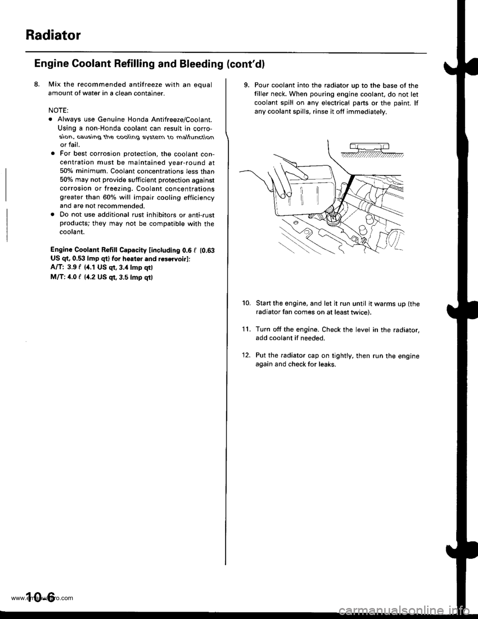
Engine Coolant Refilling and Bleeding (cont'dl
Mix the recommended antifreeze with an equal
amount of water in a clean container.
NOTE:
. Always use Genuine Honda Antifreeze/Coolant.
Using a non-Honda coolant can result in corro-s\on, ca
sng t\e coo\
g sys\em \o ma\lunct\on
o. fail.
For best corrosion protection, the coolant con-
centration must be maintained year-round at50% minimum. Coolant concentrations less than
50% may not provide sufficient protection against
corrosion or freezing. Coolant concentrationsgreater than 60% will impair cooling efficiency
and are not recommended.
Do not use additional rust inhibitors or anti-rustproducts; they may not be compatible with the
coolant.
Engine Coolant Refill Capacity Iincluding 0.6 / 10.63US $, 0.53 lmp qtl for hoater and ressrvoirl:
A/T: 3.9 f {4.1 US $, 3.4 lmp qtl
M/T: 1.O t 14.2 US $, 3.5 lmp qrl
10-6
9. Pour coolant into the radiator uD to the base of the
filler neck. When pouring engine coolant. do not let
coolant spill on any electrical pans or the paint. lf
any coolant spills, rinse it oft immediately.
Start the engine, and let it run until it warms up (the
radiator fan comes on at least twice).
Turn off the engine. Check the level in the radiator,
add coolant if needed.
Put the radiator cap on tightly. then run the engine
again and check for leaks.
11.
10.
12.
www.emanualpro.com
Page 202 of 1395
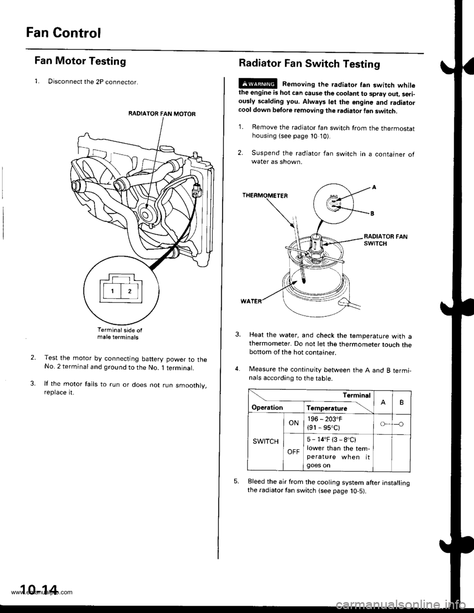
Fan Control
Fan Motor Testing
1. Disconnect the 2P connector.
Terminalside ofmale terminals
Test the motor by connecting battery power to theNo. 2 terminal and ground to the No. 1 terminal.
lf the motor fails to run or does not run smoothly,reptace rt.
RADIATOR FAN MOTOR
10-14
Radiator Fan Switch Testing
E@ Removing the radiator fan switch whilethe engine is hot can cause the coolant to spray out, seri-ously scalding you. Always let the enginc and radiatorcool down before removing the radiator fan switch.
1. Remove the radiator fan switch from the thermostathousing (see page 10 '10).
2. Suspend the radiator fan switch in a container ofwater as shown.
Heat the water, and check the temperature with athermometer. Do not let the thermometer touch thebottom of the hot container.
Measure the continuity between the A and B termi-nals according to the table.
Bleed the air from the cooling system after installingthe radiator fan switch (see page 10-5).
Terminal
op".*i- Tr"ip".a*" \.B
SWITCH
ON196 - 203"F
{91 - 95.C)o---o
OFF
5 - 14"F (3 - 8.C)
lower than the tem-peratu re wh en itgoes on
www.emanualpro.com
Page 301 of 1395
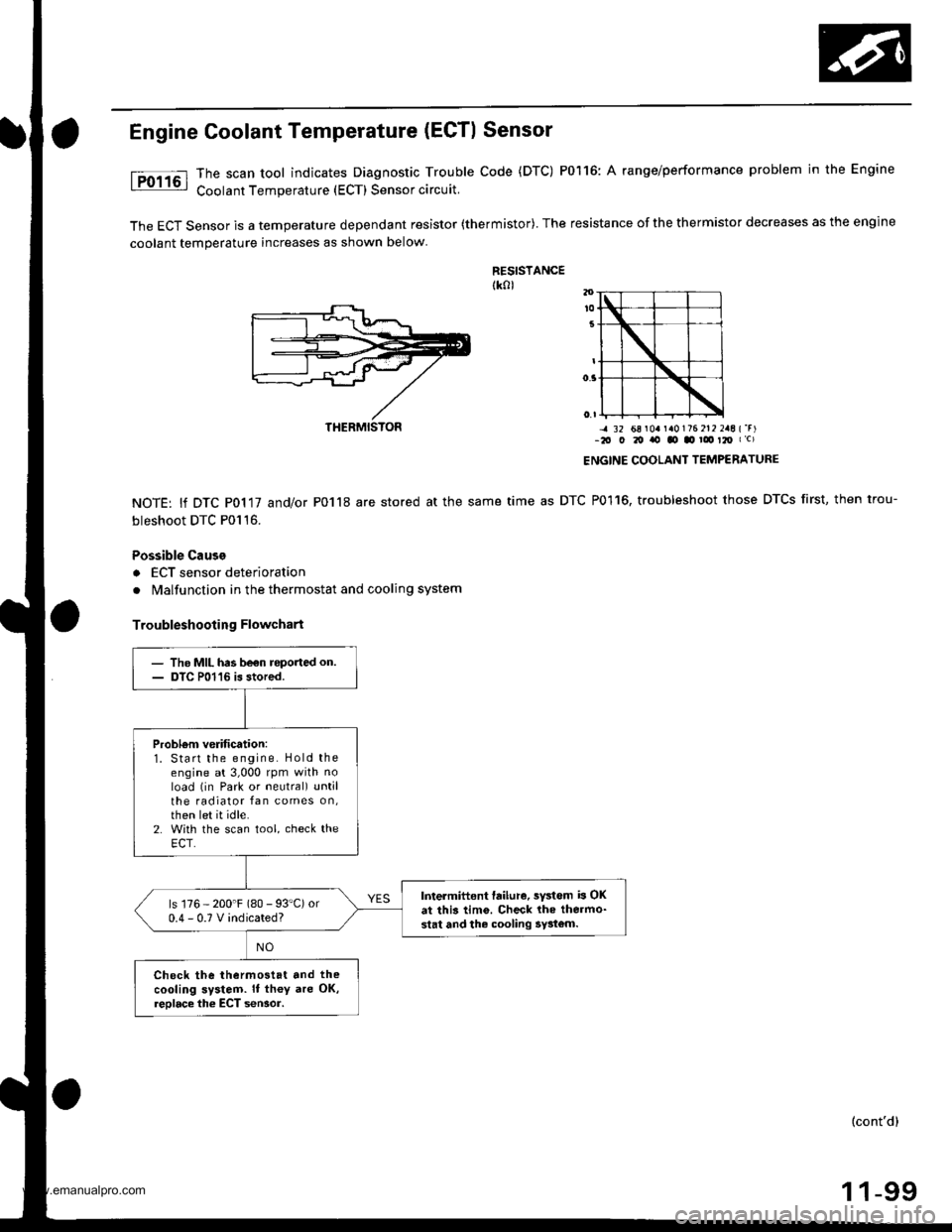
Engine Goolant Temperature (ECTI Sensor
The scan tool indicates Diagnostic Trouble Code (DTC) P0116: A range/performance problem in the Engine
Coolant Temperature (ECT) Sensor circuit.
The ECT Sensor is a temperature dependant resistor (thermistor). The resistance of the thermistor decreases as the engine
coolant temperature increases as shown below
RESISTANCEtk0l
NOTE: lf DTC P0117 and/or P0118 are stored at the same
bleshoot DTC P0116.
Possible Cause
a ECT sensor deterioration
. Malfunction in the thermostat and cooling system
Troubleshooting Flowchart
-4 32 68 r0a r a0176 212 2aE {'r)-2O O 20 ito tO .o ! t2O I c)
ENGINE COOLANT TEMPERATURE
time as DTC P0116, troubleshoot those DTCS first, then trou-
THERMISTON
- The MIL has be€n roported on.- DTC P01'16 is stored.
Probl6m verification:1. Start the engine. Hold theengine at 3,000 rpm with noload (in Park or neutral) untilthe radiator fan comes on,then let it idle.2. With the scan tool, check theECT.
Intermittent failure, sYstem b OKat this tim6. Check lhe thermo-stat and the cooling 5y3tom.
ls 176 - 200'F (80 - 93"C) or0.4-0.TVindicated?
Check the thermostat and the
cooling system. It th€y are OK,reolace the ECT seNor.
(cont'd)
1 1-99
www.emanualpro.com
Page 370 of 1395
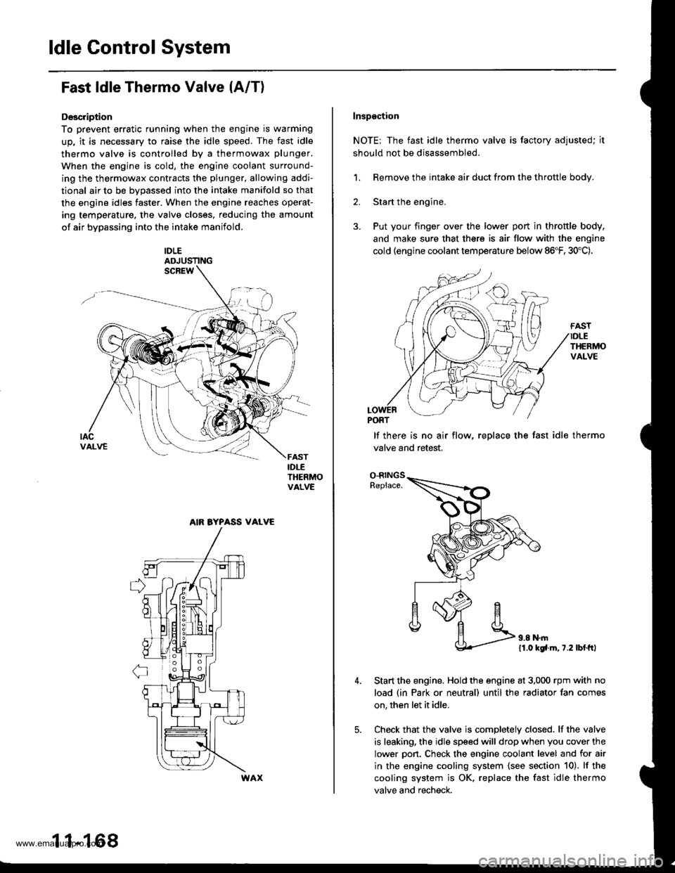
ldle Control System
Fast ldle Thermo Valve lA/T)
Description
To prevent erratic running when the engine is warming
up, it is necessary to raise the idle speed. The fast idle
thermo valve is controlled by a thermowax plunger.
When the engine is cold, the engine coolant surround-
ing the thermowax contracts the plunger, allowing addi-
tional air to be bvDassed into the intake manifold so that
the engine idles faster. When the engine reaches operat-
ing temperature. the valve closes, reducing the amount
of air bypassing into the intake manifold.
IDLEADJUSTING
IDLETHERMOVALVE
AIR BYPASS VALVE
11-168
Inspgction
NOTE: The fast idle thermo valve is factory adjusted; it
should not be disassembled.
1. Remove the intake air duct from the throttle body.
2. Start the engine,
3. Put your finger over the lower port in throttle body,
and make sure that there is air flow with the engine
cold (engine coolant temperature below 86"F, 30'C).
lf there is no air flow, replace the fast idle thermo
valve and retest,
O-RINGSReplace.
11.0 kgfl.m, 7.2 lbl.ftl
Start the engine. Hold the engine at 3,000 rpm with no
load (in Park or neutral) until the radiator fan comes
on, then let it idle.
Check that the valve is completely closed. lf the valve
is leaking, the idle speed will drop when you cover the
lower pon. Check the engine coolant level and for air
in the engine cooling system {see section 10). lf the
cooling system is OK, replace the fast idle thermo
valve and recheck.
www.emanualpro.com
Page 401 of 1395
Emission Control System
System Description
The emission control system includes, a Three Way
Catalytic Converter {TWC), Positive Crankcase Ventilation
(PCV) svstem and Evaporative Emission (€VAP) Control
system. The emission control system is designed to meet
federal and state emission standards.
Tailpipe Emission
Inspsction
!@ Do not smoke during this procsdura. Keep
any open tlame away from your work area.
1. Start the engine. Hold the engine at 3,000 rpm with
no load (in Park or neutral) until the radiator fan
comes on, then let it idle,
Connect a tachometer.
Check and, if necessary, adjust the idle speed, (see
page 11-169, 170).
Warm up and calibrate the CO meter according to the
meter manufacturer's instructions.
Check idle CO with the headlights, heater blower, rear
window defogger, cooling fan, and air conditioner off.
(Canada) Pull the parking brake lever up. Start the
engine, then check that the headlights are off.
CO meter should indicate 0.1% maximum.
4.
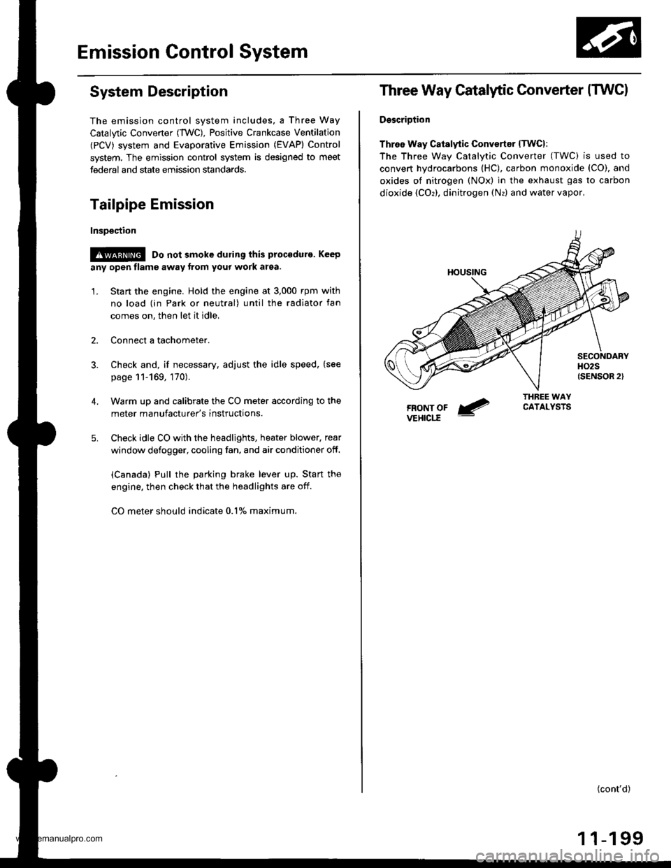
Three Way Catalytic Converter (TWCI
DsscriDtion
Three Way Catalytic Convertsr lTwcl:
The Three wav Catalvtic Converter (TWC) is used to
convert hydrocarbons (HC), carbon monoxide (CO), and
oxides of nitrogen (NOx) in the exhaust gas to carbon
dioxide (COr), dinitrogen (Nr) and water vapor,
{cont'd)
1 1-199
www.emanualpro.com
Page 675 of 1395
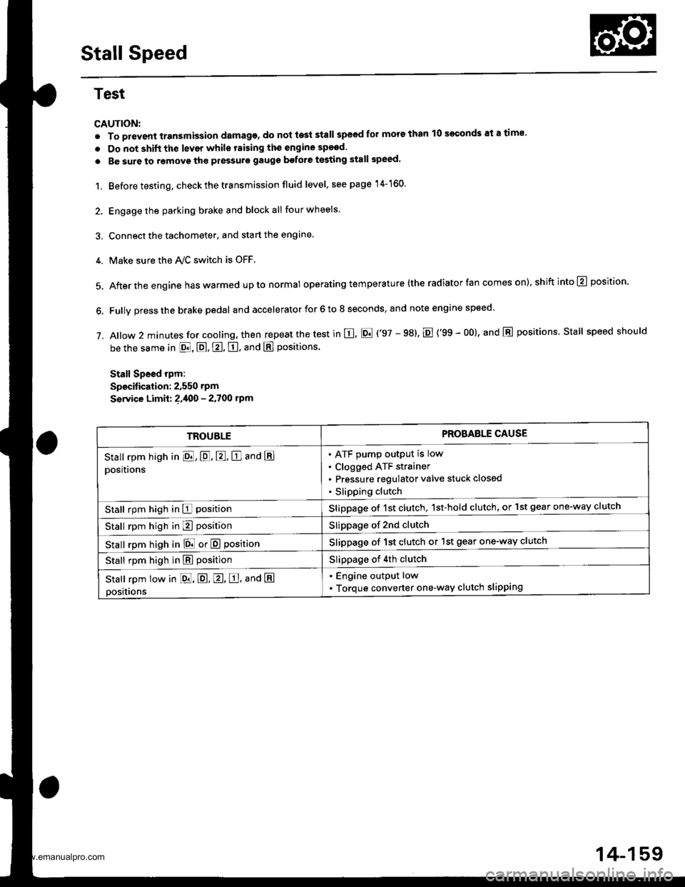
Stall Speed
Test
CAUTION:
. To prevent transmission damage, do not te3t stall speed for mors than 10 s€€onds at a time'
. Do not shift the lever while raising th€ engine spsed.
. Be sure to remove tho pressuro gauge bofore testing stall speed,
1. Before testing, check the transmission fluid level, s€e page 14-160.
2. Engage the parking brake and block all four wheels
3. Connect the tachometer, and start the engane.
4. Make sure the Ay'C switch is OFF
5. After the engine haswarmed upto normal operating temperature (the radiator fan comes on),shiftinto@ position.
6. Fully press the brake pedal and accelerator for 6 to 8 seconds, and note engine speed '
j. A|ow 2 minutes for cooling, then repeat the test in E, E ('97 - 98). E {'99 - 00}, and E positions. Stall speed should
be the same in E, E, E, tr. and E positions
Stall Speed rpm:
Specitication: 2,550 rpm
S€rvice Limit: ?,400 - 2.700 rpm
TROUBLEPROBAELE CAUSE
Stall rpm high in El, E, E, E and E
positions
ATF pump output is low
Clogged ATF strainer
Pressure regulator valve stuck closed
Slipping clutch
Stall rpm high in E positionSlippage of 1st clutch, 1st-hold clutch, or 1st gear one-way clutch
Stall rpm high in E positionSlippage of 2nd clutch
stall rpm high in E! or E positionSlippage of 1st clutch or 1st gear one-way clutch
Stall rpm high in E positionSlippage of 4th clutch
Stall rpm low in [dd, E. E, E, ana E
positions
. Engine output low
. Torque converter one-way clutch slipping
14-159
www.emanualpro.com
Page 1100 of 1395
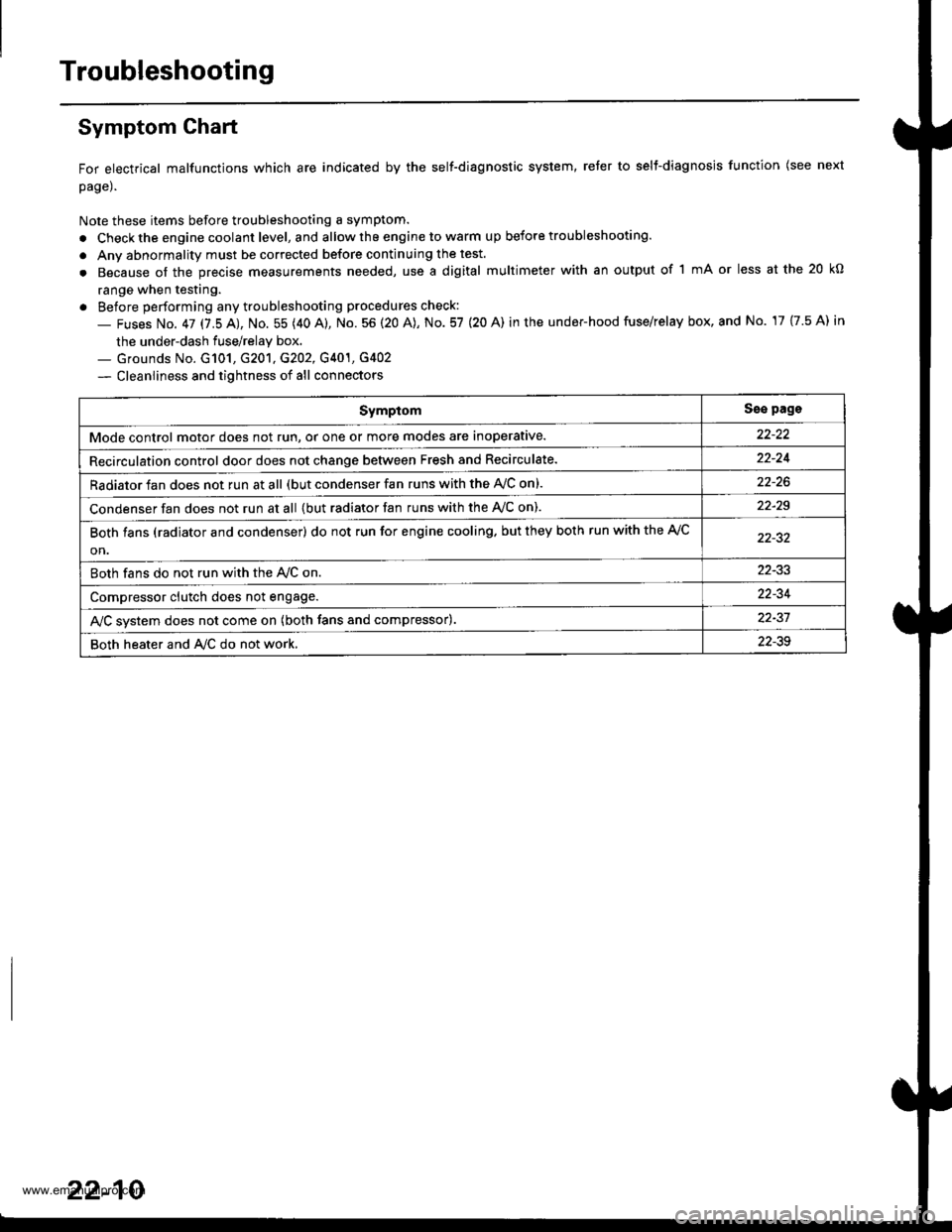
Troubleshooting
Symptom Ghart
For electrical malfunctions which are indicated by the self-diagnostic system, reter to selt-diagnosjs function (see next
page).
Note these items before troubleshooting a symptom.
. Check the engine coolant level, and allow the engine to warm up before troubleshooting.
. Anv abnormality must be corrected before continuing the test.
. Because of the precise measurements needed, use a digital multimeter with an output of 1 mA or less at the 20 kO
range when testing.
. Before performing any troubleshooting procedures check:
- Fuses No. 47 17.5 AJ, No. 55 (40 A), No. 56 (20 A), No. 57 (20 A) in the under-hood fuse/relay box, and No. 17 {7.5 A) in
the under-dash fuse/relay box.._ Grounds No. G101, G201, G202, G401, G4O2
- Cleanliness and tightness of all connectors
SymptomSse pags
Mode control motor does not run, or one or more modes are inoperative.
Recirculation control door does not change between Fresh and Recirculate.22-24
Radiator fan does not run at all (but condenser fan runs with the AVC on).
Condenser fan does not run at all {but radiator fan runs with the Ay'C on).22-29
Both fans (radiator and condenser) do not run for engine cooling. but they both run with the A,/C
on.
Both fans do not run with the Ay'C on22-33
Compressor clutch does not engage.22-34
AJC svstem does not come on (both fans and compressor).22-37
Both heater and A/C do not work,22-39
22-10
www.emanualpro.com