Throttle body HONDA CR-V 1999 RD1-RD3 / 1.G Workshop Manual
[x] Cancel search | Manufacturer: HONDA, Model Year: 1999, Model line: CR-V, Model: HONDA CR-V 1999 RD1-RD3 / 1.GPages: 1395, PDF Size: 35.62 MB
Page 204 of 1395

Fuel and Emissions
Special Tools ...................... 11-2
Component Locations
lndex ...................... ....,.... 11-3
Svstem Description
Vacuum Connections ...........,....,.,................. 1 1-9
Electrical Connections ................................... 1 1-15
System Connectors .,.,,.,............................,.,. 1 1-36
Troubleshooting
Troubleshooting Procedures,.,..................... 11-60
Engine Control Module/Powertrain ConttolModule Terminal Arrangement .............., 11-67
Diagnostic Trouble Code Chart .................... 1 t-75
How to Read Flowcharts .......,.....,.,............... I 1-79
PGM-Fl System
System Description .................,.,.,,,............... 1 1-80
Troubleshooting Flowcharts
Engine Control Module/PowertrainControl Module ........11-52
Manifold Absolute Pressure Sensor ............. 11-90
Intake Air Temperature Sensor .................... 1 1-95
Engine Coolant Temperature Sensor .,..,.,.... 1 1-99
Throttle Position Sensor ...........,.....,.,.,..,...... I 1'103
Primary Heated Orygen Sensor (Sensor 1) ... 11-110
Secondary Heated Oxygen Sensor{Sensor 2l .................. 1 1-117
Heated Oxygen Sensor Heater ..................... 11-121
Fuef Supply System ......11-124
Random Misfire ,....,.,..... 11-126
Mistire Detected in One Cylinder .....-........... 11-128
Knock Sensor ................ 11-130
CKP/TDC/CYP Sensor .................................... 1 1-131
Vehicle Speed Sensor ...............................,.... 1 1-135
Barometric Pressure Sensor .....,...,...,.,,........ 1 1-137
Electrical Load Detector ...,.,.......................... 1 1-138
CKF Sensor ................,.,, '11-112
ECM/PCM lnternaf Circuit ............................. 11'117
HO2S Replacement .,.,.,. 11-148
ldle Control System
System Description ............ 11-149
Troubleshooting Flowcharts
ldle Control System ...... 11-150
fdle Air Control Valve ......................,............. 11-152
Air Conditioning Signal ................................. I 1-155
Alternator FR Signal ...................................... 1 1-159
Starter Switch Si9na1 .................................... t l-161
Power Steering Pressure Switch Signal ...... 11-162
Brake Switch Si9na1 ...................................... 11-166
Fast ldle Thermo Valve .,.,.............................,.,.,. 11-168
ldle speed setting .............. 11-169
Fuel Supply System
Fuel Lines ............................ 11-171
Fuef Tube/Ouick-Conneci Fittings ..................... 11 -175
System Description ............ 11-178
Fuel Pressurg ...................... 11-178
Fuel Iniectors ................,..... 11-179
Fuel Pressure Re9u1ator .............................,.,...., f 1-181
Fuef Fifter ....,.,.,.,,,,.,............11-142
Fuel Pump ........................... 11-183
Fuel Gauge .......................... 11-184
Fuel Gauge Sending Unit ................................... I 1-185
Low Fuel Indicator System ...........,.,..,............... 1 1-185
PGM-FI Main Relay ............. 11-187
Fue|Tank................ ............. 11-191
Intake Air System
System Description ............ 11-193
Air Cleanel ,.,.,..................... 11-194
Throttle Cable ..................... 11-194
Throttle Body........ .............. 11-196
Emission Control System
System D$cription ...,....,.,. 11-199
Tailpipe Emission ............... 11-199
Three Way Catalytic Converter ..................,.,...,, 11-199
Positive Crankcase Ventilation System .,.,,,,.,.., 11-2O1
Evaporative Emission Controls .........,.,.,............ 11-203
www.emanualpro.com
Page 208 of 1395
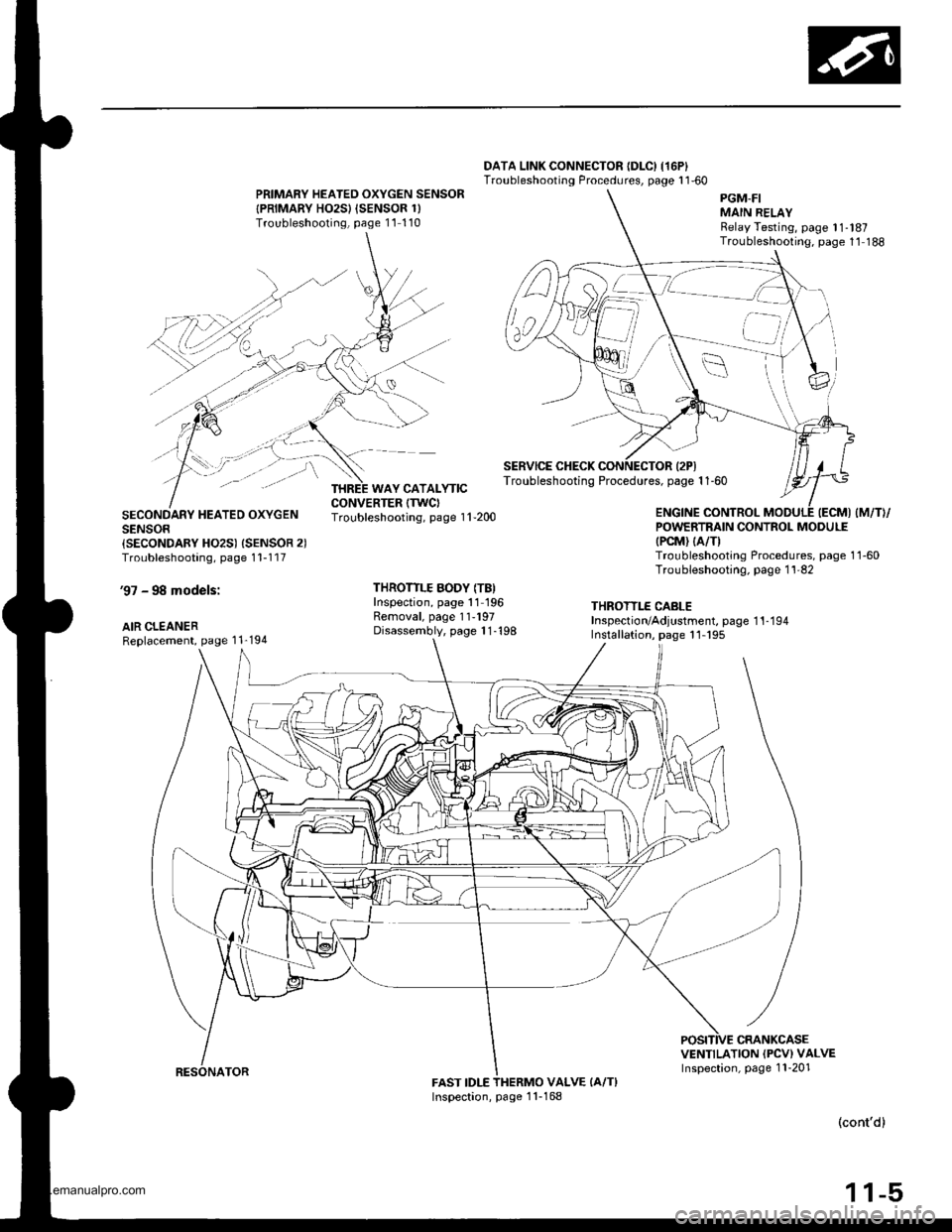
DATA LINK CONNECTOR {DLC) I16P}Troubleshooting Procedures, page 1 1'60PRIMARY HEATED OXYGEN SENSOR
{PRIMARY HO2SI {SENSOR 1)Troubleshooling, page 11 110
SECONDARY HEATED OXYGENSENSOR{SECONDARY HO2S) {SENSOR 2)Troubleshooting, page 1 1-1 17
'97 - 98 models:
AIR CLEANERReplacement, page 1 1'194
Troubleshooting, page 1 'l -200
THROTTLE BODY (TB)Inspection, page 11 196Removal, page 11-197Disassembly, page 1 1-'198
POWERTRAIN CONTROL MODULE(PCM) (A/TI
Troubleshooting Procedures, page 1 1-60Troubleshooting. page 1 1'82
THROTTLE CABLEInspection/Adjustment, page 1 1-1 94Installation, page 11- 195
VENTILATION (PCV) VALVEInspection, page 1 1-201FAST IDLEVALVE (A/T}
(cont'd)
1 1-5
PGM-FIMAIN RELAYRelay Testing, page 11-l87Troubleshooting. page 1'1 188
SERVICE CHECK CONNECTOR {2PITroubleshooting Procedures, page 1 1-60
,a'=_-_
WAY CATALYTIC
Inspection, page 1 1-168
www.emanualpro.com
Page 209 of 1395
Component Locations
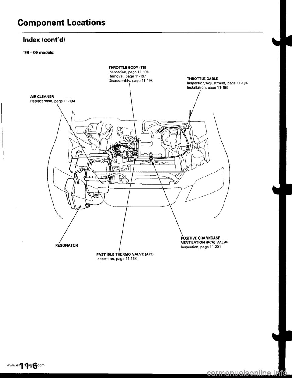
Index {cont'd)
39 - q, models:
THROTTLE BODY ITB)Inspection, page 1 1-196Removal, page 11- 197Disassembly, page 11 198THROTTLE CABLEInspectaon/Adjustment, page 1 1 194Installation, page I l'195
AIR CLEANERR€placomenl, page 1 1-194
CRANKCASEVENTILATION IFCVI VALVElnspection, page 11 201
FAST IDLE THERMO VALVE IA/T)Inspection, page 11'168
1 1-6
www.emanualpro.com
Page 215 of 1395
System Description
I
I
I
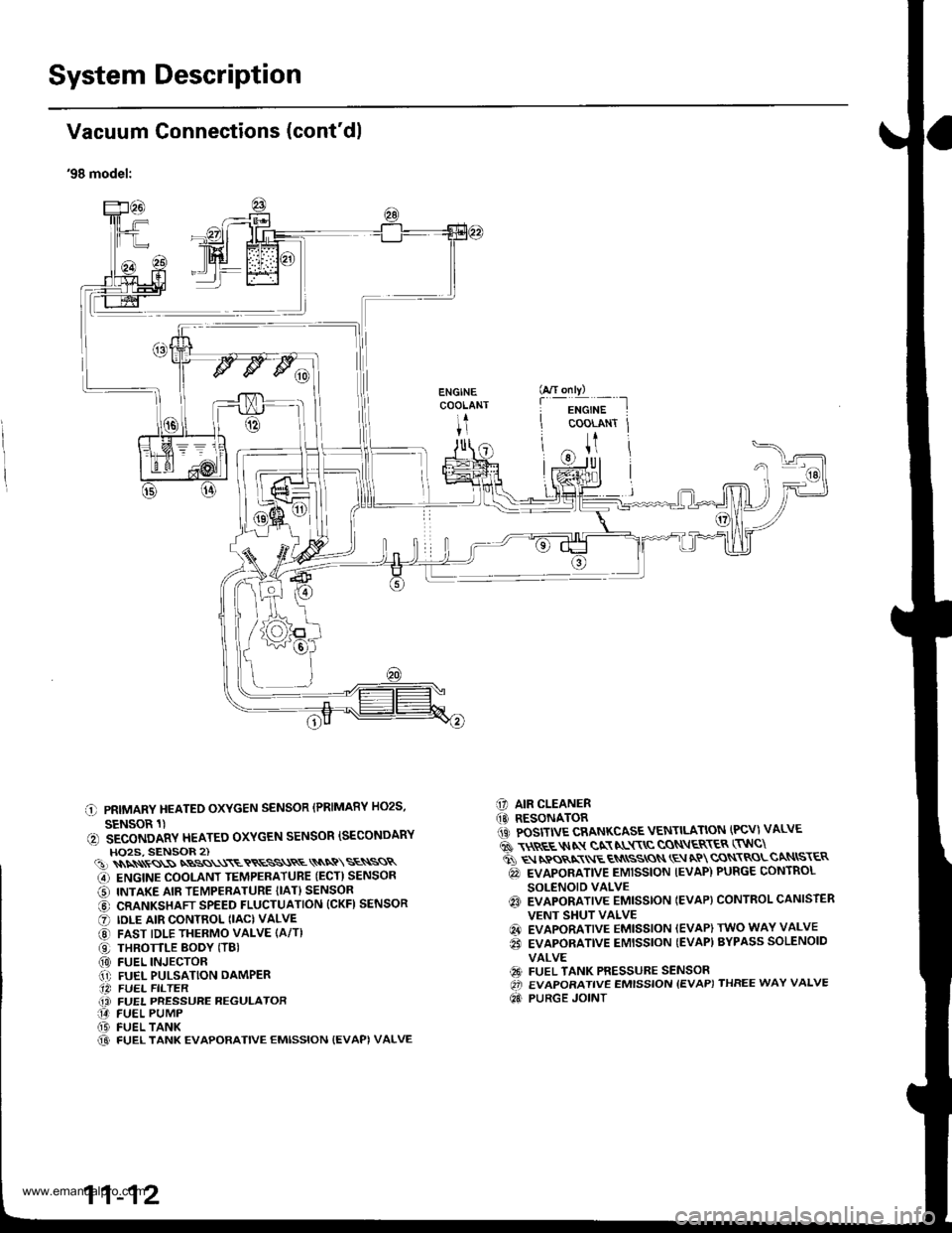
Vacuum Connections (cont'dl
'98 model:
C PRIMARY HEATEO OXYGEN SENSOR (PRIMARY HO2S,
SENSOR 1)(, SECONDARY HEATEO OXYGEN SENSOR ISECONDARYHO2S, SENSOR 2)(!)\\\\ss\SNBSS\\\ETRESS\RE\\NQ\SE\SSR
G) ENGINE COOLANT TEMPERATUBE (ECT) SENSOR
O INTAKE AIR TEMPERATURE {IAT} SENSOR
@ CRANKSHAFT SPEED FLUCTUATION (CKFI SENSOR
O IDLE AIR CONTROL (IAC) VALVE
@ FAST IDLE THERMO VALVE (A/T)
O THROTTLE BODY (TBI(0) FUEL INJECTOR.1' FUEL PULSATION DAMPER.14 FUEL FILTER(i FUEL PRESSURE REGULATOR14 FUEL PUMP(D FUEL TANK@ FUEL TANK EVAPORATIVE EMISSION {EVAPI VALVE
C] AIR CLEANER(O RESONATOR1iC POSITIVE CRANKCASE VENTILATION (PCV) VALVE
6 \$REE$IN gN NL$\C CON\ER\ER (TNC\
ti q rpos,xr E qN
ssros \E aP cqN\RoLcaNtsr€R
@ EVAPORATIVE EMISSION IEVAP) PURGE CONTROL
SOLENOID VALVEq3 EVAPORATIVE EMISSTON IEVAP} CONTROL CANISTER
VENT SHUT VALVE
@ EVAPORATIVE EMISSION (EVAP) TWO WAY VALVE
€i EVAPORATIVE EMISSION {EVAP) BYPASS SOLENOID
VALVE
€9 FUEL TANK PRESSURE SENSOROi EVAPORATIVE EMISSION {EVAP) THREE WAY VALVE
Qd PURGE JOINT
G/T only)
f
-i*'";-t
COOLANT Jt
U
11-12
www.emanualpro.com
Page 217 of 1395
System Description
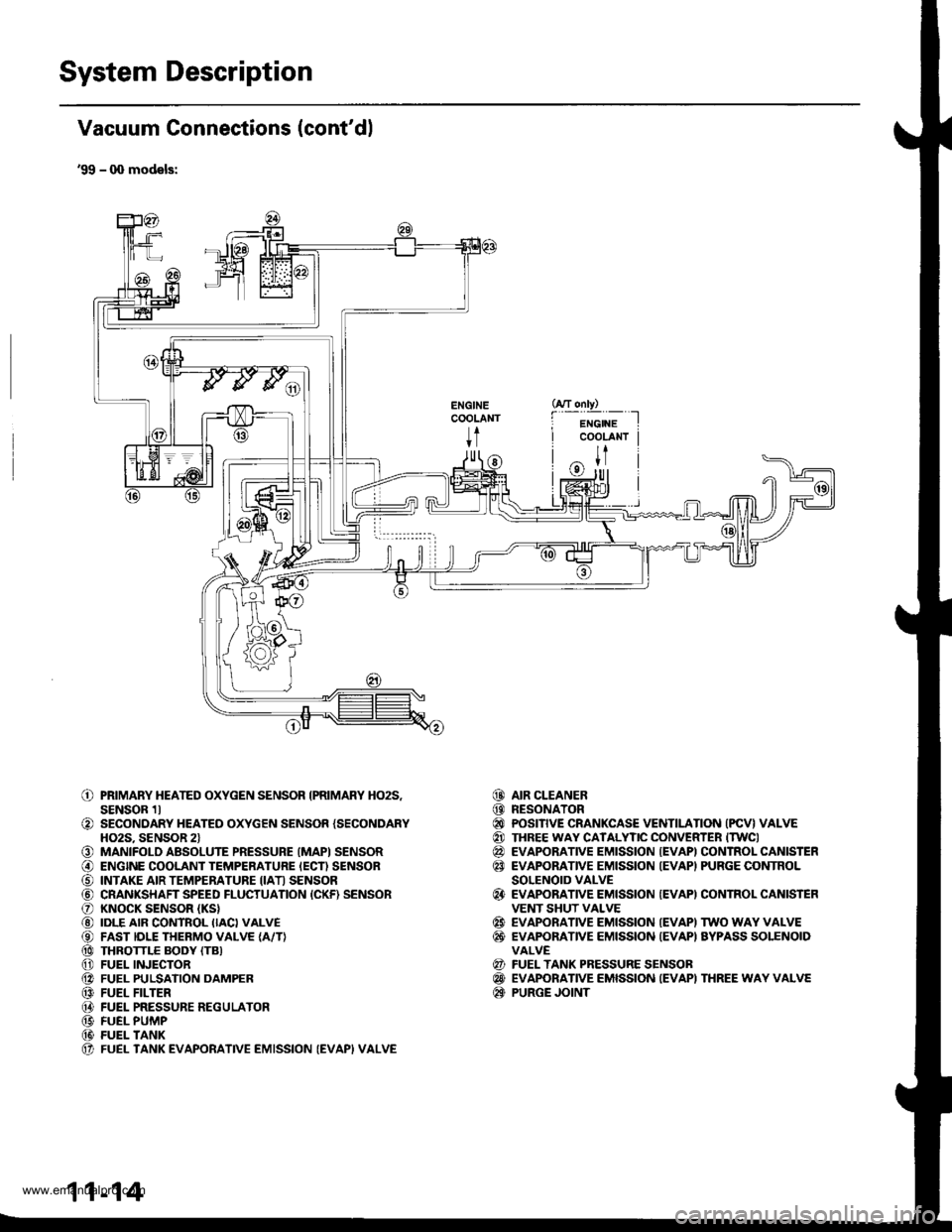
Vacuum Connections (cont'dl
'99 - q) models:
ENGINECOOLANT
t
o
o
o@
o@@@@@@@@@(t
PRIMARY HEATED OXYGEN SENSOR IPRIMARY HO2S,SENSOR 1lSECONDARY HEATED OXYGEN SENSOR {SECONDARYHO2S. SENSOR 2lMANIFOLD ABSOLUTE PRESSURE (MAPI SENSORENGINE COOLANT TEMPERATURE IECN SENSORINTAKE AIR TEMPERATURE IIATI SENSORCRANKSHAFT SPEED FLUCTUATION {CKF) SENSORKNOCK SENSOR (KS}
IDLE AIR CONTROL IIACI VALVEFAST IDLE THERMO VALVE {A/T}THROTTLE BODY (TB}
FUEL INJECTORFUEL PULSATION DAMPERFUEL FILTERFUEL PRESSURE REGULATORFUEL PUMPFUEL TANKFUEL TANK EVAPORATIVE EMISSION (EVAPI VALVE
AIR CLEANERRESONATORPOSITIVE CRANKCASE VENTILATION (PCV} VALVETHREE WAY CATALYTIC CONVERTER ITWCIEVAPORATIVE EMISSION {EVAPI CONTROL CANISTEREVAPORATIVE EMISSION IEVAPI PURGE CONTROLSOLENOID VALVEEVAPORATIVE EMISSION {EVAPI CONTROL CANISTEFVENT SHUT VALVEEVAPORATIVE EMISSION IEVAPI TWO WAY VALVEEVAPONANVE EMISSION {EVAPI AYPASS SOLENOIDVALVEFUEL TANK PRESSURE SENSOBEVAPORATIVE EMISSION IEVAPI THREE WAY VALVEPURGE JOINT
@@@@@@
@
@@
@@@
11-14
www.emanualpro.com
Page 266 of 1395

Troubleshooting
Troubleshooting Procedures (cont'dl
Symptom Chart
Listed below are symptoms and probable causes for problems that DO NOT cause the Malfunction Indicator Lamp (MlL) tocome on. lf the MIL was reported on, go to page 11-60.Troubleshoot each probable cause in the order listed (from left to right) until the symptom is eliminated,The probable cause and troubleshooting page reference can be found below.
Other Probable Causes for an engine that will not start:- Compression- Intake air leakage- Engine locked up- Timing belt- Starting system- Overheating- Battery
SYMPTOMPROBABLE CAUSE
Engine will not sta rt4, 2,3,5,20, 't5, 1
Hard starting2, 4, 12,17, 14, 't9
Cold fast idle too low7, a,9, 6, 17
Cold fast idle too high7,8,9,11,10
ldle speed fluctuates9,7,8, 't1, 10
Misfire or rough runningTroubleshoot for misfire on pages '11-126, 1|21LOl/\/ power2, 10,11, 13, '17, 18,20
Engine stalls2, 4, 12,1,20,9,5, 't6
Probable Cause List (For the DTC Ch8rt, see page ll-75.)
Probable CausePageSystem
Engine controt ruoaute (ecvtffi'I11-42
I 1-178Fuel oressure
PGM-Fl main relav
lgnition system
Crankshatt Position/Top Dead Center/Cylinder position sensor circuit
Intake Air Temperature (lAT) sensor ctrculr
ldle Air Control (lAC) Vatve
Fast idle thermo valve
ldle speed adjustment
Throttle body
Throftle cable
Manifold Absolute P."""rr"ffi
Throftle Position (TP) sensor
Barometric pressur" (gnno-
Ay'T gear position signal
Brake switch signal
Air Cleaner
Three Way Catalytic Converter (TWC)
Evaporative emission (EVAP) control
Contaminated fuel
1 1- 187
Section 4
5't1-'t31,146
6I '�t-95
711-152
81'l-168
1 1- 169
1011-196'1111-'194
12'1 'l -90
1 1- 103
1411-137
15Section 14
161 1- 166
17r 1-194
181 1,199'1911-203
20
11-64
www.emanualpro.com
Page 279 of 1395
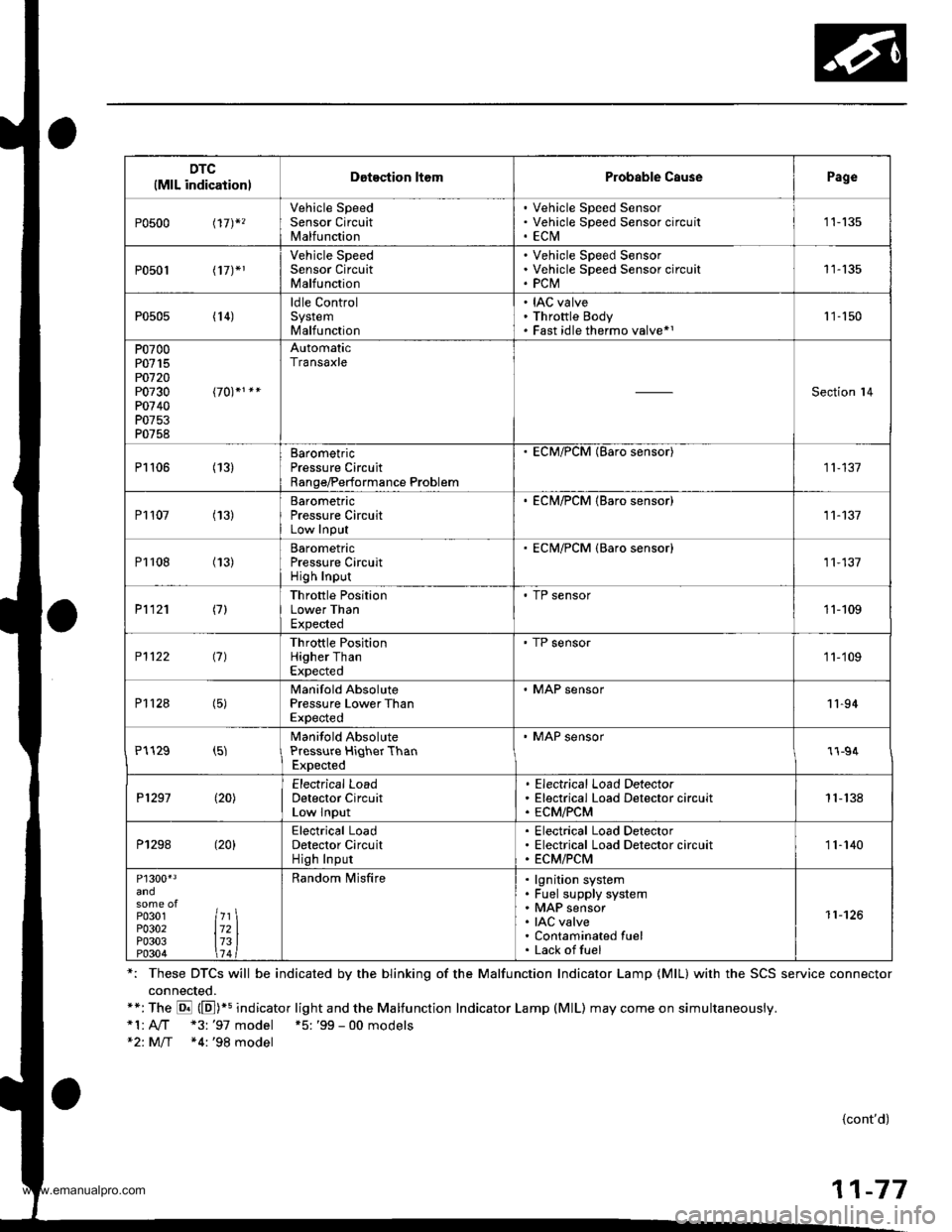
DTC(MlL indicationlDotection ltomProbable CausePage
P0500 t17)*,
Vehicle SpeedSensor CircuitMalfunction
Vehicle Speed SensorVehicle Speed Sensor circu itECtVI1 1-135
P0501 l17J*1
Vehicle SpeedSensor CircuitMalfunction
Vehicle Speed SensorVehicle Speed Sensor circuitPCM11-135
P0505 (14)ldle ControlSystemMalfunction
IAC valveThrottle BodyFast idle thermo valve*11 '�]- 150
P0700P0715PO720P0730P0740P0753P0758
AutomaticTransaxle
Section l4
P1106 (13)BarometricPressure CircuitRange/Performance Problem
ECM/PCM (Baro sensor)
11-137
P1107 (13)BarometricPressure CircuitLow InPut
. ECM/PCM {Baro sensor)11-137
P1108 (13)BarometricPressure CircuitHigh Inpur
ECM/PCM {Baro sensor)11,137
P1121 (7)Throttle PositionLower ThanExpected
. TP sensor11-109
P1122 (7)Throttle PositionHigher ThanExpected
' TP sensor1 1-'109
P112a (5)Manifold AbsolutePressure Lower ThanExpected
. MAP sensor11-94
P1129 (5)Manifold AbsolutePressure HiqherThanExpected
' MAP sensor1l-94
P1297 (20)Electrical LoadDetector CircuitLow Input
Electrical Load DetectorElectrical Load Detector circuitECM/PCM1 1- 138
P1298 (20)Electrical LoadDetector CircuitHigh Input
Electrical Load DetectorElectrical Load Detector circuitECM/PCM11-140
P1300'3
P0301P0302P0303P0304
7l721314
Random lvlisfirelgnition systemFuel supply systemMAP sensorIAC valveContaminated fuelLack offuel
11-126
*: These DTCS will be indicated by the blinking of the Malfunction Indicator Lamp {MlL} with the SCS service connector
connected.**:The E (E])+s indicator light and the Malfunction Indicator Lamp (MlL) may come on simultaneously.*1:A,./T "3: '97 model +5: '99 - 00 models*2: M/T *4:'98 model
{cont'd)
11-77
www.emanualpro.com
Page 314 of 1395
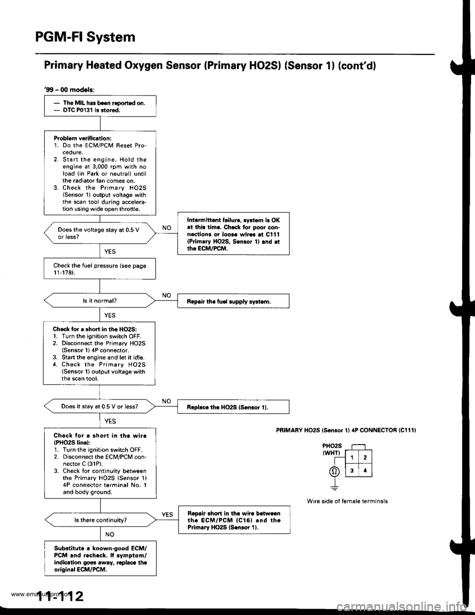
PGM-FI System
'99 - 00 models:
- The MIL has bsen reported on.- DTC P0131 ir storod.
Problem ve fication:1. Do the ECM/PCM Reset Pro-cedure,2. Start the engine. Hold theengine at 3,000 rpm with noload {in Park or neutral) untillhe radiator tan comes on.3. Check the Primary HO2S(Sensor 1) oltput voltage withthe scan tool during accelera-tion using wide op€n throttle.
Inl.rmittant failura, 3yrtam i! OKat thb tim.. Ch.ck tor poor con-nectiona oa looaa wlraa al C111{Pri|n.ry HO2S, Son3or 1l .nd .ttho ECM/FCM,
Does the voltage stay at 0.5 Vor less?
Check tho fuel pressure (see pago1r,178).
R.p.ir th. fu€l lupply ry!t.m.
Chock lor a short in tho HO2S:1. Turn the ignition switch OFF.2. Disconnect the Primary HO2S(Sensor 1) 4P connector.3. St6rt the engine and lot it idle.4. Check the Primary HO2S(Sensor 1) output voltage withthe scan tool,
Does it stay 6t 0.5 V or less?Rephc. th6 HO2S (S.n3or 11.
Chock for a short in tho wirc(PHO2S lino):1. Turn the ignition switch OFF.2. Disconnect the ECM/PCM con-nector C (31P).
3. Check tor continlity betweenthe Primary HO2S {Sensor 'l}
4P connector terminal No. Iand body ground.
Ragah rhort in tha wira balwoanth. ECM/PCM {Cl61 rnd thcPrirn.ry HO2S (S.n3or 11.
Substltut6 a known-good ECM/PCM and recheck. lf rymptom/indicrtion 00os away, raplaco thcoriginal ECM/PCM.
Primary Heated Oxygen Sensor (Primary HO2SI (Sensor 1l (cont'd)
PRIMARY HO2S (Son.or 1l aP CONNECTOR |C111)
PHO2S T--1rwHTr f-T---]
--1 1 2lI t--- 1t6)lslrlv L__r__J
_L
Wire side ol female terminals
11-112
www.emanualpro.com
Page 352 of 1395

ldle Control System
ldle Control System
I P0505 | The scan tool indicates Diagnostic T.ouble Code (DTCI PO5O5: ldlecontrol svstem mattunction.
NOTE: lf DTC P1508 is stored at the same time as DTC P0505, troubleshoot DTC P1508 first. then troubleshoot DTC p0505.
Possibls Cause
. IAC valve mechanical malfunction. Throttle body clogged port, improper adlustment. Intake manifold gasket leakaging. Intake air hose loose leakaging. Vacuum hose leakaging
a ECT sensor incorrect output. Throttle Position sensor incorrect output
Troubleshooting Flowchart
The MIL has been reDorted on.DTC P0505 is sto.ed.
Problem verificationi1. Start the engine. Hold theengine at 3,000 rpm with noload (in Park or neutral) untilthe radiator Ian comes on, thenlet it idle.2. With the scan tool, check thelollowing items.- Throttle position should beapprox. 10% with the throt-tle {ully closed.- Engine coolant temperature shorJld be 194 - 205'F(90 - 96"C).lf they are not within thespec., repair the faulty sen-sor circuit.3 Check the engine speed atidle with no-load conditions:headlights, blower fan. reardefogger, radiator lan, and airconditioner are not operaling,
Inte.mittent failure. syltem is OKat this time.ls it 750 {730)* i 50 rpm?
ls il 700 (680)' rpm or less?
{To page 11-151)(To page 1'l-151)
l:'99 - 00 models
www.emanualpro.com
Page 353 of 1395
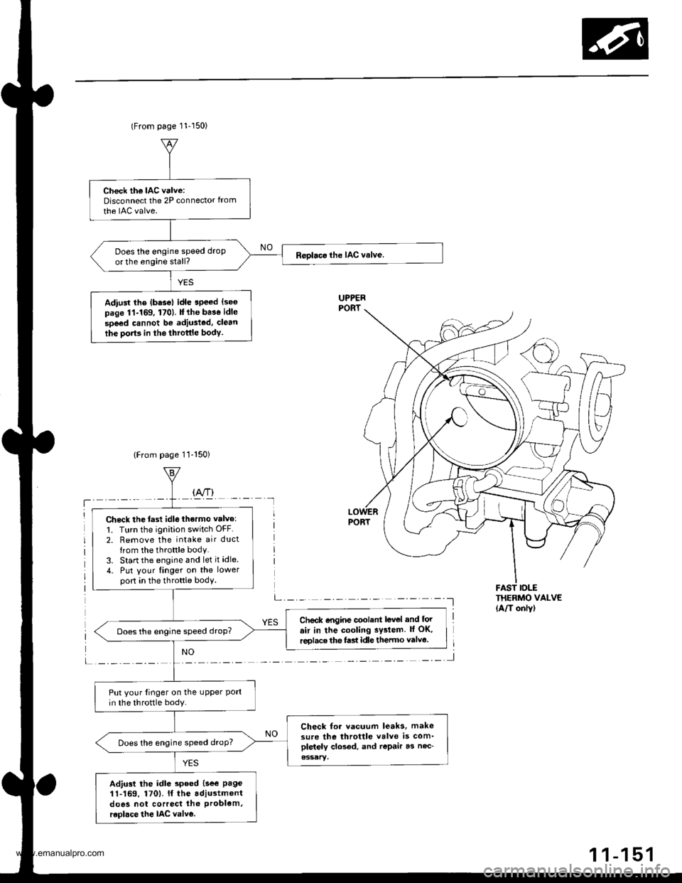
(From page 11-150)
{From page 11-150}
THERMO VALVE(A/T onlyl
Check the IAC valve:Disconnect the 2P connector from
the IAC valve.
Does the engine speed droP
or the engine stall?
Adiust the (basel idl€ speed lseepage 11-169, 1t0). Itihe ba3e idle
speed cannot be adiust€d, clean
the Dorts in the throttle body.
UPPER
Check the tast idle lhermo valve:
1. Turn the ignition switch OFF.
2. Remove the intake air ductfrom the throttle body.3. Start the engine and let it idle.
4. Put your finger on the lowerpon in the throttle body.
Check engine cool.nt level and for
air in the cooling sy3lem. lf OK,
reolace the f.st idle thermo valve.Does the engine speed drop?
Put your Iinger on the uPPer Portin the throttle body.
Check for vacuum leaks, make
sure the throttle valve is com'pletely clo3ed. and repair as nec-Does the engine speed droP?
Adjust the idle spoed lsee Page11-169. 1701. lf the adiustmentdoes not correct lhe problem,
r.olace the IAC valve.
www.emanualpro.com