Valve HONDA CR-V 1999 RD1-RD3 / 1.G Workshop Manual
[x] Cancel search | Manufacturer: HONDA, Model Year: 1999, Model line: CR-V, Model: HONDA CR-V 1999 RD1-RD3 / 1.GPages: 1395, PDF Size: 35.62 MB
Page 17 of 1395
![HONDA CR-V 1999 RD1-RD3 / 1.G Workshop Manual
Under-hood Emissions Control Label
Emission Group ldentification
(1997 modell
Example:
VACUUM HOSE ROUTING DIAGRAM
LOADED IM TEST]NG OF PERMANENT fOUB WHEEL OSVE OR TRACT ON CONTROLEOLJIPPEDVEHTCLES HONDA CR-V 1999 RD1-RD3 / 1.G Workshop Manual
Under-hood Emissions Control Label
Emission Group ldentification
(1997 modell
Example:
VACUUM HOSE ROUTING DIAGRAM
LOADED IM TEST]NG OF PERMANENT fOUB WHEEL OSVE OR TRACT ON CONTROLEOLJIPPEDVEHTCLES](/img/13/5778/w960_5778-16.png)
Under-hood Emissions Control Label
Emission Group ldentification
(1997 modell
Example:
VACUUM HOSE ROUTING DIAGRAM
LOADED IM TEST]NG OF PERMANENT fOUB WHEEL OSVE OR TRACT ON CONTROL'EOLJIPPEDVEHTCLES MUST BE CONDUCTED ON A IOUR WHEEL DR VE SPEEO SYNCHRON ZED
ANON LOADEDTESTPBO(EOUBEMUSIBEPERFORMEO
50ST (50 Statesl:
THIS VEHICLE CONFOBMS TO U.S. EPA AND STATE OF
CALIFORNIA REGULATIONS APPLICABLE TO 1997
MODEL YEAR NEW LIGHT DUTY TRUCKS.
49ST {49 Statos/Federall:
THIS VEHICLE CONFORMS TO U.S. EPA REGULATIONS
APPLICABLE TO 1997 IVIODEL YEAR NEW LIGHT DUTY
TRUCKS.
CAL (Calitornial:
THIS VEHICLE CONFORMS TO U.S. EPA AND STATE OF
CALIFORN IA REGULATIONS APPLICABLE TO '1997
MODEL YEAR NEW TLEV LIGHT DUTY TRUCKS
PROVIDED THAT THIS VEHICLE IS ONLY INTRODUCED
INTO COMMERCE FOR SALE IN THE STATE OF
CALIFORNIA.
Ii/PORTANT VEHICLE INFORIMATIONENGINE FAMILY VHN2 OIJCrcKDISPIACEMENT'2 OLITEREVAPORAT VE f AM]LY VNNl0778YMBP
CATALYSTREfERTOSEBVICEMANUALfORAODITIONAL NFORMATON.TUNT I-]P CONDITIONSENGINE AT NORI\,!AL OPERATNG TEMPERATURE,ALLACCESSOR ES TL]RNED OFF COOLING FAN OIFTRANSM1SSION NNEUTRALNO OTHEB ADJUSTMENIS NEEDED
ap' | \6( Zror '. ND \. 61F L r
TNIS VENICLE CONFORMS TO U.S EPA REGUI.ATIONSAPPI CASLE TO I99] MODET YEAR N€W L GNI DUTY TRACKS
@
Engine Family: vHN2.o l JGKE
Engine and Evaporative Families
T_fT
Model Year I Iv:1s97 | LManufaqturer iHN: Honda I
Displacement
Class
1: Light Duty Vehicle
Fuol Systom ,nd Numb€r of valves
J: Electronic Sequential Multiport
Injection (three or more valves per
cylinder)
Fuel Type
G: Gasoline
Standard
F: 49 or 50 States Tier 1
K: 49 or 50 States Tier 1
1: California Tier 1
2: California TLEV
3: California LEV
4: California ULEV
"r0", "*,
T|
V: 1997
Manufacturer
HN: Honda
Catalyst
E, F, G, H: Three Way Catalyst
OBD
K - T: OBD Equipped
Evaporative Family:
Storago System
1: Canister
Canistor Working Capacity (gramsl
Canister Conf igulation
A: Plastic Housing (Closed Bottom)
B: Plastic Housing (OPen Bottom)
Fusl System
Y: Fuel Injection
FuelTank
M: Metal
Standard
A: Current Evap
B: Enhanced Evap
Wild C.rd
VHNlOTTBYMBP
1-1 5
www.emanualpro.com
Page 19 of 1395
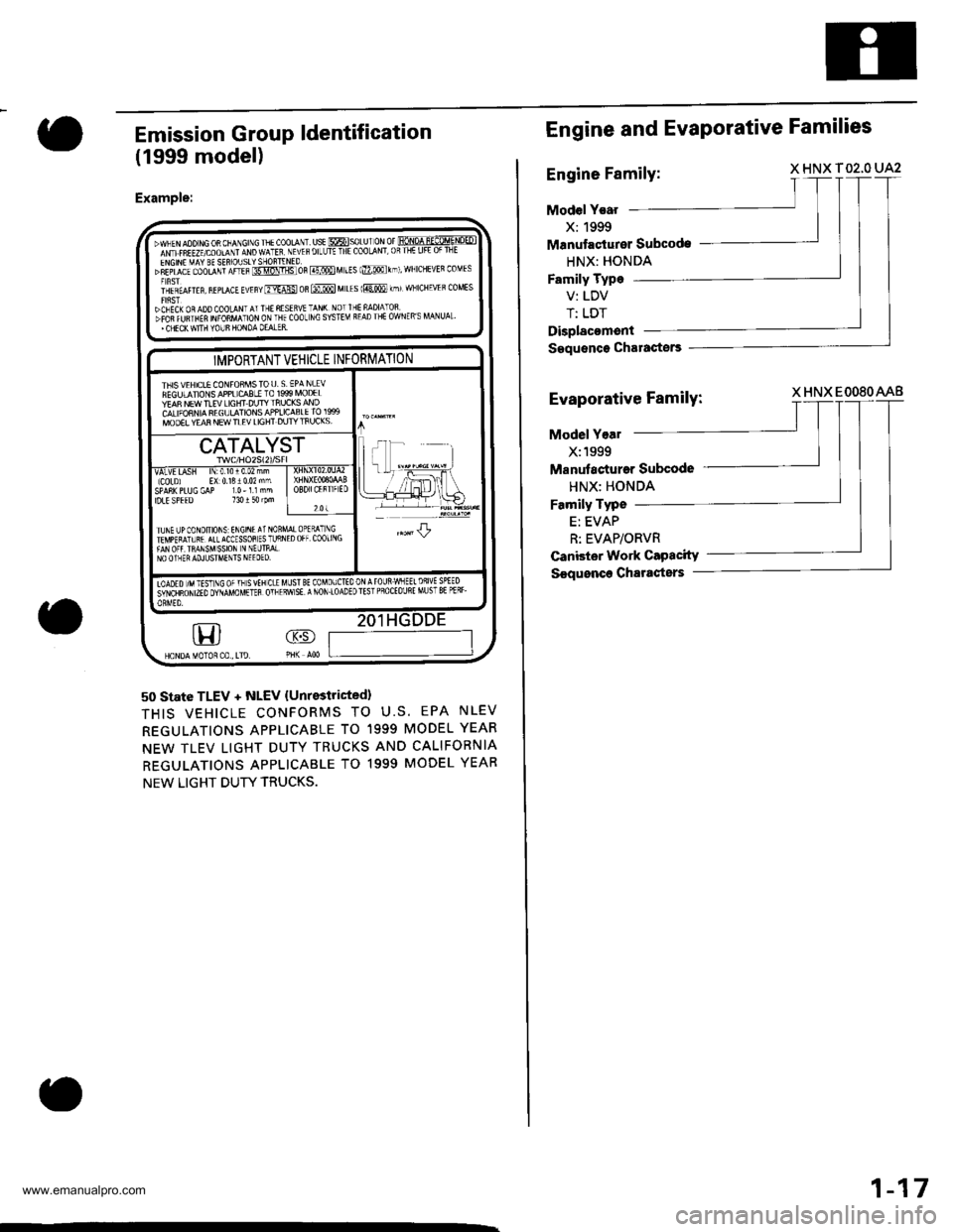
Emission Group ldentification
(1999 model)
Example:
50 state TLEV + NLEV {Unrestricted}
THIS VEHICLE CONFORMS TO U.S. EPA NLEV
REGULATIONS APPLICABLE TO 1999 MODEL YEAR
NEW TLEV LIGHT DUTY TRUCKS ANO CALIFORNIA
REGULATIONS APPLICABLE TO 1999 MODEL YEAR
NEW LIGHT DUTY TRUCKS.
'.WNEN AOO NG OR CNANGINC THE COOLANT. USE @SOLU I ON Of FONOA U-ECo-q.�NOEDImcrtniuvcoourr mo wlttt NEVEF oILLJTE THE CooLANT,0RTHE LIFE 0F TNE
"Eifil:$o""niii?i,THffi ffi'"R @ M LEs lmo rhl, wNrcHEVEn coMEs
i'lrt^t orrrr, ^,r*a, rurr"* os @ M LEs 1@ kmr wNICHEVER coMEs
}CNECK OR ADD COOLANT AT THE RESER!'E TAN( NOT IHE NADIATOSDFOfi fWTHEF NFORMATION ON THE COOL NC SYSTEM READ THE OWNER'S MANUAL'' CHECK WIIH YOUS HONOA OEALER.
GD
IMPORTANT VEHICLE INFORMATION
THIS VEHICLE CONFOAMSTOU. S EPA NLEVFEGULANONS APPLICCBLI TO 1999 MOD€LYEA8 NEW TIEV LIGHT DUTY ]nUCKS ANDCALIFORNIA REGULATIONS APPLICASLE IO 19S9MOOEL YEAR NEW TLEV LIGHT DUTY IFIJCKS,,|F --'-
Ll: .-.-,1
I rFrll\=#_H*
CATALYST
VALVE IASN lN:010r0.02 mmlCoLDj EX 0131002 mmSPA8K PLUG GAP 10- l l nmIDLE SPEED 130 t 5{ rPmOBDIICERT]ATD
201
TUNE I]PCONDIIIONS INGINEAT NOBTEI\'PERATUR€ ATL ACCESSOS ES TLJRNFAN OFf IRANSMSSION N NEL]TMLNO OINER ADJUSTMTNTS NEEOEO.
JL
Iooro nr tist rc orn svtncrE MUsT BE coMoufitooNArounwNEElDslvE SPEEDiitriunor mo ovuvo uenn orr Enw sE a NoN.loaDE D rEsr PRoCE ouRE MU sT 8E Pf Rr-
Engine and Evaporative Families
Engine Family:X HNX T02,O UA2
Model Year
X:1999
Manutao{urer Subcode
HNX: HONDA
Family Type
V: LDV
T: LDT
Displacoment
Saquence Charactors
Evaporative Family:X HNX EOO8OAAB
Model Yoal
X:1999
Manutacturar Subcode
HNX: HONDA
Family Typo
E: EVAP
R: EVAP/ORVR
Canbter Work Capacity
S€quonce Chartsters
1-17
www.emanualpro.com
Page 27 of 1395
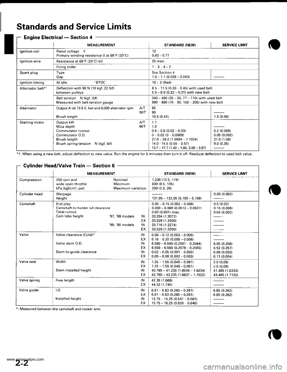
MEASUREMENTSTANDAFD INEWISERVICE LIMIT
lgnition coilRated voltage VPrimary winding resistance 0 at 68'F (20'C)120.63 0.77
lgnition wireBesistance at 68"F (20 C) ktl25 max.
Firing order1 3 4-2
Spark plugTypeGapSee Section 41.0 - 1.1 (0.039 - 0.043)
lgnition timingAt idle BTDC161 2 {Red)
Alternator belt*rDeflection with 98 N {10 kgf, 22 lbf)8.5 11.510.33 0.45)with used belt5.5 - 8.0 (0.22 - 0.31) with new belt
Belt tension N {kgf, lbt)Measured with bek tension gauge340 - 490 {35 - 50, 77 110) with used belt690 880 (70 90, 150 - 200i with new belt
AlternatorOutput A (at 13.5 V, hot and 6,000 alternator rpm AIIM/IBrush length
959010.5 (0.41)1.5 (0.06i
Staning motorOutput kW A/fMica depth MfiCommutator runoutCommutator O.D.Brush lengthBrush spring tension N (kgf, lbf)
1.11.00.5 - 0.8 {0.02 - 0.03)0,0.02 (0 0.0008)27.9 28.0 (1.0984 1.1024)14.0 14.5 (0.55 0.57)13.7 - 17.7 (1.40 - 1.80,3.09 - 3.97)
0.2 (0.008)
0.0s (0.002)
27.0 (1.06)
9.0 (0.35)
Standards and Service Limits
Engine Electrical - Section 4
'1 When using a new belt, ddiust deflection to new value. Run the engine for 5 minutes then turn it of{. Beadiust deflection to used belt value.
Cylinder Head/Valve Train - Section 6
MEASUREMENTSTANDARD {NEW} SERVICE LIMIT
Compression250 rpm and Nominalwide open throttle MinimumkPa (kgflcm'�, psi) Maximum variation
1 ,230 i'12 .5 , 11Al930 (9.s, 135)200 12.0,2al
Cylinder headWarpageHeight131.95 - 132.05 {5.195 - 5.199)0.05 {0.002)
CamshaftEnd playCamshaft to hoider oil clearanceTotal runoutCam lobe height '97,'98 models lNEX'99,'00 models lNEX
0.05 0.1s (0.002 0.006)0.030 - 0.069 (0.0012 - 0.0027)0.03 {0.001)max.33.204 \1.3072133.528 {1.3200)33.1 16 \1 .321 4)33.528 {'1.3200)
0.5 (0.02)
0.15 (0.006)
0.04 (0.002)
Valve clearance (Cold)* lNEXValve stem O.D. lNEXStem'to-guide clearance lNEX
0.08 - 0.12 (0.003 0.005)0.16 0.20 (0.006 - 0.008)6.580 - 6.590 (0.2591 0.2594)6.550 - 6.560 (0.2579 0.2s83)0.02 - 0.05 {0.00t 0.002)0.05 - 0.08 (0.002 0.003)
u* to.rutt6.52lO.257l0.08 {0.003i0.'1t (0.004)
width tNEXStem installed height lNEX
1.25 - 1.55 (0.049 - 0.061)1.25 1.55 (0.049 - 0.061)40.765 - 41.235 {1.6049 1.6234)42.765 - 43.235i'1.6837 - 1.70221
2.0 (0.08)
2.0 (0.08)
41.485 {1.6333}43.485 {1.7120i
Valve springFree length lNEX42.36 (1.668i
44.32 t1 .1 451
Valve guideI,D, INEXInstalled height tNEX
6.61 6.63 10.260 - 0.261)6.61 6.63 {0.260 - 0.261i13.75 - 14.25 10.541 0.561i15.75 - 16.25 {0.620 0.640i
6.6510.26216.65 (0.262i
*: Measured between the camshaft and rocker arm,
2-2
www.emanualpro.com
Page 29 of 1395
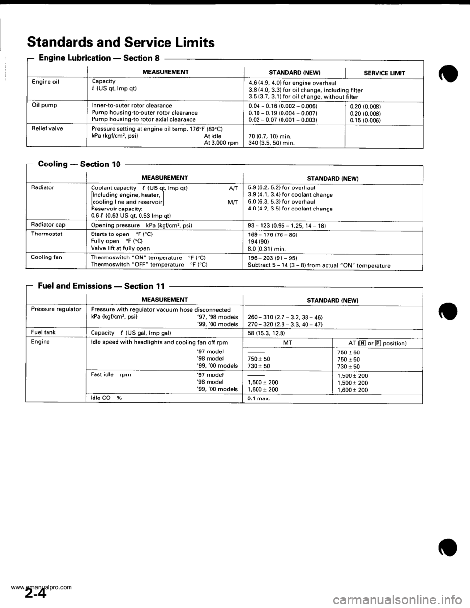
Standards andService Limits
Engine LubricationSection 8
CoolingSection 10
Fuel and EmissionsSection 11
MEASUREMENTSTANDARO {NEWISERVICE LIMIT
Engine oilCapacityf (US qt, lmp qt)4.6 (4.9, 4.0)Ior engine overhaul3.8 {4.0,3.3)for oilchange, including filter3.5 (3.7, 3.1) for oil change, without Iilter
OilpumpInner-to-outer rotor clearancePump housing-to-outer rotor clearancePump housing-to rotor axial clearance
0.04 - 0.16 (0.002 - 0.006)0.10 -0.19 (0.004 - 0.007)0.02 -0.07 (0.001 - 0.003i
0.20 (0.008)
0.20 (0.008)
0.15 (0.006)
Relief valvePressure setting at engine oil temp. 176'F (80'C)kPa (kgt/cm,, psi) At ldleAt 3,000 rpm70 (0.7, 10) min.340 {3.5,50) min.
MEASUREMENTSTANDARO INEW}
RadiatorCoolant capacity , (US q1, lmp qt)
llncluding engine, heater, ILcooling line and reservoirlReservoir capacity:0.61 (0.63 US qt,0.53lmp qt)
M/T
5.9 {6.2, 5.2}tor overhaul3.9 (4.1, 3.4ifor coolant change6.0 (6.3, 5.3ifor overhaul4.0 (4.2, 3.5) for coolant change
Radiator capOpening pressure kPa (kgf/cm?, psi)93 - 123 (0.95 - 1.25, 14 18)
ThermostatStarts to open 'F 1"C)Fully open 'F ("C)
Valve lift at tully open
169 - 176 (76 - 80)194 (90)
8.0 (0.31imin.
Cooling fanThermoswitch "ON" temperature "F {'C)Thermoswitch "OFF" temperature 'F ('C)196 - 203 (91 - 95)Subtract 5 - 14 (3 - 8) trom actual "ON" temperature
MEASUREMENTSTANDARD INEW}
Pressure regulatorPressure with regulator vacuum hose disconnectedkPa (kgflcm'�, psi) '97,'98 models'99, '00 rnodels260 - 31012.7 3.2,38- 46)270 -32012.8 3.3,40 - 471
FueltankCapacity / (US gal, lmp gal)58 (15.3, 12.8)
E ngineldle speed with headlights and cooling fan off rpm'97 model'98 model'99, '00 models
MTAT {E or E position)
750 r 50730 1 50
750 t 50750 r 507301 50
Fast idle rpm '97 model'98 model'99, '00 models1,5001 2001,600 r 200
1,5001 2001,5001 2001,600 r 200
ldle CO %0.1 max.
2-4
www.emanualpro.com
Page 34 of 1395
2-9
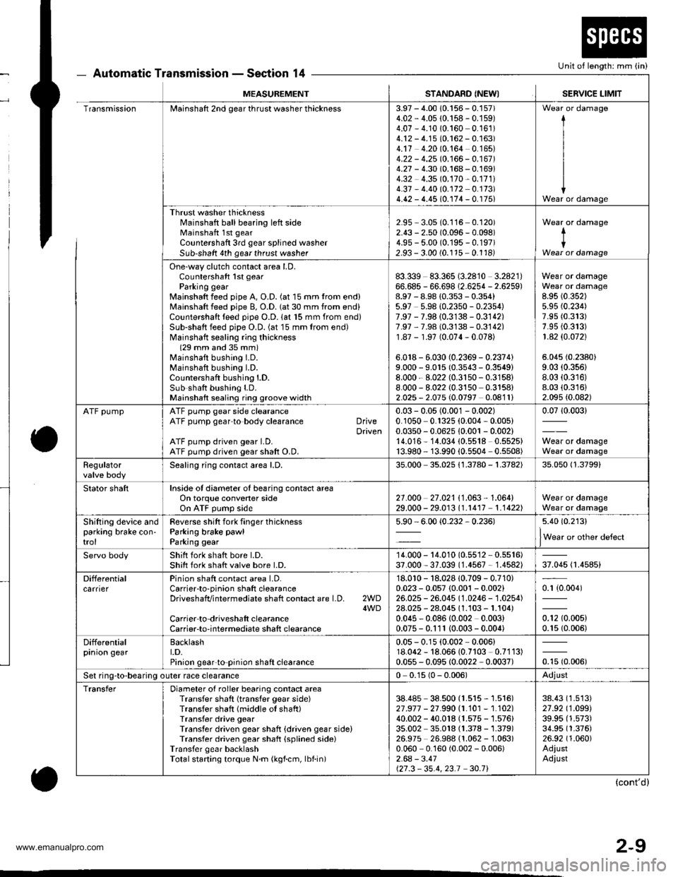
Automatic Transmission - Section 14
o
Unit of length: mm (in)
o
MEASUREMENTSTANDARD (NEWISERVICE LIMIT
TransmissionMainshaft 2nd gear thrust washer thickness3.97 - 4.00 10.156 - 0.157)4.02 - 4.05 {0.158 - 0.159)4.07 - 4.1010.160 0.161)4.12 - 4.15 (0.162 - 0.163)4.17 4.20 (0.164 0.165)4.22 - 4.25 10.166 - 0.167 )4.27 - 4.30 (0.168 - 0.169)4.32 4.35 (0.170-0.171)
4.37 - 4.40 (0.172 0.173)4.42 - 4.45 (0.174 - 0. r75)
I
I
IWear or damage
Thrust washer thicknessl'rainshaft ball bearing left sideMainshaft 1st gear
Countershaft 3rd gear splined washerSub-shaft 4th gear thrust washer
2.95 3.05 (0.116 0.120)2.43 - 2.50 (0.096 - 0.098)4.9s - 5.00 (0.195 - 0.197)2.93 - 3.00 (0.115 - 0.1181
Wear or damage
tIWear or damage
One-way clutch contact area LD.Countershaft 1st gearParking gearMainshaft feed pipe A, O.D. (at 15 mm trom end)Mainshaft feed pipe B, O.D. (at 30 mm from end)Countershaft teed pipe O.D. lat 15 mm from end)Sub-shaft feed pipe O.D. (at 15 mm from end)Mainshatt sealing ring thickness(29 mm and 35 mm)Mainshaft bushing I.D.Mainshaft bushing l.D.Countershaft bushing l.D.Sub shatt bushing LD.Mainshaft sealing ring groove width
83.339 83.365 (3.2810 3.2821)66.685 - 66.698 (2.6254 - 2.6259)8.97 - 8.98 (0.353 - 0.354)5.97 5.98 {0.2350 - 0.2354)7.97 - 7.98 (0.3138 - 0.3142)7.97 ,7.98 (0.3138 - 0.3142)1.87 - 1.97 (0.074-0.078)
6.018 - 6.030 (0.2369 - 0.2374)9.000 - 9.015 (0.3543 - 0.3549)8.000 - 8.022 (0.3150-0.3158)
8.000 - 8.022 (0.3150 0.3158)2.025 - 2.075 (0.0797 0.0811)
Wear or damageWear or damage8.95 (0.352)
5.95 (0.234)
7.95 (0.313)
7.95 {0.313)1 .42 $.O72)
5.045 (0.2380)
9.03 (0.356)
8.03 (0.316)
8.03 (0.316)
2.095 (0.082)
ATF pumpATF pump gear side clearanceATF pump gear'to body clearance DriveDrivenATF pump driven gear LD.ATF pump driven gear shaft O.D.
0.03 - 0.05 (0.001 - 0.002)0.1050 0.1325 (0.004, 0.005)0.0350 - 0.0625 10.001 - 0.002)14.016* 14.034 (0.5518 0.5525)13.980 - 13.990 {0.5504 0.5508)
0.0710.003)
Wear or damageWear or damage
Regulatorvalve bodySealing ring contact area l.D,35.000 35.025 {1.3780 - 1.3782)35.050 (1.3799)
Stator shaftInside of diameter oI bearing contact areaOn torque convener sideOn ATF pump side2't .o00 27 .021 I '1 .063 , 1 .064)29.000 - 29.01311.r417 1.1422)Wear or damageWear or damage
Shifting device andparking brake con'trol
Reverse shitt fork finger thicknessParking brake pawl
Parking gear
5.90 - 6.00 {0.232,0.236)5.40 (0.213)
lWear or other defect
Servo bodyShift fork shatt bore l.D.Shift fork shatt valve bore l.D.14.000 - 14.010 (0.55'�l2 - 0.5516)37.000 - 37.039 (1.4567 - 1.4582)37.045 (1.4585)
DifferentialcarrierPinion shaft contact area LD.Carrierto-pinion shaft clearanceDriveshafvintermediate shaft contact are l.D. 2WD4WDCarrier to driveshalt clearanceCarrier-to-intermediate shaft clearance
'18.010 - 18.028 10.709 - 0.710)0.023 - 0.057 {0.001 - 0.002}26.025 - 26.045 (1.0246 - 1.0254)28.025 - 28.045 (1.103 - 1.104)0.045 - 0.08610.002 0.003)0.075 - 0.111 10.003- 0.004)
0.r {0.004)
0.12 (0.005)
0.15 (0.006)
Differentialprnron gearBacklasht.D.Pinion gear'to-pinion shaft clearance
0.05 - 0.15 (0.002 - 0.006)18.062 - 18.066 (0.7103 - 0.7113)0.055 - 0.095 10.0022 - 0.0037)otu to.oout
Set ring-to-bearing outer race clearance0 0.15 (0 - 0.006)Adjust
TransferDiameter of roller bearing contact areaTransfer shaft (transfer gear side)Transfer shaft (middle of shaft)Transfer drive gearTransfer driven gear shaft {driven gear side)Transfer driven gear shaft {splined side)Transfer gear backlashTotalstarting torque N.m (kgf.cm, lbf.in)
38.485 38.500 (1.515 - 1.516)27 .917 - 21 .990 |.1.101 - 1.102)40.002 - 40.018 (1.575 - 1.576)35.002 35.018 (1.378 - 1.379)26.975 26.988 (1.062 -'�l.063)
0.060 0.160 (0.002 - 0.006)2.64 - 3.41127.3 - 35.4,23.1 30.71
38.43 (1.513)
27.92 (1.099)
39.95 (1.573)
34.95 (1.376)
26.92 (1.060)
AdiustAdiust
(cont'd)
www.emanualpro.com
Page 35 of 1395
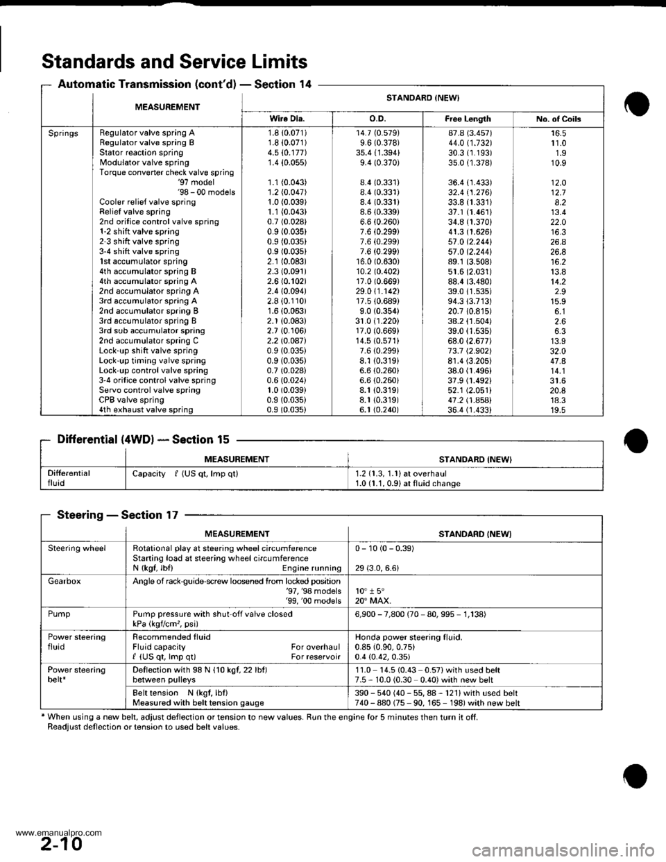
Standards and Service Limits
Automatic Transmission (cont'dl - Section 14
Differential (4WDl * Section 15
MEASUREMENTSTANOABD {NEW'
SteeringSection 17
* When using a new belt, adjust deflection or tension to new values. Run the engine for 5 minutes then turn it off.Readjust dellection or tension to used belt values.
MEASUREMENTSTANDARO INEWI
Wire Dia.o.D.Fiee LengthNo. of Coils
SpringsRegulator valve spring ARegulator valve spring BStator reaction springModulator valve springTorque convener check valve spring'97 model'98 - 00 modelsCooler relief valve springRelief valve spring2nd orilice control valve spring1-2 shitt valve spring2 3 shift valve spring3-4 shift valve spring1st accumulator spring4th accumulator spring B4th accumulator spring A2nd accumulator spring A3rd accumulator spring A2nd accumulator spring B3rd accumulator spring I3rd sub accumulator spring2nd accumulator spring CLock-up shift valve springLock-up timing valve springLock'up control valve spring3'4 orifice control valve springServo control valve springCPB valve spring4th exhaust valve spring
1.8 10.071)1.8 i0.071)4.5 (0.177)
1.4 {0.055)
1.1 (0.043)
1.2 (0.047)
1.0 (0.039)
1.1 (0.043)
0.7 (0.028)
0.9 (0.035)
0.9 (0.035)
0.9 (0.03s1
2.1 (0.083)
2.3 (0.091)
2.6 (0.102)
2.410.094)2.8 (0.110)
1.6 (0.063)
2.1 (0.083)
2.7 {0. r06)2.2lO.OA7)0.9 (0.035)
0.9 (0.035)
0.7 (0.028)
0.6 (0.024)
1.0 (0.039)
0.9 (0.035)
0.9 (0.035)
14.7 (0.579)
9.6 (0.378)
35.4 {1.394}9.4 (0.370)
8.4 (0.331)
8.4 (0.331)
8.4 (0.331)
8.6 (0.3391
6.6 (0.260i
7.6 {0.299}7.6 {0.299)7.6 {0.299)16.0 (0.630)
10.2 to.402l17.0 (0.669)
29.0 \1.1421'r7.510.689)
9.0 (0.354)
31.0 (1.220)17.0 (0.669)
14.510.571)7.610.299i8.1 {0.319}6.6 (0.260)
6.6 (0.260i
8.1 (0.319)
8.1 {0.319)6. t (0.240)
87.8 (3.457)
44.011.132130.31r.193)35.0 {1.378)
36.4 {1.433)32.4 tl.216J33.8 {r.331)37.1 (1.461)
34.8 (1.370)
41.3 (1.626)
57 .0 (2.2441
57 .0 12.244189.1 (3.508)
51.6 (2.031)
88.4 (3.480)
39.011.s35)94.313.713)20.7 10.8r5)38.2 (1.504)
39.0 (1.535)
68.0 (2.677)
73.7 12.902)8r.4 (3.205)
38.0 fl.496)37.9 (1.492)
52.1 (2.051)
41 .2 t .A5Al36.4 (1.4331
r 1.01.910.9
12.O12.78.213.422.0
26.426.8
13.814.22.915.9
2.66.3
32.047.A
20.8'18.3'19.5
Capacity f (US qt, lmp ql)1.2 (1.3, 1.1) at overhaul1.0 (1.1, 0.91 at fluid change
MEASUREMENTSTANDARD INEWI
Steering wheelRotational play at steering wheel circumferenceStaning load at steering wheelcircumferenceN {kgf, lbl) Engine running
0- 10 (0 - 0.39)
29 (3.0,6.6)
GearboxAngle of rack$uide-screw loosened lrom locked position'97, '98 models'99, '00 models10" 1 5"20" MAX.
PumpPump pressure with shut off valve closedkPa (kgvcm,, psi)6,900 - 7,800 (70 80,995 1,138)
Power steeringfluidRecommended tluidFluid capacity For overhaulI {US qt, lmp q0 For reservoir
Honda power steering fluid.0.85 (0.90,0.75)
0.4 {0.42,0.35)
Power steeringbelt*Deflection with 98 N {1O kgl,22lht)between pulleys11.0 14.5 (0.43 0.57)with used belt7.5 - 10.0 (0.30 0.40) with new belt
Belt tension N {kgt, lbf}Measured with belt tension gauge390 - 540 (40 - 55, 88 - 121) with used belt740-880 (75 90, 165 198)with new belt
2-10
www.emanualpro.com
Page 37 of 1395
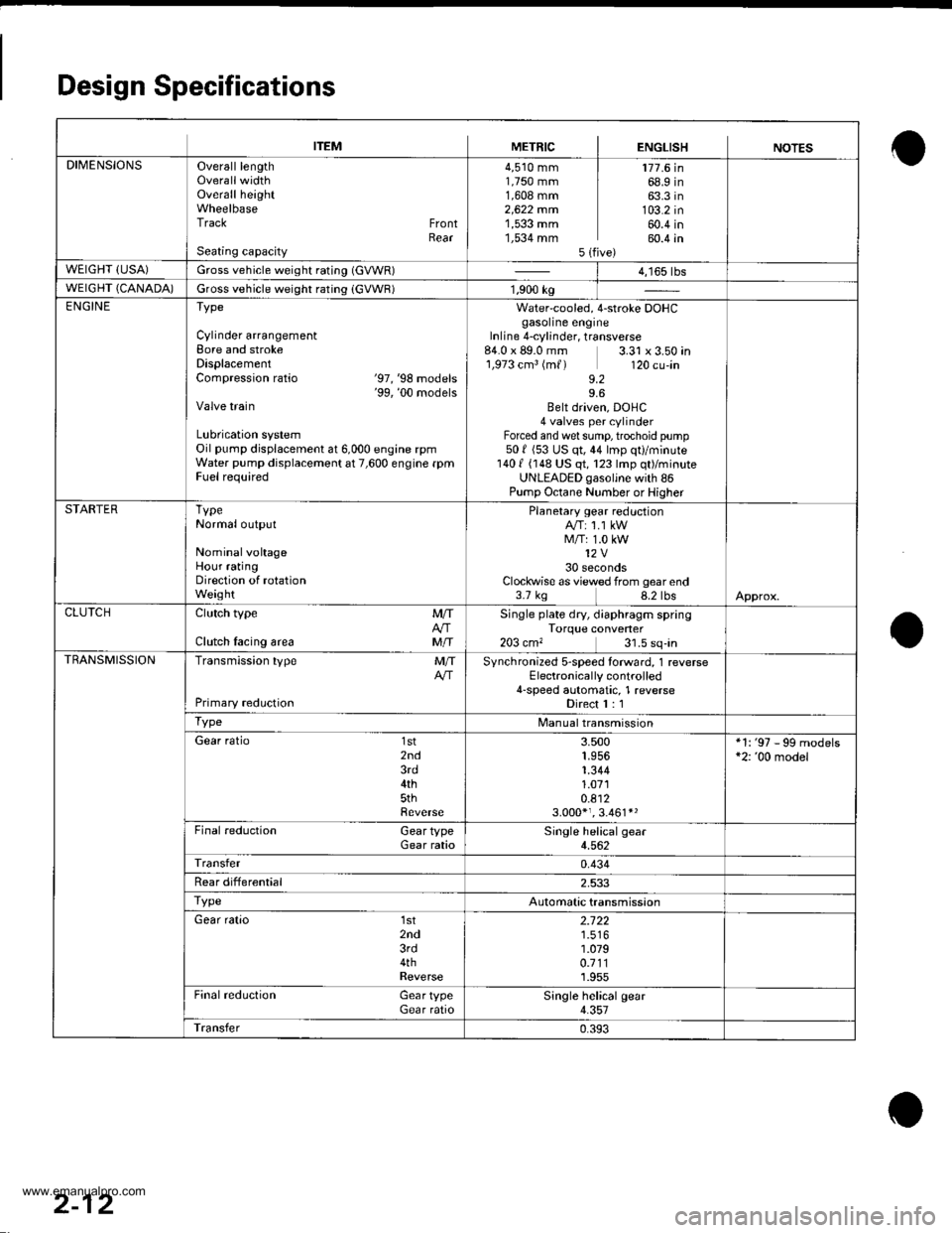
Design Specifications
ITEMMETRICENGLISHNOTES
DIMENSIONSOverall lengthOverallwidthOverall heightWheelbaseTrack FrontRearSeating capacity
4,510 mm1,750 mm1,608 mm2,622 mrn1,533 mm1,534 mm5lf
177.6 in68.9 in63.3 in103.2 in60.4 in60.4 in
WEIGHT (USA)Gross vehicle weight rating (GVWR)| 4,165 tbs
WEIGHT (CANADA)Gross vehicle weight rating (GVWR)1,900 kg
ENGINEType
Cylinder arrangementBore and strokeDisplacementCompression ratio '97,'98 mooers'99, '00 modelsValve train
Lubrication systemOil pump displacement at 6,000 engine rpmWater pump displacement at 7,600 engine rpmFuel required
Water-cooled, 4-stroke DOHCgasoline engineInline 4-cylinder, transverse84.0 x 89.0 mm.1,973 cm3 (m{)
9.2
3.31 x 3.50 in120 cu-in
9.6Belt driven, DOHC4 valves per cylinderForced and wet sump, trochoid pump501 (53 US qt,44 lmp qt)/minute1401 (148 US qt, 123 lmp qt)/minuteUNLEADED gasoljne with 86Pump Octane Number or Higher
STARTERTypeNormal output
NominalvohageHour ratingDirection of rotationWeight
Planetary gear reductionA/T: 1.1 kWM/T: 1.0 kW12V30 secondsClockwise as viewed from gear end3.7 kg 8.2 lbsApprox.
CLUTCHClutch type
Clutch lacing area
MIT
MIT
Single plate dry, diaphragm springTorque converter203 cm, 31.5 sq-in
TRANSMISSIONTransmission type
Primary redLrction
MITSynchronized s-speed torward, 1 reverseElectronically controlled4-speed automatic, 1 reverseDirect I : 1
TypeManualtransmission
Gear ratio 1st2nd3rd4th5thReverse
3.5001.9561.3441.0710.8123.000*,. 3.461*'
*1: '97 - 99 models*2: '00 model
Final reduction Gear typeGear rataoSingle helical gear4.562
Transfer0.434
Rear differential2.533
TypeAutomatic transmission
Gear ratio 1st2nd3rd4thReverse
2.722
1.0790.7111.955
Final reduction Gear typeGear ratioSingle helical gear4.357
Transfer0.393
2-12
www.emanualpro.com
Page 92 of 1395
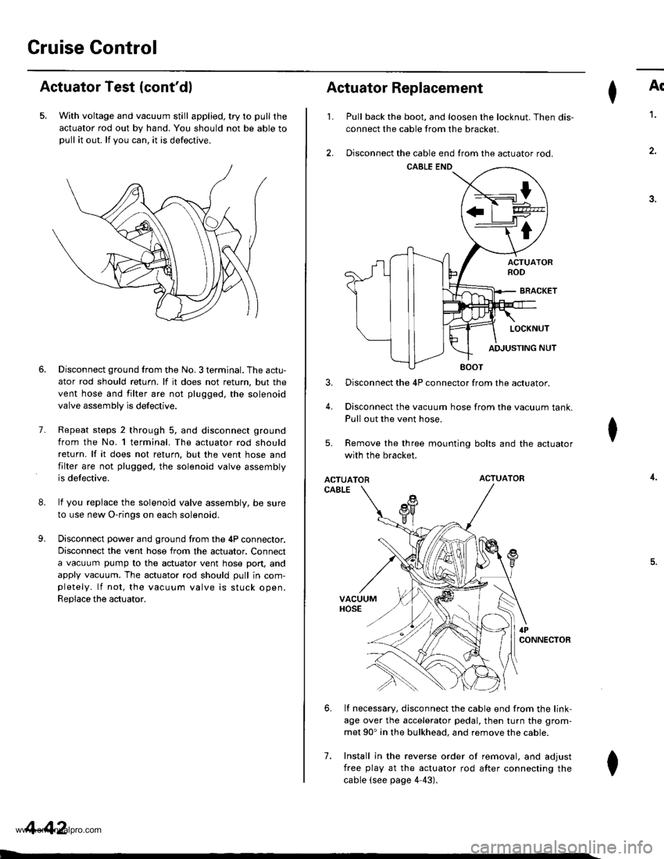
Cruise Gontrol
Actuator Test (cont'dl
5. With voltage and vacuum still applied, try to pull the
actuator rod out by hand. You should not be able topull it out. lf you can. it is defectrve.
8.
9.
7.
Disconnect ground from the No. 3 terminal. The actu-
ator rod should return. lf it does not return, but the
vent hose and filter are not plugged, the solenoid
valve assembly is defective.
Repeat steps 2 through 5. and disconnect ground
from the No. l terminal. The actuator rod should
return. lf it does not return, but the vent hose and
filter are not plugged, the solenoid valve assembly
is defective.
lf you replace the solenoid valve assembly, be sure
to use new O-rings on each solenoid.
Disconnect power and ground from the 4P connector.
Disconnect the vent hose from the actuator. Connect
a vacuum pump to the actuator vent hose port, and
apply vacuum. The actuator rod should pull in com-pletely. lf not, the vacuum valve is stuck open.
Replace the actuator,
4-42
I
't.
Actuator Replacement
3.
4.
7.
Ar
Pull back the boot. and loosen the locknut. Then dis-
connect the cable from the bracket.
Disconnect the cable end from the actuator rod.
1.
4.
.J.
Disconnect the 4P connector from the actuator.
Disconnect the vacuum hose from the vacuum tank.
Pull out the vent hose.
Remove the three mounting bolts and the actuator
with the bracket.
ACTUATORACTUATOR
CABLE
lf necessary, disconnect the cable end from the link-
age over the accelerator pedal, then turn the grom-
met 90' in the bulkhead. and remove the cable.
Install in the reverse order of removal, and adjust
free play at the actuator rod after connecting the
cable (see page 4-43).
I
6.
I
www.emanualpro.com
Page 94 of 1395
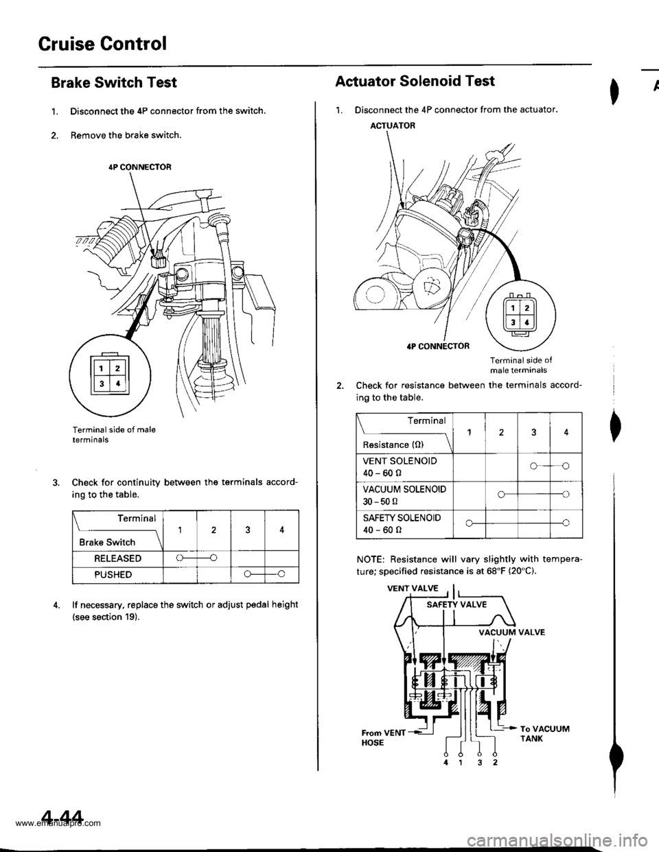
Cruise Control
Brake Switch Test
1. Disconnect the 4P connector from the switch,
2. Remove the brake switch.
Terminal side of maletermtnals
Check for continuity between the terminals accord-
ing to the table.
lf necessary, replace the switch or adjust pedal height
(see section 19).
{P CONNECTOR
Terminal
;;;;-t
15
RELEASEDO----o
PUSHEDo--o
4-44
ACTUATOR
Actuator Solenoid Test
1. Disconnect the 4P connector from the actuator.
Terminalside ofmale terminals
Check for resistance between the terminals accord-
ing to the table.
NOTE: Resistance will vary slightly with tempera-
ture; specified resistance is at 68"F (20"C).
VALVE
I
I
I
To VACUUMTANK
Terminal
il',",""*(t)
_\13
VENT SOLENOID
40-600o--o
VACUUM SOLENOIDo---o
30-500
SAFEW SOLENOID
40-600o----o
VACUUM
www.emanualpro.com
Page 95 of 1395
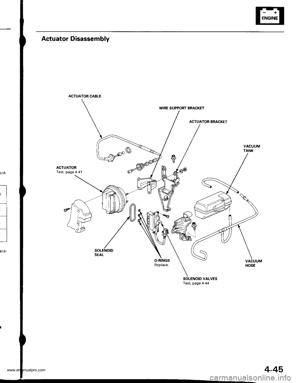
Actuator Disassembly
ACTUATOR ERACKET
VALVESTest, page 4-44
VACUUMTANK
)rd'
!
l
l
ACTUATOR CABLE
4-45
www.emanualpro.com