crank pulley removal HONDA CR-V 1999 RD1-RD3 / 1.G Workshop Manual
[x] Cancel search | Manufacturer: HONDA, Model Year: 1999, Model line: CR-V, Model: HONDA CR-V 1999 RD1-RD3 / 1.GPages: 1395, PDF Size: 35.62 MB
Page 114 of 1395
Cylinder Head/Valve Train
Speciaf Tools .............6-2
Valve Clearance
Adiustment ............6-3
Valve Seals
Replacement (cylinder head
removal not requiredl ................. 6-5
Crankshaft Pulley and Pulley Bolt
Replacement .........6-7
Timing Belt
I llustrated lndex ............................... 6-8
Inspection ............., 6-9
Tension Adjustment ........................ 6-9
Removal ...........,..... 6-10
lnstallation .............6-11
Crankshaft Speed Fluctuation (CKFI
Sensor
Replacement .........6-13
Cylinder Head
lllustrated lndex ............................... 6-14
Removal .................6-16
Warpage ................6-27
lnstallation ............. 6-30
Camshafts
lnspection ..............6-22
Valves, Valve Springs and Valve Seals
Removal ................, 6-23
lnstallation ............. 6-29
Valve Guides
Valve Movement ............,,,,.,............ 6-25
Replacement .........6-25
Reaming .................6-27
Valve Seats
Reconditioning ......6-28
www.emanualpro.com
Page 118 of 1395
Valve Seals
Replacement (cylinder head removal not required)
The procedure shown below applies when using the in-
car valve spring compressor (Snap-on YA8845 with
YA8845-2A 7/8" auachment). Use approved eye protec-
tion.
1. Turn the crankshaft so that the No. 1 and the No. 4
pistons are at top dead center (TDC).
2. Remove the cylinder head cover.
3. Remove the distributor.
4. Loosen and disconnect the timing belt from the
camshaft pulleys.
5. Remove the camshaft holder bolts. then remove the
camshaft holders, the camshafts and rocker arms.
lntake Valve Seals
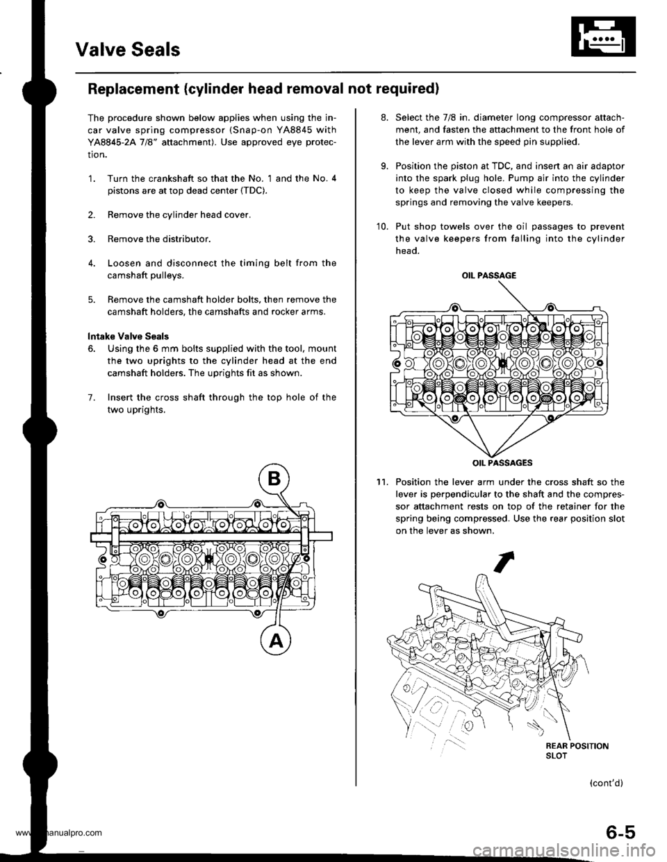
6. Using the 6 mm bolts supplied with the tool, mount
the two uprights to the cylinder head at the end
camshaft holders. The uprights fit as shown.
7. Insert the cross shaft through the top hole of the
two uprights,
at.
9.
Select the 7/8 in. diameter long compressor attach-
ment, and fasten the attachment to the front hole of
the lever arm with the speed pin supplied.
Position the piston at TDC, and insen an air adaptor
into the spark plug hole. Pump air into the cylinder
to keep the valve closed while compressing the
springs and removing the valve keepers.
10. Put shop towels over the oil passages to prevent
the valve keepers from falling into the cylinder
head.
Position the lever arm under the cross shaft so the
lever is perpendicular to the shaft and the compres-
sor attachment rests on top of the retainer for the
spring being compressed. Use the rear position slot
on the lever as shown,
't1.
OIL PASSAGE
OIL PASSAGES
(cont'd)
6-5
www.emanualpro.com
Page 121 of 1395
Timing Belt
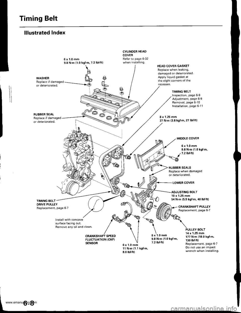
lllustrated Index
Cl
k6
CYLINDER HEADCOVERRefer to page 6-32when installing.
6x1.0mfi11 N.m {1.1 kgtm,8.0 rbtft)
HEAD COVER GASKETReplace when leaking,damaged or deteriorated.Apply liquid gasket atthe eight corners of theWASHERReplace if damagedor deteriorated,
RUEBER SEALReplace il damagedot detetiorated.
kgf.m,
\@
7.2 tbtft)
TIMING BELTInspection, page 6-9Adjustment, page 6-9Removal, page 6-10Installation, page 6-1 1
8 x 1.25 mm37 N.m (3.8 kst.m,27 lbf ftl
MIDOLE COVER
6x1.0mm9.8 N.m {1.0 kgf.m,1.2lbt.ftl
RUBBER SEALSReplace when damagedor deteriorated,
LOWER COVER
TIMING BELTORIVE PULLEYReplacement, page 6'7
ADJUSTING BOLT10 x 1.25 mm54 N.m (5.5 kgl.m, 40 lbf.ft)
CNANKSHAFT PULLEYneplacement, page 6-7
lnstall with concavesurface facing out,Remove any oal and clean,BOLT
CRANKSHAFT SPEEOFLUCTUATION ICKF}SENSOR
6x1.0mm9.8Nm(1.0kgl.m,7.2 tbl.ft)
14 x 1.25 mm177 N.m (18.0 kgf'm,130 tbf.fr)Replacement, Page 6-7Do not use an impactwrench when installing.
www.emanualpro.com
Page 123 of 1395
Timing Belt
Removal
Replace the timing belt at 105,000 miles (168,000 km)
according to the maintenance schedule {normal condi-
tions/severe conditions). lf the vehicle is regularly driven
in either of the following conditions, replace the timing
belt at 60,000 miles (U.S.A.l 100.000 km (Canada).
- ln very high temperatures (over 110'F, 43"C).- In very low temperatures (under -20"F. -29"C).
Turn the crankshaft pu\ley so the No. 1 piston is at
top dead center (TDC).
Remove the guard bar and splash shield (see page
5-7 ).
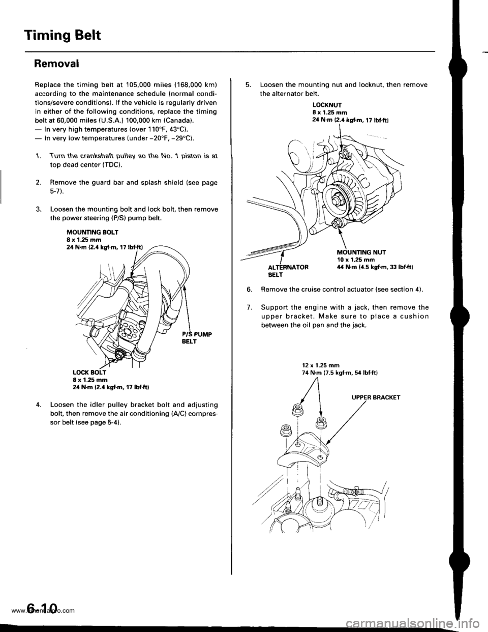
Loosen the mounting bolt and lock bolt. then remove
the power steering (P/S) pump belt.
MOUNNNG BOLT8 x 1.25 rnm
1.
2.
,l
4. Loosen the idler pulley bracket bolt and adjusting
bolt, then remove the air conditioning (lVC) compres
sor belt (see page 5-4).
6-10
24 N.m {2.4 kgt.m, 17 lbf.ftl
24 N.m 12.4 kgf.m, lt lbf.ftl
5. Loosen the mounting nut and locknut, then remove
the altefnator belt.
LOCKNUTI x 1.25 mm2a N.m 12.4 kgt m, 17 lblftl
6.
10 x 1,25 mm4,1 N.m (,1.5 kgt m, 33 lbtftl
Remove the cruise control actuator (see section 4).
Support the engine with a jack, then remove the
upper bracket. Make sure to place a cushion
between the oil Dan and the iack.
12 x 1.25 mm74 N.m (7.5 kgf m, 54 lbtftl
7.
BRACKET
AELT
www.emanualpro.com
Page 124 of 1395
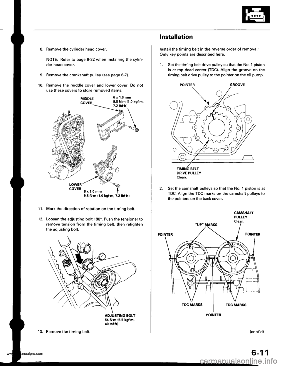
8. Remove the cylinder head cover.
NOTE: Refer to page 6-32 when installing the cylin-
der head cover.
Remove the crankshaft pulley (see page 6-7).
Remove the middle cover and lower cover. Do not
use these covers to store removed items.
9.
10.
11.
MTDDLE 6x1.0mm
COVER 9.8 N.m {1.0 kgt m,
LOWERCOVER
9.8 N.m (1.0 kgt.m, 7.2 lbf.ftl
Mark the direction of rotation on the timing belt.
Loosen the adjusting bolt 180'. Push the tensioner to
remove tension from the timing belt, then retighten
the adiusting bolt.
AINUSTING BOLT54 N.m (5,5 kgt m,.(} tbf.rrl
12.
13. Remove the timing belt.
Installation
Install the timing belt in the reverse order of removal;
Only key points are described here,
1. Set the timing belt drive pulley so that the No. 1 piston
is at top dead center (TDC). Align the groove on the
timing belt drive pulley to the pointer on the oil pump.
GROOVE
DRIVE PULLEYClean.
2. Set the camshaft pulleys so that the No. I piston is at
TDC. Align the TDC marks on the camshaft pulleys to
the pointers on the back cover.
POINTER
CAMSHAFTPULLEYClean.
POINTER
r-t
(cont'd)
6-11
www.emanualpro.com
Page 126 of 1395
CKF Sensor
Replacement
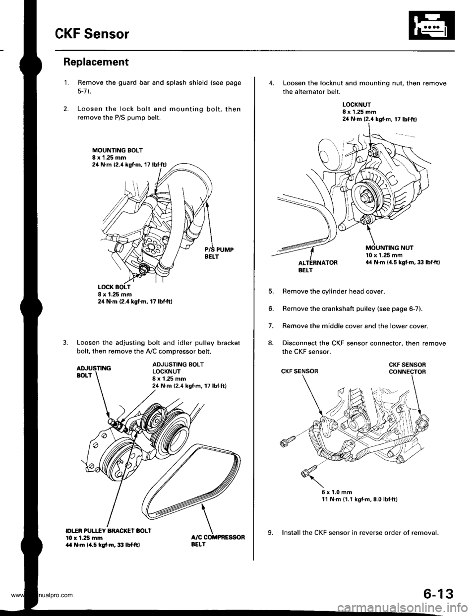
1.
|o|'ln PUUCY BMCKET SOLIl0 r 1.25 mm14 .m 14.5 kgl.m,3:' lbtftl
Remove the guard bar and splash shield (see page
5-7 t.
Loosen the lock bolt and mounting bolt, then
remove the P/S pump belt.
MOUNTING BOLT8 x 1.25 mm
PUMPBELT
Loosen the adjusting bolt and idler pulley bracket
bolt, then remove the Ay'C comDressor belt.
ADJUSTING BOLTLOCKNUT8 x 1.25 mm24 N.m {2.4 kgf.m, 17 lbf.ft)
24 N.m (2.{ kgf.m, 17 lbf.ttl
24 N.m 12.4 lgf.m, 17 lbl.ftl
4. Loosen the locknut and mounting nut, then remove
the alternator belt.
LOCKNUT8 x 1.25 mm24 N.m (2.4 kgl.m, 17 lbtftl
10 x 1 .25 mma4 N.m (4.5 kgt m, 33 lbtft)
E
6.
7.
aJ.
Remove the cylinder head cover.
Remove the crankshaft pulley (see page 6-7).
Remove the middle cover and the lower cover.
Disconnect the CKF sensor connector, then remove
the CKF sensor.
6x1.0mm11 N.m {1.r kgnm,8.0 lbfft)
9. Install the CKF sensor in reverse order of removal.
BELT
CKF SENSOR
6-13
www.emanualpro.com
Page 688 of 1395
Transmission
21.
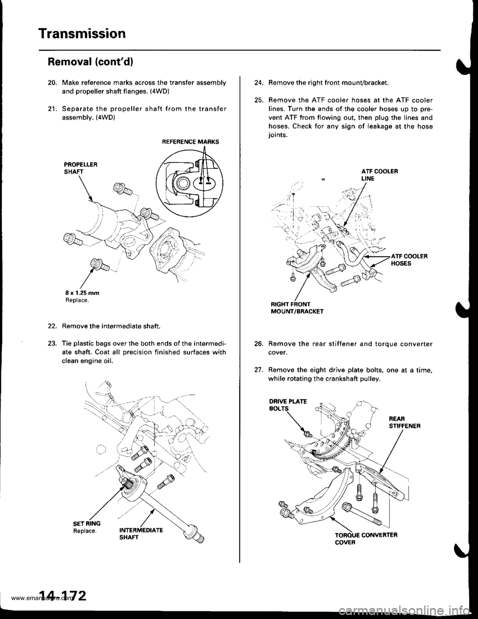
Removal (cont'dl
Make reference marks across the transfer assemblv
and propeller shaft flanges. (4WD)
Separate the propeller shaft from the transfer
assembly. (4WD)
I x 1.25 mmReplace.
Remove the intermediate shaft,
Tie plastic bags over the both ends of the intermedi-
ate shaft. Coat all precision finished surfaces with
clean engine oil.
22.
REFERENCE MARKS
14-172
24.Remove the right front mounvbracket.
Remove the ATF cooler hoses at the ATF cooler
lines. Turn the ends of the cooler hoses uo to ore-
vent ATF from flowing out, then plug the lines and
hoses. Check for any sign of leakage at the hose
ioints.
RIGHT FRONTMOUNT/BRACKET
Remove the rear stiffener and torque converter
cover.
Remove the eight drive plate bolts, one at a time.
while rotating the crankshaft pulley.
27.
COVER
DRIVE PLATE
www.emanualpro.com