high tension wire HONDA CR-V 1999 RD1-RD3 / 1.G Workshop Manual
[x] Cancel search | Manufacturer: HONDA, Model Year: 1999, Model line: CR-V, Model: HONDA CR-V 1999 RD1-RD3 / 1.GPages: 1395, PDF Size: 35.62 MB
Page 1188 of 1395

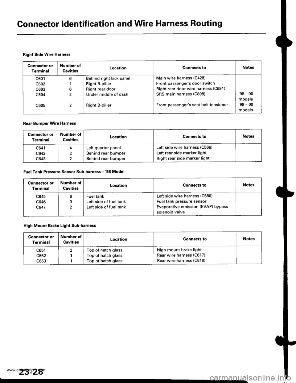
Gonnector ldentification and Wire Harness Routing
Right Side Wire Harness
Connec{or or
Tsrminal
Number of
CavitiesLocationConnests toNotes
c601
c602
c603
c604
6'1
2
2
Behind right kick panel
Right B-piller
Right rear door
Under middle of dash
Right B-piller
Main wire harness (C428)
Front passenger's door switch
Right rear door wire harness (C691)
SRS main harness {C808)
Front passenger's seat belt tensioner
'98 - 00
mooets'98 - 00
models
Rear Bumper Wire Harness
Connector ol
Terminal
Number ot
CavitiesLocationConnocts toNotes
c641
c642
c643
4
2
2
Left quarter panel
Behind rear bumper
Behind rear bumper
Left side wire harness (C566)
Left rear side marker light
Right rear side marker light
Fuel Tank Pressure Sensor Sub-harness - '98 Model
Connector or
Terminal
Number ot
CavitiesLocationConnects toNot63
c645
c646
c647
?
2
Fueltank
Left side of fuel tank
Left side of fuel tank
Left side wire harness (C580)
Fuel tank pressure sensor
Evaporative emission (EVAP) bypass
solenoid valve
High Mount Brake Light Sub-harnoss
Conneslor or
Terminal
Number of
CavitiesLocationConnec-ts toNotes
c651
c652
c653
2
1
1
Top of hatch glass
Top of hatch glass
Top of hatch glass
High mount brake light
Rear wire harness (C617)
Rear wire harness (C618)
23-28
www.emanualpro.com
Page 1323 of 1395

Troubleshooting
Self-diagnostic Procedures
The self-diagnostic function of the SRS system allows it to locate the causes of system problems and to store this informa-
tion in memory, For easier troubleshooting, this data can be retrieved via a data link circuit.
. When you turn the ignition switch ON (ll). the SRS indicator will come on. lf it goes off after six seconds, the system is
normal.
. lf there is 8n abnormality, the system locates and defines the problem. stores this information in memory, and turns
the SRS indicator light on. The data will remain in the memory even when the ignition switch is turned off or if the bat-
terv is disconnected.
. When you connect the SCS service connector to the service check connector (2P), and turn the ignition switch ON (ll),
the SRS indicator light will indicate the diagnostic trouble code (DTC) by the number of blinks.
. After reading and recording the DTC, proceed with the troubleshooting forthis code.
Precsutions
. Use only a digital multimeter to check the system. lf it's not a Honda multimeter. make sure its output is 10 mA (0.01 A)
or less when switched to the smallest value in the ohmmeter range. A tester with a higher output could damage the
airbag circuit or cause accidental airbag deployment and possible injury.
. Whenever the ignition switch isON (ll). or has been turned OFF for less than three minutes, be careful nottobumpthe
SRS unit; the airbags could accidentally deploy and cause damage or injuries.
. Before you remove the SRS main harness, disconnect the airbag and tensioner connectors (see page 24-23).
. Make sure the battery is sufficiently charged (see section 23). lf the battery is dead or low, measuring values won't be
correct.
. Do not touch a tester probe to the terminals in the SRS unit or harness connectors, and do not connect the terminals
with a jumper wire. Use only the backprobe set and the SCS service connector.
For backprobing spring-loaded lock type con nectors, .efet to page 24-22.
Reading the DTC
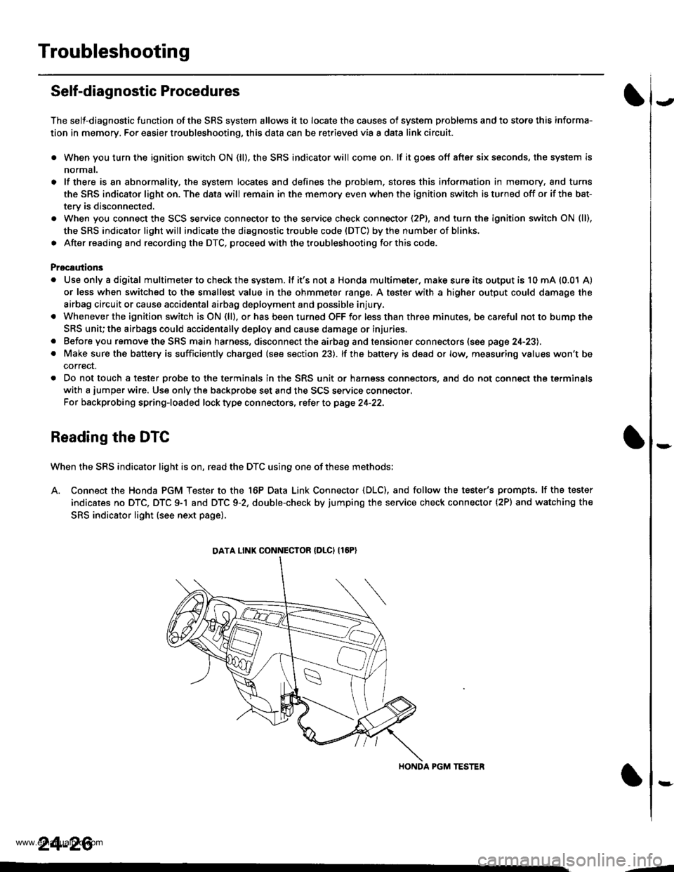
When the SRS indicator light is on, read the DTC using one of these methods;
A. Connect the Honda PGM Tester to the 16P Data Link Connector {DLC), and follow the tester's prompts. lf the tester
indicates no DTC, DTC 9-1 and DTC 9-2, double-check by jumping the service check connector (2P) and watching the
SRS indicator light (see next page).
HONDA PGM TESTER
DATA LINK CONNECIOR {DLCI {16P)
24-26
,1
www.emanualpro.com
Page 1395 of 1395

Airbag/Seat Belt Tensioner
1.
Disposal (cont'dl
Connect a 12 volt battery to the tool'
. It the green light on the tool comes on, the air-
bag igniter circuit is defective and cannot deploy
the airbag. Go to Damaged Airbag Special
Procedure.
.lftheredlightonthetool comes on, the airbag is
ready to be deployed.
Push the tool's deployment switch. The airbag
should deploy (deployment is both highly audible
and visible; a loud noise and rapid inflation of the
bag, followed by slow deflation).
. lf the airbags deploy and the green light on the
tool comes on, continue with this procedure.
. lf an airbag doesn't deploy, yet the green light
comes ON, its igniter is defective. Go to Dam-
aged Airbag Special Procedure.
. During deployment, the airbag can become hot
enough to burn you, Wait thirty minutes after
deployment before touching the airbag.
Dispose of the complete airbag. No part of it can be
reused. Place it in a sturdy plastic bag, and seal it
securety.
CAUTION:
. Wear a faco shield and gloves when handling a
deployed airbag.
. Wash your hands and rinse them well with
water after handling a deployed airbag.
24-98
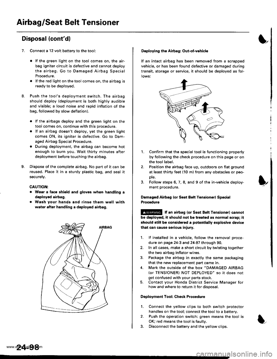
Deploying tho Airbag: Out-ot.vohicle
lf an intact airbag has been removed from a scrapped
vehicle, or has been found defective or damagsd during
transit. storage or seryice, it should be deployed as fol-
lows:
'L Confirm that the special tool is functioning properly
by following the check procedure on this page or on
the tool label.
2. Position the airbag face up, outdoors on flat ground
at least thirty feet (10 m) from any obstacles or peo-
Dte,
3. Follow steps 6, 7, 8. and 9 of the in-vehicle deploy-
ment proceoure.
Dlmaged Airbsg {or Seat Beh Ten3ion6r} Sp6cial
Procgdure
!@ r an airbag {or seat Beh rensioner} cannol
be doployod, it should not be treated as normal scrap; it
should still be considered a pot€ntially explosive device
lhat can cause serious iniury.
1. lf installed in a vehicle. follow the removal proce-
dure on page 24-3 and 24-87 through 90.
2. In all cases, make a short circuit by twisting together
the two airbag inflator wires.
3. Package the airbag in exactly the same packaging
that the new reDlacement Dart came in.
4. Mark the outside of the box "DAMAGED AIRBAG
{or TENSIONER) NOT DEPLOYED" so it does not
get confused with your parts stock.5. Contact your Honda District Service Manager forhow and where to return it for disposal.
Deployment Tool: Check Procedure
Connect the yellow clips to both switch protector
handles on the tool; connect the tool to a battery.
Push the operation switch: green means the tool is
OK: red means the tool is faultv.
Disconnect the baftery and the yellow clips.
I
t
l.
www.emanualpro.com