honda city HONDA CR-V 1999 RD1-RD3 / 1.G Workshop Manual
[x] Cancel search | Manufacturer: HONDA, Model Year: 1999, Model line: CR-V, Model: HONDA CR-V 1999 RD1-RD3 / 1.GPages: 1395, PDF Size: 35.62 MB
Page 17 of 1395
![HONDA CR-V 1999 RD1-RD3 / 1.G Workshop Manual
Under-hood Emissions Control Label
Emission Group ldentification
(1997 modell
Example:
VACUUM HOSE ROUTING DIAGRAM
LOADED IM TEST]NG OF PERMANENT fOUB WHEEL OSVE OR TRACT ON CONTROLEOLJIPPEDVEHTCLES](/img/13/5778/w960_5778-16.png "HONDA CR-V 1999 RD1-RD3 / 1.G Workshop Manual
Under-hood Emissions Control Label
Emission Group ldentification
(1997 modell
Example:
VACUUM HOSE ROUTING DIAGRAM
LOADED IM TEST]NG OF PERMANENT fOUB WHEEL OSVE OR TRACT ON CONTROLEOLJIPPEDVEHTCLES")
Under-hood Emissions Control Label
Emission Group ldentification
(1997 modell
Example:
VACUUM HOSE ROUTING DIAGRAM
LOADED IM TEST]NG OF PERMANENT fOUB WHEEL OSVE OR TRACT ON CONTROL'EOLJIPPEDVEHTCLES MUST BE CONDUCTED ON A IOUR WHEEL DR VE SPEEO SYNCHRON ZED
ANON LOADEDTESTPBO(EOUBEMUSIBEPERFORMEO
50ST (50 Statesl:
THIS VEHICLE CONFOBMS TO U.S. EPA AND STATE OF
CALIFORNIA REGULATIONS APPLICABLE TO 1997
MODEL YEAR NEW LIGHT DUTY TRUCKS.
49ST {49 Statos/Federall:
THIS VEHICLE CONFORMS TO U.S. EPA REGULATIONS
APPLICABLE TO 1997 IVIODEL YEAR NEW LIGHT DUTY
TRUCKS.
CAL (Calitornial:
THIS VEHICLE CONFORMS TO U.S. EPA AND STATE OF
CALIFORN IA REGULATIONS APPLICABLE TO '1997
MODEL YEAR NEW TLEV LIGHT DUTY TRUCKS
PROVIDED THAT THIS VEHICLE IS ONLY INTRODUCED
INTO COMMERCE FOR SALE IN THE STATE OF
CALIFORNIA.
Ii/PORTANT VEHICLE INFORIMATIONENGINE FAMILY VHN2 OIJCrcKDISPIACEMENT'2 OLITEREVAPORAT VE f AM]LY VNNl0778YMBP
CATALYSTREfERTOSEBVICEMANUALfORAODITIONAL NFORMATON.TUNT I-]P CONDITIONSENGINE AT NORI\,!AL OPERATNG TEMPERATURE,ALLACCESSOR ES TL]RNED OFF COOLING FAN OIFTRANSM1SSION NNEUTRALNO OTHEB ADJUSTMENIS NEEDED
ap' | \6( Zror '. ND \. 61F L r
TNIS VENICLE CONFORMS TO U.S EPA REGUI.ATIONSAPPI CASLE TO I99] MODET YEAR N€W L GNI DUTY TRACKS
@
Engine Family: vHN2.o l JGKE
Engine and Evaporative Families
T_fT
Model Year I Iv:1s97 | LManufaqturer iHN: Honda I
Displacement
Class
1: Light Duty Vehicle
Fuol Systom ,nd Numb€r of valves
J: Electronic Sequential Multiport
Injection (three or more valves per
cylinder)
Fuel Type
G: Gasoline
Standard
F: 49 or 50 States Tier 1
K: 49 or 50 States Tier 1
1: California Tier 1
2: California TLEV
3: California LEV
4: California ULEV
"r0", "*,
T|
V: 1997
Manufacturer
HN: Honda
Catalyst
E, F, G, H: Three Way Catalyst
OBD
K - T: OBD Equipped
Evaporative Family:
Storago System
1: Canister
Canistor Working Capacity (gramsl
Canister Conf igulation
A: Plastic Housing (Closed Bottom)
B: Plastic Housing (OPen Bottom)
Fusl System
Y: Fuel Injection
FuelTank
M: Metal
Standard
A: Current Evap
B: Enhanced Evap
Wild C.rd
VHNlOTTBYMBP
1-1 5
www.emanualpro.com
Page 18 of 1395
Under-hood Emissions Control Label
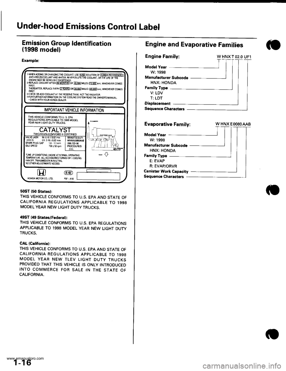
Emission Group ldentification
(1998 modell
Example:
50ST {50 States}:
THIS VEHICLE CONFORMS TO U.S. EPA AND STATE OFCALIFORNIA REGULATIONS APPLICABLE TO 1998MODEL YEAR NEW LIGHT DUTY TRUCKS,
/$ST (itg Statos/Fodsrsll:
THIS VEHICLE CONFORMS TO U.S. EPA REGULATIONSAPPLICABLE TO 1998 MODEL YEAR NEW LIGHT DUTYTRUCKS.
CAL {California}:
THIS VEHICLE CONFORMS TO U.S. EPA AND STATE OFCALIFORNIA REGULATTONS APPLICABLE TO 1998MODEL YEAR NEW TLEV LIGHT DUTY TRUCKSPROVIDED THAT THIS VEHICLE IS ONLY INTRODUCEDINTO COMMERCE FOR SALE IN THE STATE OFCALIFORNIA.
DwlF AIo|NG oB cha\Gtftc I + coot r
-s€ msoru1or or FoNoA-IEaoTTxD-ibl1'v! Lrff EzEcoo-aN' a\D wATfB. M w r or_ut-ir coolqNt, oR-l;ir,FEaFEf-ENGINE MAY BE SEflIOUSLYSIONTENEO.DSEPLACI CoOTANT AnEs 85 itNlgsloF @ MILIS l@0 rnl, wHrcHEvEs coMEs
TNEREAFT€R, REPLACE EvEny fmAFSl m m M[Es i@ kml, wHcHrvEB coMEs
DCHEC(ONADOCOOLqNTATTHE RSSEFVETANX. NOTTHE iAD]ATOR.DFOR FUFTNEfr INFO8MATION ON IN€ COOT]NC SYSIEM NEAD THE OWNEN'S MANUAL,. CHECK W|TH YOUR NONDA OEALEF.
@GD
IMPORTANT VEHICLE INFORMATION
THIS VEHICLE CONFOEMS TO I], S. EPAFEGIJLAIIONSAPPLICASLE TO 1993 MOOELY€AF NEW LIGHT DUIYTNUCXS.
CATALYSTrwqHozst2l/sFt/osD l cERI|FtEOvAlvttAsH lrr0.l010.02nmicolo) EX:01310.02mmSPAS( PIUG GAP I.O IINMlDLl SPTED 750 I 50 rym686,13G96PROCEOURESI2.0 L
TlNt UPCoND/ToNS: ENGINE AT NOiMIEMPETAIURT,ALLACCESSORIESTUNNIfAN OFf. TRAI1SMISSON IN NEUTMINO OIIIER AOJUSTI\TFIIS IIEEOED.
1-16
Engine and Evaporative Families
Engine Family:W HNX T O2.O UF1
Mod€l Year
W: 1998
Manufacturer Subcods
HNX: HONDA
Family Typo
V: LDV
T: LDT
Displacomsnt
Soqu€nco Characiors
Evaporative Fami
Family:
Model Yeat
W:1998
Manufastu16r Subcode
HNX: HONDA
Family Type
E: EVAP
R; EVAP/ORVR
Canister Work Capacity
Sgquonco Charaqtsrs
W HNX EOOSOAAB
www.emanualpro.com
Page 19 of 1395
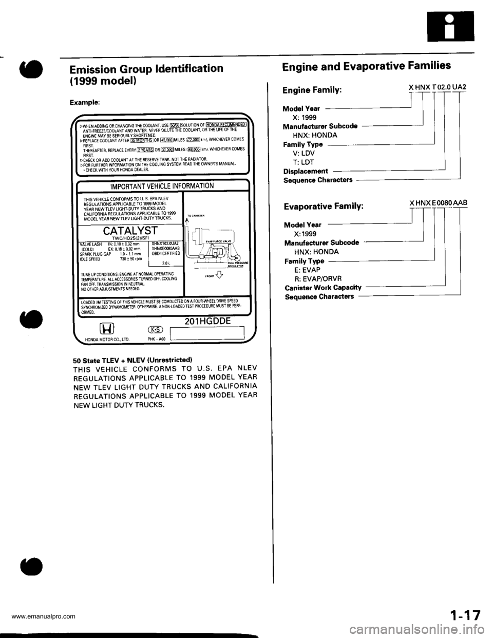
Emission Group ldentification
(1999 model)
Example:
50 state TLEV + NLEV {Unrestricted}
THIS VEHICLE CONFORMS TO U.S. EPA NLEV
REGULATIONS APPLICABLE TO 1999 MODEL YEAR
NEW TLEV LIGHT DUTY TRUCKS ANO CALIFORNIA
REGULATIONS APPLICABLE TO 1999 MODEL YEAR
NEW LIGHT DUTY TRUCKS.
'.WNEN AOO NG OR CNANGINC THE COOLANT. USE @SOLU I ON Of FONOA U-ECo-q.NOEDImcrtniuvcoourr mo wlttt NEVEF oILLJTE THE CooLANT,0RTHE LIFE 0F TNE
"Eifil:$o""niii?i,THffi ffi'"R @ M LEs lmo rhl, wNrcHEVEn coMEs
i'lrt^t orrrr, ^,r*a, rurr"* os @ M LEs 1@ kmr wNICHEVER coMEs
}CNECK OR ADD COOLANT AT THE RESER!'E TAN( NOT IHE NADIATOSDFOfi fWTHEF NFORMATION ON THE COOL NC SYSTEM READ THE OWNER'S MANUAL'' CHECK WIIH YOUS HONOA OEALER.
GD
IMPORTANT VEHICLE INFORMATION
THIS VEHICLE CONFOAMSTOU. S EPA NLEVFEGULANONS APPLICCBLI TO 1999 MOD€LYEA8 NEW TIEV LIGHT DUTY ]nUCKS ANDCALIFORNIA REGULATIONS APPLICASLE IO 19S9MOOEL YEAR NEW TLEV LIGHT DUTY IFIJCKS,,|F --'-
Ll: .-.-,1
I rFrll\=#_H*
CATALYST
VALVE IASN lN:010r0.02 mmlCoLDj EX 0131002 mmSPA8K PLUG GAP 10- l l nmIDLE SPEED 130 t 5{ rPmOBDIICERT]ATD
201
TUNE I]PCONDIIIONS INGINEAT NOBTEI\'PERATUR€ ATL ACCESSOS ES TLJRNFAN OFf IRANSMSSION N NEL]TMLNO OINER ADJUSTMTNTS NEEOEO.
JL
Iooro nr tist rc orn svtncrE MUsT BE coMoufitooNArounwNEElDslvE SPEEDiitriunor mo ovuvo uenn orr Enw sE a NoN.loaDE D rEsr PRoCE ouRE MU sT 8E Pf Rr-
Engine and Evaporative Families
Engine Family:X HNX T02,O UA2
Model Year
X:1999
Manutao{urer Subcode
HNX: HONDA
Family Type
V: LDV
T: LDT
Displacoment
Saquence Charactors
Evaporative Family:X HNX EOO8OAAB
Model Yoal
X:1999
Manutacturar Subcode
HNX: HONDA
Family Typo
E: EVAP
R: EVAP/ORVR
Canbter Work Capacity
S€quonce Chartsters
1-17
www.emanualpro.com
Page 20 of 1395
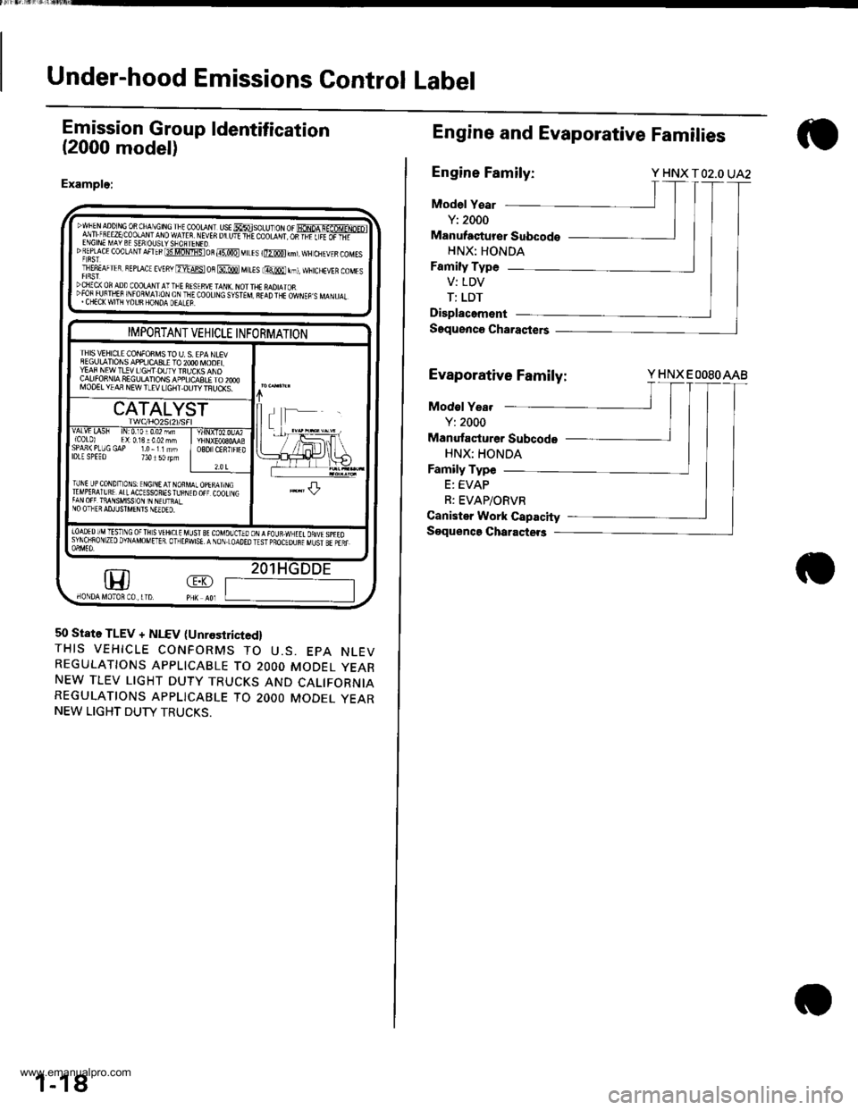
Under-hood Emissions Control Label
Emission Group ldentification
(2000 model)
Example:
DWFEN aDD r,tc 0R ChA\CtN! rlt cooraN. ust MsoLU- oN or fioNpA q-af6MrNp-ol
lfi ;!,."5:P!$t:1t9ffilf 1
vEn u u'r +-E coo|-d',r os-Fiiiiifi-'DREpf cE coolaNrAFTEBt3tlomistoR@MtLEs r@km),wH ctlEvrscoMEsT|E8EAFTER, BEprAcE EVEny ErdFst oB @ MttEs lmr,t, ffitcHEVER coMEsDCIIICX OF ADD COOLA I I'-FE AISIRVI TAI{I\. NOI THE MDIAIOR":3lliJ#fl "lj,9lx6L;T&Iji(0or|]\G s,5TEM 8r!D TrE owrEp s MA\u.r.
m
IMPORTANT VEHICLE INFORMATION
IHIS \/IHICLE CONFONMS TO U. S. EPA NLEVSEGULATIONS APPIJCq3LE TO 2OOO IVOOELYEAF NEW T!!V LIGHT DUTY TBUCKS ANDCALIFONNIA SEGULATIONS APPLICASLE TO 2OOOMOO€L YIAA NEW TLEV LIGHT.OUTY TFIJCKS.
CATALYST
vALvt LA5h tN:0,10r0.02 mm{C0t0l El:0.13!002 mhSPAn(PLUGGAP 1.0-11mmlDlE SPEEo 734150lpmO8O CENTFIED
?.0 t
TUNI UP CoNDIToNS: ENGINE AT NORMTTMPERAIURE ATLACCESSORIES fu BNITAN OFF TiANSMISS ON IN N€UTRALNO OTHER AD.ILJSTMENIS NEEDEO.
.l-L
|oAoEDr/MTESTNG oFTHsvtHrctE uLrst gt couolorooN,{raua.wxEtt onuspreosyNoiRoN zEo DvNAMoMETER. olrEiwsE. A NoN.LoAoEo rEsr pBocEounr uust sr pair
1
50 State TLEV + NLEV (Unrestricied,
THIS VEHICLE CONFORMS TO U.S. EPA NLEVREGULATIONS APPLICABLE TO 2OOO MODEL YEARNEW TLEV LIGHT DUTY TRUCKS AND CALIFORNIAREGULATIONS APPLICABLE TO 2OOO MODEL YEARNEW LIGHT DUTY TRUCKS.
1-18
Engine and Evaporative Families
Engine Family:Y HNX TO2.O UA2
Model Y€ar
Y: 2000
Manufaqturer Subcodo
HNX: HONDA
Family Type
V: LDV
T: LDT
Displacement
Saquenco Charasters
Evaporative Family:Y HNX EOOSOAAB
Modol Yea.
Y: 2000
Manufacturer Subcode
HNX: HONDA
Family Type
E: EVAP
R: EVAP/ORVR
Canister Work Capacity
Soquenca Charactet3
www.emanualpro.com
Page 35 of 1395
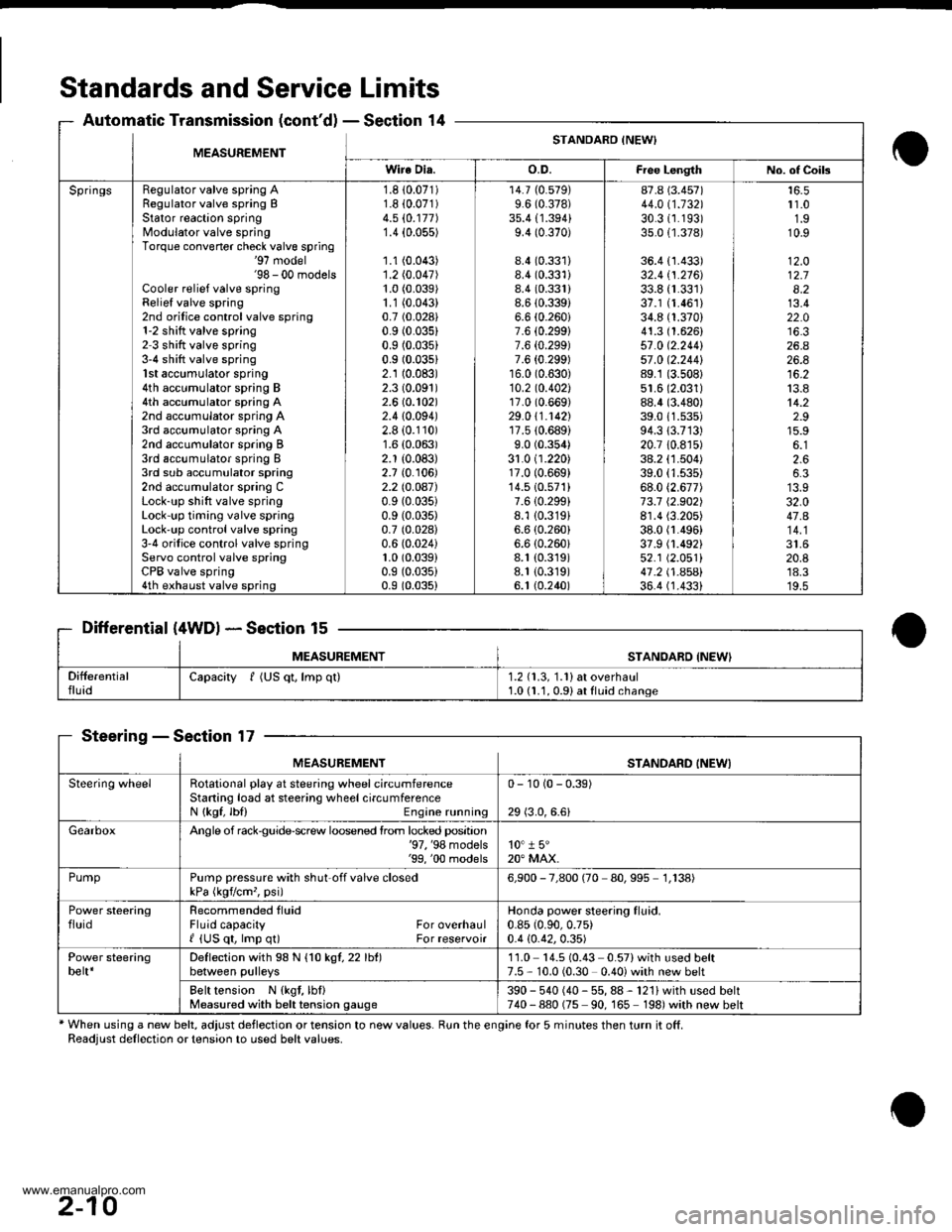
Standards and Service Limits
Automatic Transmission (cont'dl - Section 14
Differential (4WDl * Section 15
MEASUREMENTSTANOABD {NEW'
SteeringSection 17
* When using a new belt, adjust deflection or tension to new values. Run the engine for 5 minutes then turn it off.Readjust dellection or tension to used belt values.
MEASUREMENTSTANDARO INEWI
Wire Dia.o.D.Fiee LengthNo. of Coils
SpringsRegulator valve spring ARegulator valve spring BStator reaction springModulator valve springTorque convener check valve spring'97 model'98 - 00 modelsCooler relief valve springRelief valve spring2nd orilice control valve spring1-2 shitt valve spring2 3 shift valve spring3-4 shift valve spring1st accumulator spring4th accumulator spring B4th accumulator spring A2nd accumulator spring A3rd accumulator spring A2nd accumulator spring B3rd accumulator spring I3rd sub accumulator spring2nd accumulator spring CLock-up shift valve springLock-up timing valve springLock'up control valve spring3'4 orifice control valve springServo control valve springCPB valve spring4th exhaust valve spring
1.8 10.071)1.8 i0.071)4.5 (0.177)
1.4 {0.055)
1.1 (0.043)
1.2 (0.047)
1.0 (0.039)
1.1 (0.043)
0.7 (0.028)
0.9 (0.035)
0.9 (0.035)
0.9 (0.03s1
2.1 (0.083)
2.3 (0.091)
2.6 (0.102)
2.410.094)2.8 (0.110)
1.6 (0.063)
2.1 (0.083)
2.7 {0. r06)2.2lO.OA7)0.9 (0.035)
0.9 (0.035)
0.7 (0.028)
0.6 (0.024)
1.0 (0.039)
0.9 (0.035)
0.9 (0.035)
14.7 (0.579)
9.6 (0.378)
35.4 {1.394}9.4 (0.370)
8.4 (0.331)
8.4 (0.331)
8.4 (0.331)
8.6 (0.3391
6.6 (0.260i
7.6 {0.299}7.6 {0.299)7.6 {0.299)16.0 (0.630)
10.2 to.402l17.0 (0.669)
29.0 \1.1421'r7.510.689)
9.0 (0.354)
31.0 (1.220)17.0 (0.669)
14.510.571)7.610.299i8.1 {0.319}6.6 (0.260)
6.6 (0.260i
8.1 (0.319)
8.1 {0.319)6. t (0.240)
87.8 (3.457)
44.011.132130.31r.193)35.0 {1.378)
36.4 {1.433)32.4 tl.216J33.8 {r.331)37.1 (1.461)
34.8 (1.370)
41.3 (1.626)
57 .0 (2.2441
57 .0 12.244189.1 (3.508)
51.6 (2.031)
88.4 (3.480)
39.011.s35)94.313.713)20.7 10.8r5)38.2 (1.504)
39.0 (1.535)
68.0 (2.677)
73.7 12.902)8r.4 (3.205)
38.0 fl.496)37.9 (1.492)
52.1 (2.051)
41 .2 t .A5Al36.4 (1.4331
r 1.01.910.9
12.O12.78.213.422.0
26.426.8
13.814.22.915.9
2.66.3
32.047.A
20.8'18.3'19.5
Capacity f (US qt, lmp ql)1.2 (1.3, 1.1) at overhaul1.0 (1.1, 0.91 at fluid change
MEASUREMENTSTANDARD INEWI
Steering wheelRotational play at steering wheel circumferenceStaning load at steering wheelcircumferenceN {kgf, lbl) Engine running
0- 10 (0 - 0.39)
29 (3.0,6.6)
GearboxAngle of rack$uide-screw loosened lrom locked position'97, '98 models'99, '00 models10" 1 5"20" MAX.
PumpPump pressure with shut off valve closedkPa (kgvcm,, psi)6,900 - 7,800 (70 80,995 1,138)
Power steeringfluidRecommended tluidFluid capacity For overhaulI {US qt, lmp q0 For reservoir
Honda power steering fluid.0.85 (0.90,0.75)
0.4 {0.42,0.35)
Power steeringbelt*Deflection with 98 N {1O kgl,22lht)between pulleys11.0 14.5 (0.43 0.57)with used belt7.5 - 10.0 (0.30 0.40) with new belt
Belt tension N {kgt, lbf}Measured with belt tension gauge390 - 540 (40 - 55, 88 - 121) with used belt740-880 (75 90, 165 198)with new belt
2-10
www.emanualpro.com
Page 194 of 1395
Radiator
Engine Coolant Refilling and Bleeding (cont'dl
Mix the recommended antifreeze with an equal
amount of water in a clean container.
NOTE:
. Always use Genuine Honda Antifreeze/Coolant.
Using a non-Honda coolant can result in corro-s\on, ca
sng t\e coo\
g sys\em \o ma\lunct\on
o. fail.
For best corrosion protection, the coolant con-
centration must be maintained year-round at50% minimum. Coolant concentrations less than
50% may not provide sufficient protection against
corrosion or freezing. Coolant concentrationsgreater than 60% will impair cooling efficiency
and are not recommended.
Do not use additional rust inhibitors or anti-rustproducts; they may not be compatible with the
coolant.
Engine Coolant Refill Capacity Iincluding 0.6 / 10.63US $, 0.53 lmp qtl for hoater and ressrvoirl:
A/T: 3.9 f {4.1 US $, 3.4 lmp qtl
M/T: 1.O t 14.2 US $, 3.5 lmp qrl
10-6
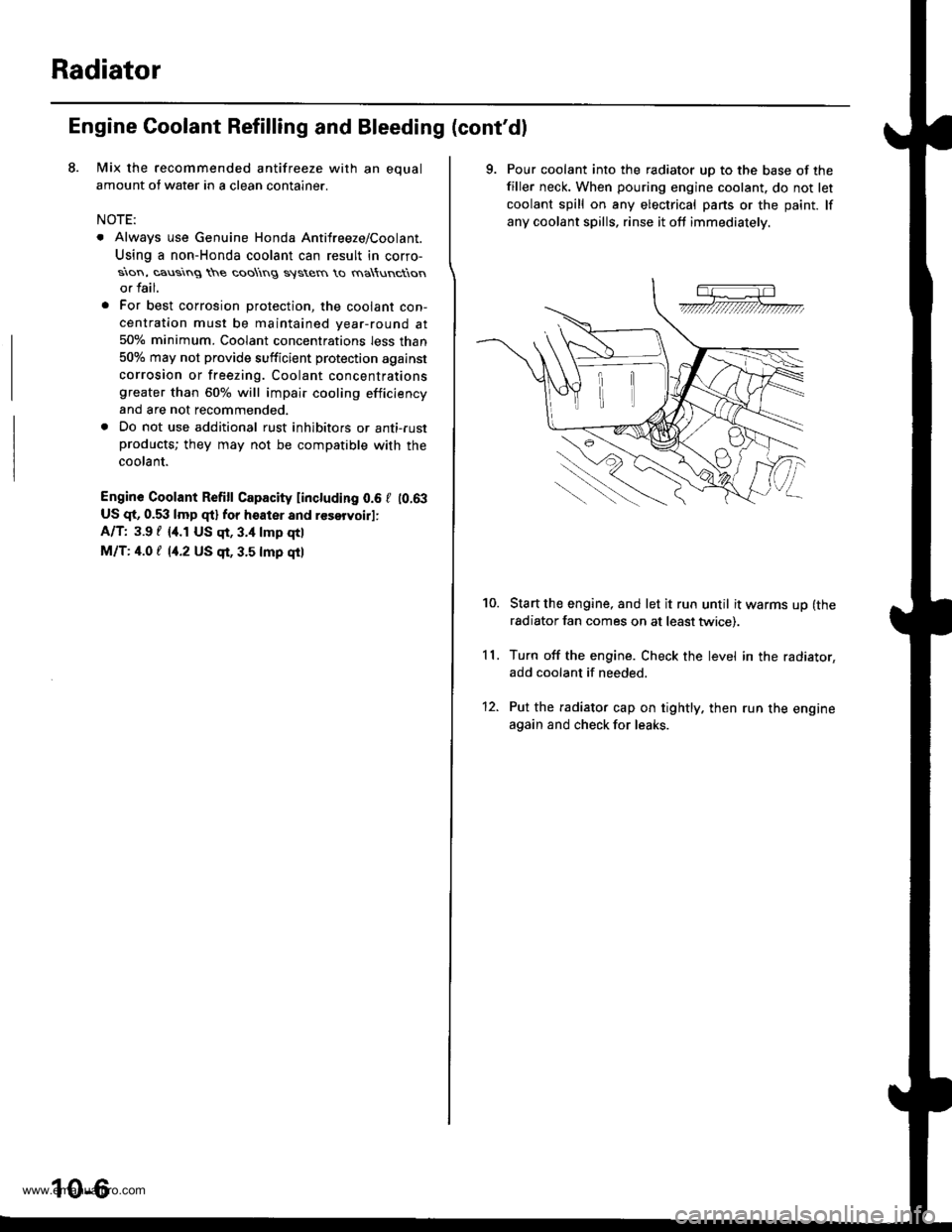
9. Pour coolant into the radiator uD to the base of the
filler neck. When pouring engine coolant. do not let
coolant spill on any electrical pans or the paint. lf
any coolant spills, rinse it oft immediately.
Start the engine, and let it run until it warms up (the
radiator fan comes on at least twice).
Turn off the engine. Check the level in the radiator,
add coolant if needed.
Put the radiator cap on tightly. then run the engine
again and check for leaks.
11.
10.
12.
www.emanualpro.com
Page 442 of 1395
MaintenanceBack-up Light Switch
Transmission Fluid
NOTE: Check the fluid with the engine OFF and vehicle
on level ground.
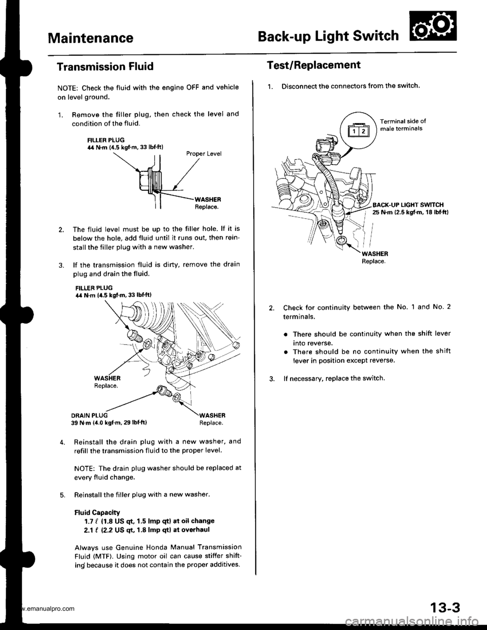
1. Remove the filler plug. then check the level and
condition of the fluid.
FILLER PLUG44 N.m {4.5 kgf.m. 33 lbf ftl
ll
Ptopet Level
\--ril /
HllllllTl /
Hllllrlll /_rf-F{--rno."."
ll| | Replaco.
The fluid level must be up to the filler hole. lf it is
below the hole, add fluid until it runs out. then rein-
stall the tiller plug with a new washer.
lf the transmission fluid is diny, remove the drain
plug and drain the fluid.
FILLEB PLUGa,a N.m 14.5 kgf..n. 33 lbt'ftl
DRAIN PLUG39 N m (4.0 kgf.m, 29 lbf'ft)WASHERReplace.
Reinstall the drain plug with a new washer. and
refill the transmission fluid to the proper level.
NOTE: The drain plug washer should be replaced at
every fluid change.
Reinstall the filler plug with a new washer.
Fluid Capacity
1.7 / {1.8 US qt, 1.5 lmp qtl at oil change
2.1 ! 12.2 US qt, 1.A lmp qtl at overhaul
Alwavs use Genuine Honda Manual Transmission
Fluid (MTF). Using motor oil can cause stiffer shift-
ind because it does not contain the proper additives.
Test/Replacement
1. Disconnect the connectors from the switch.
Terminal side oImale lerminals
BACK.UP LIGHT SWTTCHr 25 N.m 12.5 kgt m, 18 lbf.ftl
WASHERReplace.
Check for continuity between the No. 1 and No. 2
terminals.
. There should be continuity when the shift lever
tnto reverse.
. There should be no continuity when the shift
lever in position except reverse,
lf necessary, replace the switch.
13-3
www.emanualpro.com
Page 677 of 1395
Pressure Testing
Changing
NOTE: Keep all foreign particles out of the transmis-
sion.
1. Bring the transmission up to operating temperature
(the radiator fan comes on) by driving the vehicle.
Park the vehicle on level ground. turn the engane
off. then remove the drain Plug.
NOTE: lf a cooler flusher is to be used, see page
14-264 and 14-265.
TRANSMISSIONEND COVER
DRAIN18 x 1.5 mmSEALING WASHEBReplace.49 N.m {5.0 kgt.m, 36 lbf.tl)
Reinstall the drain plug with a new sealing washer,
then refill the transmission with the recommended
fluid to the uDper mark on the dipstick. Always use
Genuine Honda Premium Formula Automatic
Transmission Fluid (ATF) Using a non-Honda ATF
can affect shift quality.
Automatic Transmission Fluid Capacity:
4WD;
2.9 { (3.1 US qt. 2.6 lmp qt) 8t change
5.8 ? {7.2 US $, 6.0 lmp qt} at ovethaul
2WD:
2.7 | l2.S US qt,2.1lmp qtl ai change
5.9 ? {6.2 US $, 5.2 lmp qtl at ovolhaul
2.
a
a
1.
Wlrile testing, be careful of the rotaling wheols.
Mako sure lifts, iacks, and safety stands ar€ placed
properly (see scction 11.
Before testing, be sure the transmission fluid is
filled to the proPer level.
4WD:
Raise the vehicle (see section 11.
2WD:
Raise the front of the vehicle, and make sure it is
securely supported. Set the parking brake, and block
both rear wheels securely.
Allow all four wheels {4WD) or front wheels (2wD}
to rotate freely.
Warm up the engine (the radiator fan comes on),
then stop it and connect the tachometer.
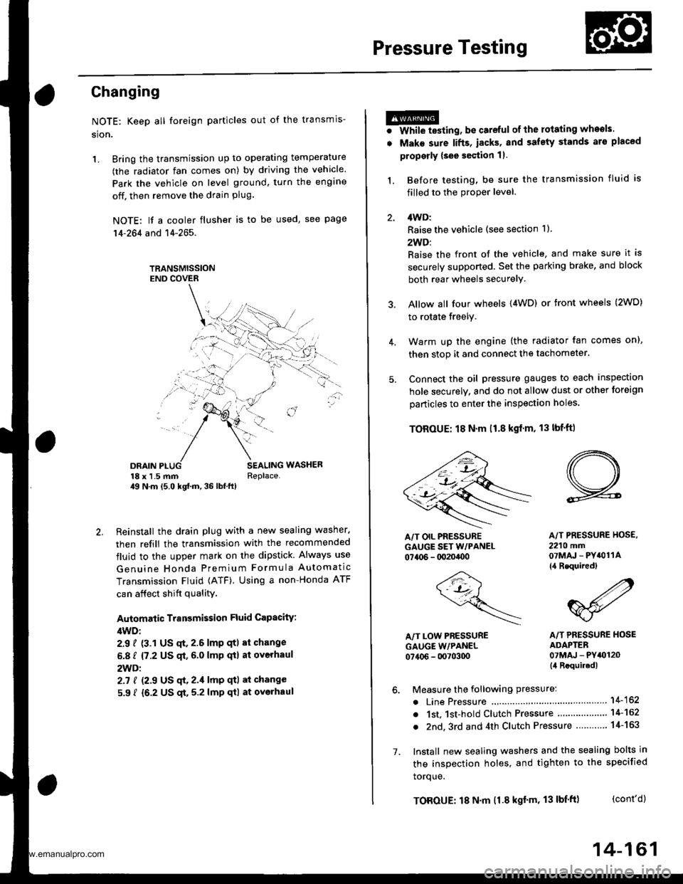
Connect the oil pressure gauges to each inspection
hole securely, and do not allow dust or other foreign
particles to enter the inspection holes.
TOROUE: 18 N'm ll.8 kgf'm, 13 lbf'ft)
5.
A/T PRESSURE HOS€,2210 mm07MAJ - PYiOllA
{4 Requircd}
,4'/"' ,a
W'
A/T PRESSURE HOSEADAPTER07MAJ - PYt0120(il Rcquiledl
6. Measure the following Pressure:. Line Pressure ..........,14-162
. 1st. 1st-hold Clutch Pressure .............'. 14-162
. 2nd,3rd and 4th Clutch Pressure .......... 14-163
7. Install new sealing washers and the sealing bolts in
the inspection holes, and tighten to the specified
toroue.
(cont'd)
A/T OIL PRESSUREGAUGE SET W/PANEL07{06 - 0020400
/4\\-J-- (
+..\.-.\-'-\
A/T LOW PBESSUREGAUGE w/PANEL07406 - 0070300
TOROUE: 18 N'm 11.8 kgf'm, 13 lbf'ft)
14-161
www.emanualpro.com
Page 794 of 1395
Description
Rear Differential
Outline
The Real-time 4WD-Dual Pump System model has a hydraulic clutch and a differential mechanism in the rear differential
assembly. Under normal conditions, the vehicle is driven by the front wheels. However, depending on to the driving force
of the front wheels and the road conditions. the system instantly transmits appropriate driving force to the rear wheels
without requiring the driver to switch between 2WD (tront wheel drive) and 4WD (four wheel drive). The switching mecha-
nism between 2WD and 4WD is integrated into the rear differential assembly to make the system light and compact.
ln addition, the dual-pump system switches off the rear-wheel-drive force when braking in a forward gear. This allows the
braking system to work properly on models equipped with an Anti-lock Braking System (ABS).
Construction
The rear differential assembly consists of the torque control differential case assembly and the rear differential carrier
assembly. The torque control differential case assembly consists of the differential clutch assembly, the companion
flange, and the oil pump body assembly. The rear differential carrier assembly consists of the differential mechanism. The
differential drive and driven gears are hypoid gears.
The oil pump body assembly consists of the front oil pump, the rear oil pump, the hydraulic control mechanism, and the
clutch piston. The clutch piston has a disc spring that constantly provides the differential clutch assembly with a preset
torque to Drevent abnormal sound.
The clutch guide in the differential clutch assembly is connected to the propeller shaft via the companion flange, and it
receives the driving force lrom the transfer assembly. The clutch guide rotates the clutch plate and the front oil pump in
the oil pump body.
The clutch hub in the differential clutch assembly has a clutch disc that is splined with the hypoid drive pinion gear. The
hypoid drive gear drives the rear oil pump.
The front and rear oil pumps are trochoidal pumps. The rear oil pump capacity is 2.5 percent larger that the front oil pump
to handle the rotation difference between the front and rear wheels caused by worn front tires and tight corner braking.
The oil pumps are designed so the fluid intake works as a fluid discharge when the oil pumps rotate in reverse. Genuine
Honda CVT fluid is used instead of differential fluid.
Operation
When there is a difference in rotation speed between the front wheels (clutch guide) and rear wheels (hypoid driven gear),
hydraulic pressure from the front and rear oil pumps engages the differential clutch, and drive force from the transler
assembly is applied to the rear wheels.
The hydraulic pressure control mechanism in the oil pump body selects 4WD mode when the vehicle is started abruptly,
or when accelerating in a forward or reverse gear (causing rotation difference between the front and rear wheels). or
when braking in reverse gear {when decelerating). lt switches to 2WD mode when the vehicle is driven at a constant speed
in forwar! or reverse gear (when there is no rotation difference between the front and rear wheels), or when braking in a
fo rwa rd gear (when decelerating).
To protect the system, the differential clutch assembly is lubricated by hydraulic pressure generated by the oil pumps in
both 4WD and 2WD modes. Also, the thermal switch relieves the hydraulic pressure on the clutch piston and cancels 4WD
mode if the temDerature of the differential fluid rises above normal.
www.emanualpro.com
Page 804 of 1395
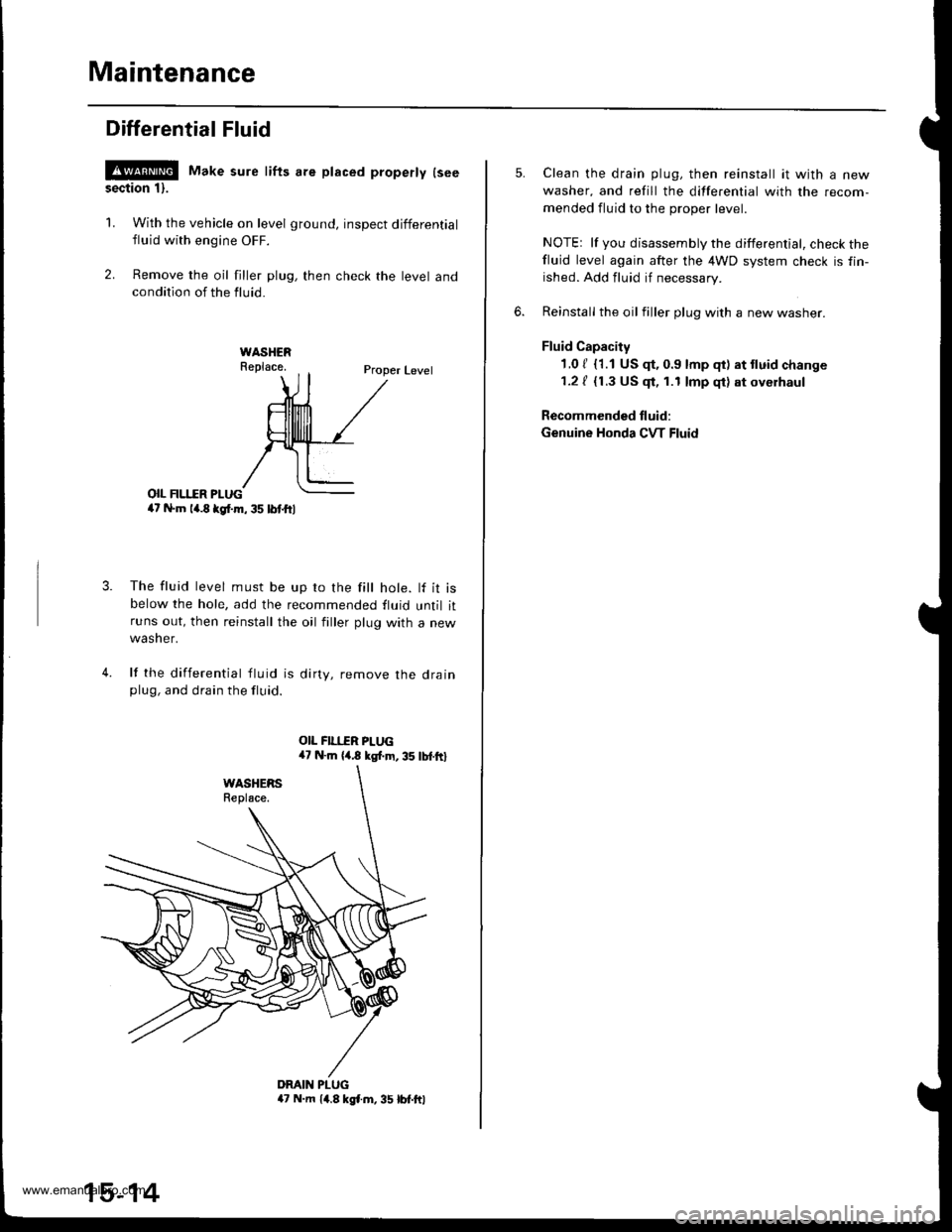
Maintenance
Differential Fluid
!@ Make sure lifts are placed properly lseesection 1).
1. With the vehicle on level ground, inspect differential
fluid with engine OFF.
2. Remove the oil filler plug, then check the level andcondition of the fluid.
Proper Level
o|I FII.IIR PI-UG4t N.m la.8 kgl.m, 35 lbl.ftl
The fluid level must be up ro the fill hole. lf it isbelow the hole, add the recommended fluid until itruns out, then reinstall the oil filler plug with a new
wasner.
lf the differential tluid is dirty, remove the drainplug, and drain the fluid.
4.
DMIN PLUGa7 N.m 14.8 kgl.m, 35 lbt.ftl
15-14
Clean the drain plug, then reinstall it with a new
washer, and refill the differential with the recom-
mended fluid to the proper level.
NOTEr lf you disassembly the differential, check thefluid level again after the 4WD system check is fin-
ished. Add fluid if necessary.
Reinstall the oil filler plug with a new washer.
Fluid Capacity
1.0 / {1.1 US $, 0.9 lmp qt) at tluid change
1.2 / {1.3 US $, 1.1 lmp qt) at oyerhaul
Recommended fluid:
Genuine Honda CVT Fluid
www.emanualpro.com