oil pressure terminal HONDA CR-V 1999 RD1-RD3 / 1.G Workshop Manual
[x] Cancel search | Manufacturer: HONDA, Model Year: 1999, Model line: CR-V, Model: HONDA CR-V 1999 RD1-RD3 / 1.GPages: 1395, PDF Size: 35.62 MB
Page 177 of 1395

Oil Pressure SwitchOil Pressure
Testing
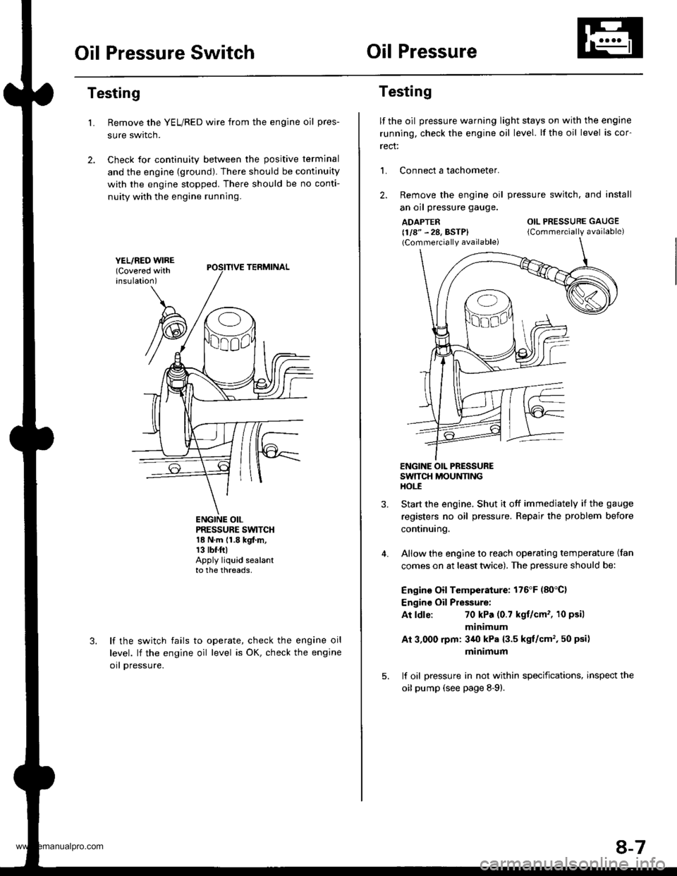
Remove the YEL/RED wire from the engine oil pres-
sure swrtcn.
Check for continuity between the positive terminal
and the engine {ground). There should be continuity
with the engine stopped. There should be no conti-
nuity with the engine running.
L
PRESSURE SWTCH18 N.m {1.8 kgf.m,13 tbr.ftlApply liquid sealantto the threads,
lf the switch fails
level. lf the engine
orl pressure.
to operate, check the engine oil
oil level is OK, check the engine
Testing
lf the oil pressure warning light stays on with the engine
running, check the engine oil level. lf the oil level is cor-
rect:
L Connect a tachometer.
2. Remove the engine oil
an oil pressure gauge.
ADAPTER(1/8" - 28, BSTP)(Commercially available)
pressure switch. and install
OIL PRESSURE GAUGE
{Commercially available)
4.
ENGINE OIL PRESSURESWTTCH MOUNNNGHOt-E
Start the engine. Shut it off immedjately if the gauge
registers no oil pressure. Repair the problem before
continuing.
Allow the engine to reach operating temperature (fan
comes on at least twice). The pressure should be:
Engino Oil Temperature: 176'F (80'C)
Engine Oil Pressure:
At ldle:70 kPa (0.7 kgt/cm'�, 10 psil
minimum
Ai 3,000 rpm: 3/r0 kPa {3.5 kgt/cm', 50 psi)
minimum
lf oil pressure in not within specifications, inspect the
oil pump (see page 8-9).
8-7
www.emanualpro.com
Page 288 of 1395

PGM-FI System
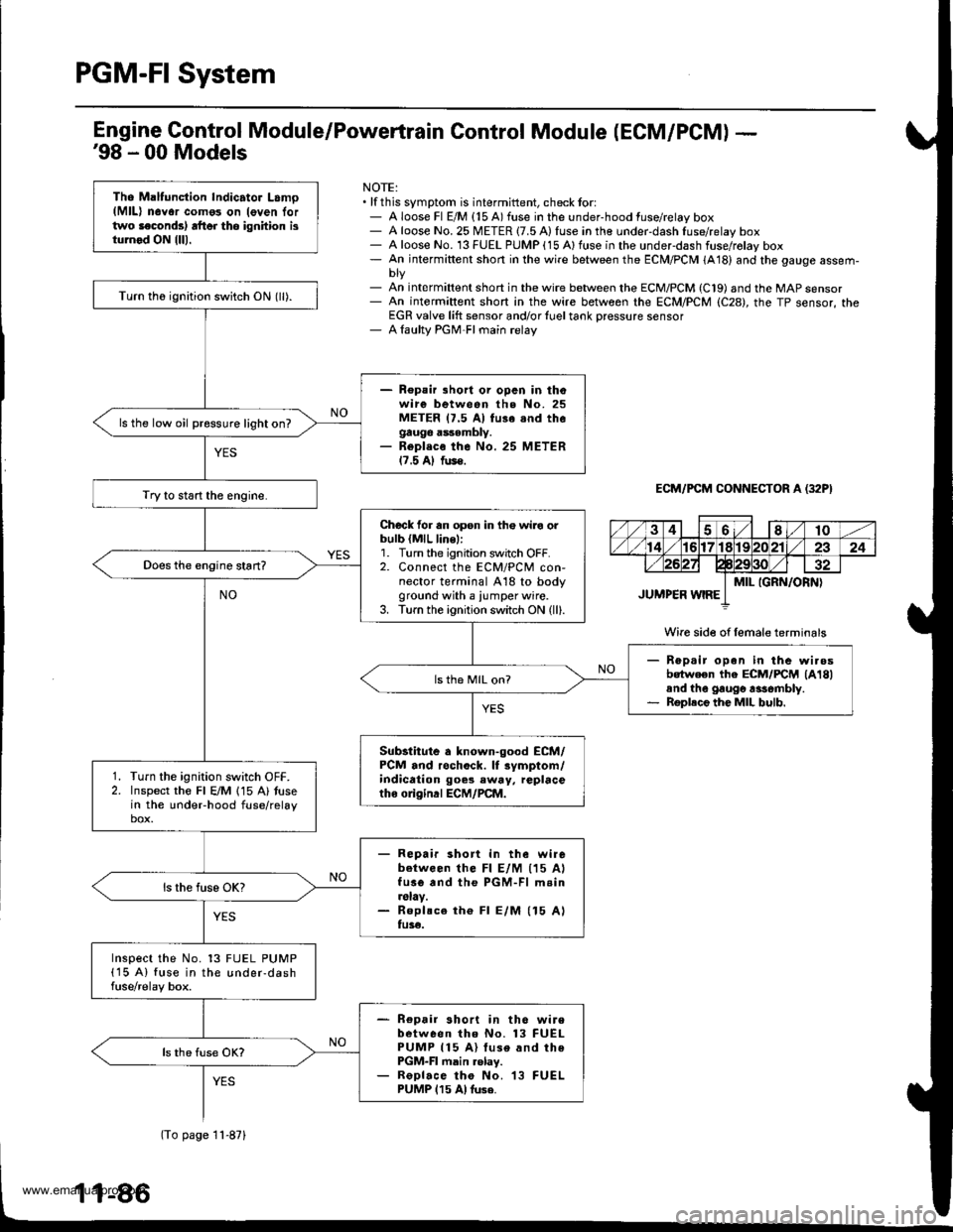
Tho Maltunction Indicator Lamo(MlL) n6Yor como3 on leven lortwo laconds) rft6r tho ignhion isturnod ON {lll.
Turn th6 ignition switch ON (ll).
- Repair lhort or opcn in thowire between the No. 25METER 17.5 Al fu3e snd thegauge assembly.- Repl.co the No. 25 METER17.5 Al fus€.
ls the low oil pressure light on?
Try to start the engine.
Chock for an opsn in th€ wiro orbulb {MlL line,:1. Turn the ignition switch OFF.2. Connect the ECM/PCM con-nector terminal A18 to bodyground with a iumper wire.3. Turn the ignition switch ON (ll).
Rep.ir open in the wi.osbotween the ECM/FCM lA18land the gaugo rasombly.Roplece the MIL bulb.
ls th6 MIL on?
Substitute a known-good ECM/PCM and rochock. lf rymptom/indication goes eway, replacetho o gind ECM/PCM.
Turn the ignition switch OFF.Inspect the Fl E/M 115 A) tusein the undeFhood fuse/relaybox.
- Repair short in the wirebetween lhe Fl E/M (15 AlfusG and the PGM-Fl m.in.slay.- Roplsce th€ Fl E/M (15 Alfu3€.
Inspect the No. 13 FUEL PUMP(15 A) fuse in the under-dashfuse/relay box.
- Repair short in th6 wirebetween tho No. 13 FUELPUMP 115 A) luse and thePGM-FI main .elay.- ReDlace tho No. 13 FUELPUMP 115 Al tuse.
Engine Gontrol Module/Powertrain Control Module (ECM/PCM) -'98 - 00 Models
NOTE:. lf this symptom is intermittent, check tor:- A loose Fl E/M {15 A) fuse in the under-hood fuse/relay box- A loose No. 25 METER {7.5 A) fuse in the under-dash fuse/relay box- A loose No. 13 FUEL PUMP (15 Alfuse in the underdash fuse/rolay box- An intermiftent short in the wire between the ECM/PCM (A18) and the gauge assem-
- An int€rmiftent short in the wire between the ECM/PCM (C19) and the MAP sensor- An intermiftent short in the wire between rhe ECM/PCM (C28), the TP sensor, theEGR valve lift sensor and/or {uel tank Dressure sensor- A laulty PGM-FI main relay
ECM/PCM CONNECTOR A (32P}
Wire side of female terminals
(To page 11-871
www.emanualpro.com
Page 1174 of 1395
![HONDA CR-V 1999 RD1-RD3 / 1.G Workshop Manual
Connector ldentification and Wire Harness Routing
Engino Wire Harness
Connecto; or
Terminal
Number of
CavitiesLocationConneqts toNotos
c101
c102
c103
c 104
c105
c105
c106
c 107
c 108
c 109
c]10
c1ll HONDA CR-V 1999 RD1-RD3 / 1.G Workshop Manual
Connector ldentification and Wire Harness Routing
Engino Wire Harness
Connecto; or
Terminal
Number of
CavitiesLocationConneqts toNotos
c101
c102
c103
c 104
c105
c105
c106
c 107
c 108
c 109
c]10
c1ll](/img/13/5778/w960_5778-1173.png)
Connector ldentification and Wire Harness Routing
Engino Wire Harness
Connecto; or
Terminal
Number of
CavitiesLocationConneqts toNotos
c101
c102
c103
c 104
c105
c105
c106
c 107
c 108
c 109
c]10
c1l'l
c112
c113
c't 14
cl16
cl16
c117
c118
c119
c120
c121
c't22
c't23
c't25
cl26
cl27
cr 28
cl29
c130
c131
c132
c 133
c134
c134
c135
c 136
10
6
1
2
1
2
1
10
20
31
16
22
l0
l0'14
14
1
Left side of engine compartment
Left side of engine compartment
Middle of engine
Middle of engine
Left side of engine compartment
Left side of engine compartment
Middle of engine
Middle of engine
Middle of engine
Middle of engine
Middle of engine
Middle of engine
Middle of engine
Middle of engine
Middle of engine
Middle of engine
Middle of engine
Middle of engine
Middle of engine
Middle of engine
Middle of engine
Right side of engine
Middle of engine
Behind right kick panel
Under right side of dash
Under right side of dash
Under right side of dash
Under right side of dash
Under right side of dash
Right side of engine
Right side of engine
Middle of engine
Middle of engine
Middle of engine
Middle of engine
Middle of engine
Middle of engine
Left side of engine compartment
Middle of engine
Middle of engine
Main wire harness (C304)
Main wire harness (C305):'97 - 98 models
No. 1 fuel injector
Crankshaft speed fluctuation (CKF) sensor
Alternator
Alternator
Engine oil pressure switch
No.2 fuel injector
Evaporative emission (EVAP) purge
control solenoid valve
No. 3 fuel injector
No. 4 fuel injector
Primary heated oxygen sensor(Primary HO2S) (sensor 1)
Radiator fan switch
Coolant temperature sending unit
Engine coolant temperature (ECT) sensor
Mainshaft speed sensor
Lock-up control solenoid valve
Back-up light switch
Shift control solenoid valve
Linear solenoid valve
Countershaft speed sesnsor
Starter solenoid
Distributor
Junction connector
PCM
ECIWPCM
ECM/PCM
ECM/PCM
Main wire harness (C,|:}1)
IVT gear position switch
Vehicle speed sensor (VSS)
Throttle position (TP) sensor
MAP sensor
ldle air control (lAC)valve
lntake air temperature (lAT) sensor
Junction connector
Junction connector
Power steering pressure (PSP) switch
Junction connector
Knock sensor (KS)
A/r
USA
Canada
Alr
AlT
M/'r
Afi
'97mooel
'97 model'98 - 00
mooets
'99 - 00
models
T101
r102
Left side of en0ine companment
Right side of engine compartment
Alternator
Under-hood fuse/relay box
G101Middle of engineEngine ground, via engine wire harness
23-14
www.emanualpro.com
Page 1215 of 1395

Gauge Assembly
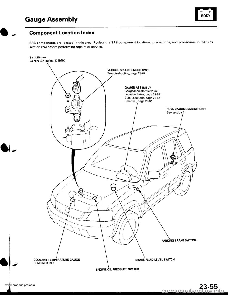
Component Location Index
SRS components are located in this area. Review the SRS component locations, precautions, and procedures in the SRS
section {24} before performing repairs or service.
I x 1.25 mm24 N.m {2.4
VEHICLE SPEED SENSOF {VSS'Troubleshooting, page 23-62
GAUGE ASSEMBLYGau ge/lndicator/TerminalLocation Index, page 23-56Bulb Locations, page 23-57Removal, page 23-61
J-
FUEL GAUGE SENDING UNITSee section 1 l
PARKING BRAKE SWITCH
COOLANT TEMPERATURE GAUGESENDING UNITBRAKE FLUID LEVEL SWITCH
ENGINE OIL PRESSURE SWITCH
www.emanualpro.com