self diagnostic HONDA CR-V 1999 RD1-RD3 / 1.G Workshop Manual
[x] Cancel search | Manufacturer: HONDA, Model Year: 1999, Model line: CR-V, Model: HONDA CR-V 1999 RD1-RD3 / 1.GPages: 1395, PDF Size: 35.62 MB
Page 283 of 1395

Fuel Cut-off Control
. During deceleration with the throttle valve closed, current to the fuel injectors iscutoffto improvefuel economyat
speeds over 970 rpm ('97 - 98 models), 920 rpm ('99 - 00 modelsl.
. Fuel cut-off action also takes place when engine speed exceeds 6,500 rpm ('97 - 98 models), 6900 rpm ('99 - 00
models), regardless of the position of the throttle valve, to protect the engine from over-rewing.
With Ay'T model. the PCM cuts the fuel at engine speeds over 5,000 rpm when the vehicle is not moving.*'�
4,./C Comoressor Clutch Relav
When the ECM/PCM receives a demand for cooling from the air conditioning system, it delays the compressor from
being energized, and enriches the mixture to assure a smooth transition to the Ay'C mode.
Evaporative Emission (EVAP) Purge Control Solenoid Valve
When the engine coolant temperature is above 154"F (68'C), the ECM/PCM controls the EVAP purge control solenoid
valve which controls vacuum to the EVAP purge control canister,
Alternator Control
The system controls the voltage generated at the alternator in accordance with the electrical load and driving mode.
which reduces the engine load to improve the fuel economy.
PCM Fail-saf e/Back-up Functions
1. Fail-safe Function
When an abnormality occurs in a signal from a sensor, the ECM/PCM ignores that signal and assumes a pre-pre
grammed value for that sensor that allows the engine to continue to run.
2. Back-up Function
When an abnormality occurs in the ECM/PCM itself, the fuel injectors are controlled by a back-up circuit independent
of the system in order to permit minimal driving.
3. Self-diagnosis Function IMalfunction Indicator Lamp (MlL)l
When an abnormality occurs in a signal from a sensor, the ECM/PCM supplies ground for the MIL and stores the DTC
in erasable memory. When the ignition is initially turned on {ll), the ECM/PCM supplies ground for the MIL for two
seconds to check the MIL bulb condition.
4. Two Trio Detection Method
To prevent false indications, the Two Trip Detection Method is used for the HO2S*1, fuel metering-related. idle control
system, ECT sensor and EVAP control system self-diagnostic functions. When an abnormality occurs, the ECM/PCM
stores it in its memory. When the same abnormality recurs after the ignition switch is turned OFF and ON (ll) again,
the ECM/PCM informs the driver by lighting the MlL. However, to ease troubleshooting, this function is cancelled
when you jump the service check connector, The MIL will then blink immediately when an abnormality occurs.
5. Two (or Three) Driving Cycle Detection Method {'97 model)
A "Driving Cycle" consists of starting the engine, beginning closed loop operation, and stopping the engine. lf misfir-
ing that increases emissions or EVAP control system malfunction is detected during two consecutive driving cycles.
or TWC deterioration is detected during three consecutive driving cycles, the ECM/PCM turns the MIL on. However, to
ease troubleshooting, this function is cancelled when you jump the service check connector. The MIL will then blink
immediately when an abnormality occurs.
*1: '97 - 98 models*2: '99 - 00 models
5.
www.emanualpro.com
Page 577 of 1395
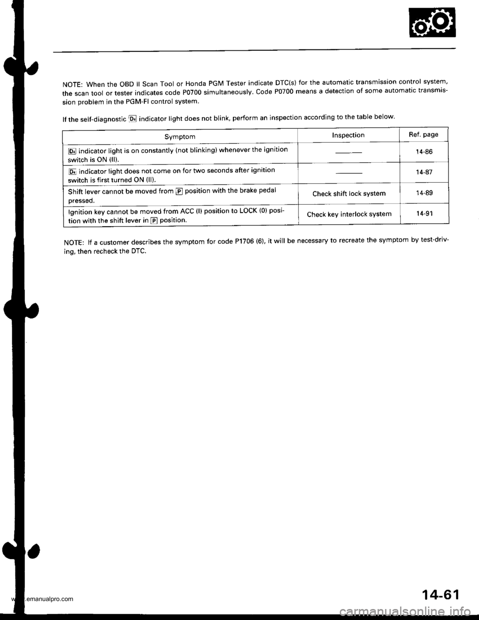
NOTE: When the OBD ll Scan Tool or Honda PGM Tester indicate DTC(s) for the automatic transmission control system'
the scan tool or tester indicates code P0700 simultaneously. code P07oo means a detection of some automatic transmis-
sion problem in the PGM-Fl control system
lf the self-diagnostic E indicator light does not blink, perform an inspection according to the table below.
NOTE: lf a customer describes the symptom for code P1706 (6), it will be necessary to recreate the symptom by test-driv-
ing, then recheck the OTC.
SymptomInspectionRef. page
E indicator light is on constantly (not blinking) whenever the ignition
switch is ON (ll).14-86
E indicator light does not come on for two seconds after ignition
switch is first turned ON (ll).
't 4-41
Shift lever cannot be moved from @ position with the brake pedal
Dressed,Check shift lock system14-89
lgnition key cannot be moved from ACC (l) position to LOCK {0) posi
tion with the shift lever in E position.Check keY interlock system14-91
14-61
www.emanualpro.com
Page 579 of 1395
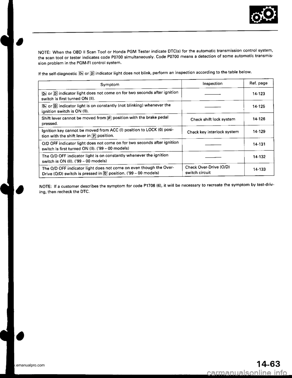
NOTE: When the OBD ll Scan Tool or Honda PGM Tester indicate DTC(S) for the automatic transmission control system,
the scan tool or tester indicates code P0700 simultaneously. Code P0700 means a detection of some automatic transmis-
sion problem in the PGM-Fl control system.
lf the self-diagnostic E or E indicator light does not blink, perform an inspection according to the table below.
NOTE: lf a customer describes the symptom for code P17OO (6), it will be necessary to recreate the symptom by test-driv-
ing. then recheck the DTC.
SymptomInspectionRef. page
E or E indicator light does not come on for two seconds after ignition
switch is first turned ON (ll).14-123
E or E] indicator light is on constantly (not blinking) whenever the
ignition switch is oN {ll).
14-125
Shift lever cannot be moved from E position with the brake pedal
presseo.Check shift lock system14-'t26
lgnition key cannot be moved from ACC (l) position to LOCK (0) posi-
tion with the shift lever in E position.Check key interlock system14-129
O/D OFF indicator light does not come on for two seconds after ignition
switch is first turned ON (ll). ('99 - 00 models)14-131
The O/D OFF indicator light is on constantly whenever the ignition
switch is ON (ll). ('99 - 00 models)14-132
The O/D OFF indicator light does not come on even though the Over-
Drive (O/Dl switch is pressed in E position. ('99 - 00 models)
Check Over-Drive {O/D}
switch circuit14-133
14-63
www.emanualpro.com
Page 959 of 1395
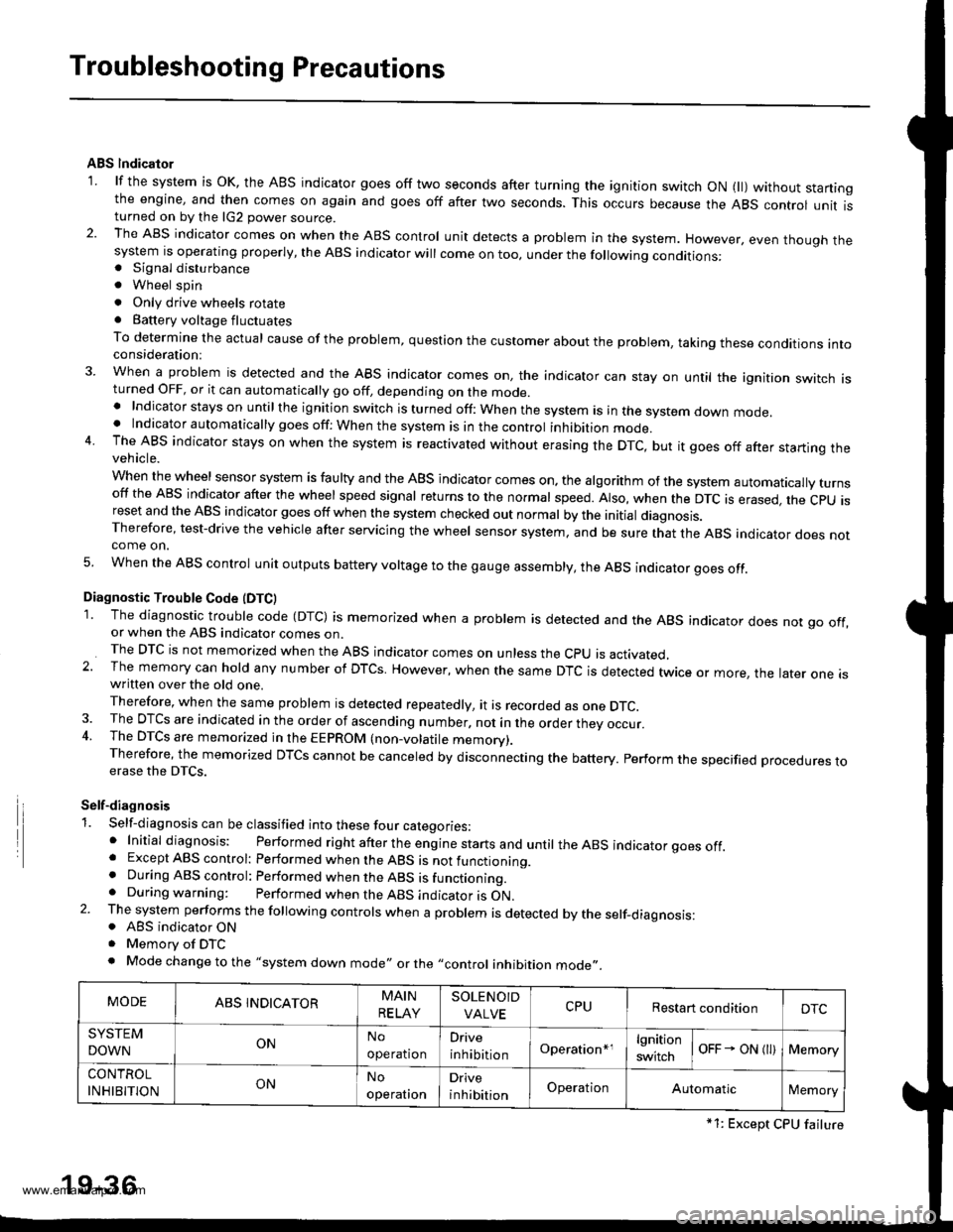
Troubleshooting Precautions
ABS lndicalor
1 lf the system is oK, the ABS indicator goes off two seconds after turning the ignition switch oN 1l) wathout staningthe engine, and then comes on again and goes off after two seconds. This occurs because the ABS control unit isturned on by the lG2 power source.2. The ABS indicator comes on when the ABS control unit detects a problem in the system. However, even thouoh thesystem is operating properly, the ABs indicator will come on too, under the following conditions:. Signal disturbance
. Wheel spin
. Only drive wheels rotate. Battery voltage fluctuates
To determine the actual cause of the problem, question the customer about the problem, taking these conditions intoconsideration:
3 When a problem is detected and the ABS indicator comes on, the indicator can stay on until the ignition switch isturned OFF, or it can automatically go off, depending on the mode.. Indicator stays on untilthe ignition switch is turned off: When the system is in the system down mode.. Indicator automatically goes off: When the system is in the control inhibition mode.4 The ABS indicator stays on when the system is reactivated without erasing the DTC, but it goes off after starting thevehicle.
When the wheel sensor system is faulty and the ABS indicator comes on. the algorithm of the system automatically turnsoff the ABS indicator after the wheel speed signal returns to the normal speed. Also, when the DTc is erased, the cpu isreset and the ABS indicator goes off when the system checked out normal by the initial diagnosis.Therefore, test-drive the vehicle after servicing the wheel sensor system. and be sure that the ABS indicator does notcome on.
5 When the ABS control unit outputs battery voltage to the gauge assembly, the ABS indicator ooes off.
Diagnostic Trouble Code (DTCI
1. The diagnostic trouble code (DTc) is memorized when a problem is detected and the ABS indicator does not go off,or when the ABS indicator comes on.The DTc is not memorized when the ABS indicator comes on unress the cpu is activated,2 The memory can hold any number of DTCs. However, when the same DTc is detected twice or more, the tater one iswritten over the old one.
Therefore, when the same problem is detected repeatedly, it is recorded as one DTC.3. The DTCs are indicated in the order of ascending number, not in the order they occur.4. The DTCS are memorized in the EEPROM (non-volatile memorv).Therefore, the memorized DTcs cannot be canceled by disconnecting the battery. perform the specified procedures toerase the DTCS.
Self-diagnosis
1. Self-diagnosis can be classified into these four categories:' Initial diagnosis: Performed right after the eng ine starts and untir theABS indicator goes off.. Except ABS control: Performed when the ABS is not functioning.. During ABS control: Performed when the ABS is functioning.. During warning: Performed when the ABS indicator is ON.2. The system performs the fo|owing contrors when a probrem is detected by the serf-diagnosis:. ABS indicator ON. Memorv of DTC. Mode changetothe "system down mode,, or the ,,control inhibition mode,,.
MODEABS INDICATORMAIN
RELAY
SOLENOID
VALVECPURestart conditionDTC
SYSTEM
DOWNONNo
operation
Drive
inhibitionOperation*rlgnition
switchoFF - ON l)Memory
CONTROL
INHIBITIONONNo
operal|on
Drive
inhibitionOperationAutomaticlMemory
*1: Except CPU failure
19-36
www.emanualpro.com
Page 1100 of 1395
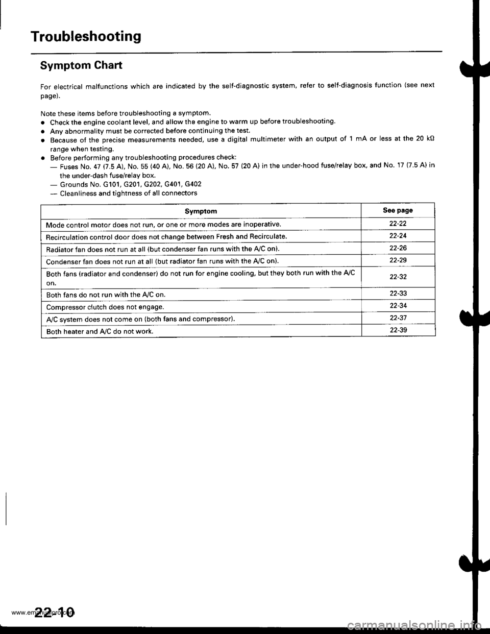
Troubleshooting
Symptom Ghart
For electrical malfunctions which are indicated by the self-diagnostic system, reter to selt-diagnosjs function (see next
page).
Note these items before troubleshooting a symptom.
. Check the engine coolant level, and allow the engine to warm up before troubleshooting.
. Anv abnormality must be corrected before continuing the test.
. Because of the precise measurements needed, use a digital multimeter with an output of 1 mA or less at the 20 kO
range when testing.
. Before performing any troubleshooting procedures check:
- Fuses No. 47 17.5 AJ, No. 55 (40 A), No. 56 (20 A), No. 57 (20 A) in the under-hood fuse/relay box, and No. 17 {7.5 A) in
the under-dash fuse/relay box.._ Grounds No. G101, G201, G202, G401, G4O2
- Cleanliness and tightness of all connectors
SymptomSse pags
Mode control motor does not run, or one or more modes are inoperative.
Recirculation control door does not change between Fresh and Recirculate.22-24
Radiator fan does not run at all (but condenser fan runs with the AVC on).
Condenser fan does not run at all {but radiator fan runs with the Ay'C on).22-29
Both fans (radiator and condenser) do not run for engine cooling. but they both run with the A,/C
on.
Both fans do not run with the Ay'C on22-33
Compressor clutch does not engage.22-34
AJC svstem does not come on (both fans and compressor).22-37
Both heater and A/C do not work,22-39
22-10
www.emanualpro.com
Page 1101 of 1395
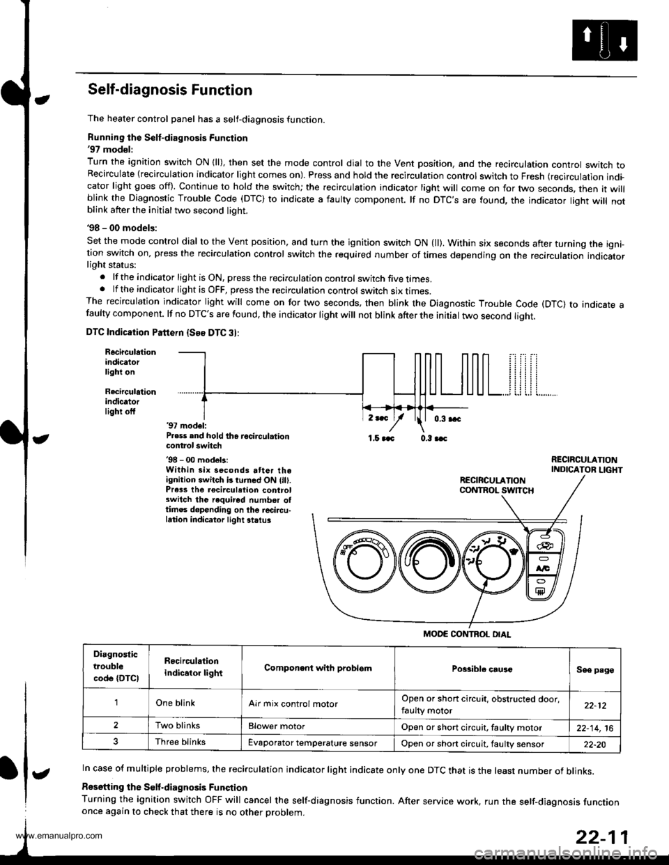
Self-diagnosis Function
The heater control panel has a self-diagnosis function.
Running the Self-diagnosis Function'97 mod€l:
Turn the ignition switch ON {ll), then set the mode control dial to the Vent position, and the recirculation controt switch toRecirculate {recirculation indicator light comes on). Press and hold the recirculation control switch to Fresh (recirculation indi-cator light goes off). Continue to hold the switch; the recirculation indicator light will come on for two seconds. then it willblink the Diagnostic Trouble Code (DTC) to indicate a iaulty component. lf no DTC'S are found, the indicator liqht will notblink atter the initial two second light.
'98 - 00 models:
Set the mode control dial to the Vent position, and turn the ignition switch ON (ll). Within six seconds after turning the igni-tion switch on, press the recirculation control switch the required number of times depending on the recirculation indicatorlight status:
.lftheindicatorlightisON,presstherecirculationcontrol switch five times..lftheindicatorlightisOFF,presstherecirculationcontrol switch six I|mes.The recirculation indicator light will come on for two seconds, then blink the Diagnostic Trouble Code (DTC) to indicate afaulty component. lf no DTC'S are found, the indicator light will not blink after the initial two second liqht.
DTC Indicaiion Pattern {See DTC 3}:
Rocirculationindicatorlight on
Recirculrtionindicatorlighi off'97 model:P.ess and hold th6 recircul.tioncontrol switch'98 - 00 modek:Within six second3 atter theignition switch b turned ON (lll.Prass the rocirculation controlswitch the required number oltimes depending on the r6circu-lation indicator light striu3
,r*
/1.5 aaa 0.3 aac
RECIRCULANONINDICATOR LIGHT
In case of multiple problems, the recirculation indicator light indicate only one DTC that is the least number of blinks.
Resetiing the Solf.diagnosis Funqtion
Turning the ignition switch OFF will cancel the self-diagnosis function. After service work, run the self-diaqnosis functiononce again to check that there is no other Droblem.
MODE CONTROL OIAL
Diagnostic
trouble
code {DTCI
R6circulation
indicator lightComponent with problsmPossiblo causcSee page
'lOne blinkAir mix control molorOpen or short circuit, obstructed door,
faulty motor22-12
2Two blinksElower motorOpen or short circuit, faultv motor22-14,16
Three blinksEvaporator temperature sensorOpon or short circuit, faulty sensor22-20
t
www.emanualpro.com
Page 1104 of 1395
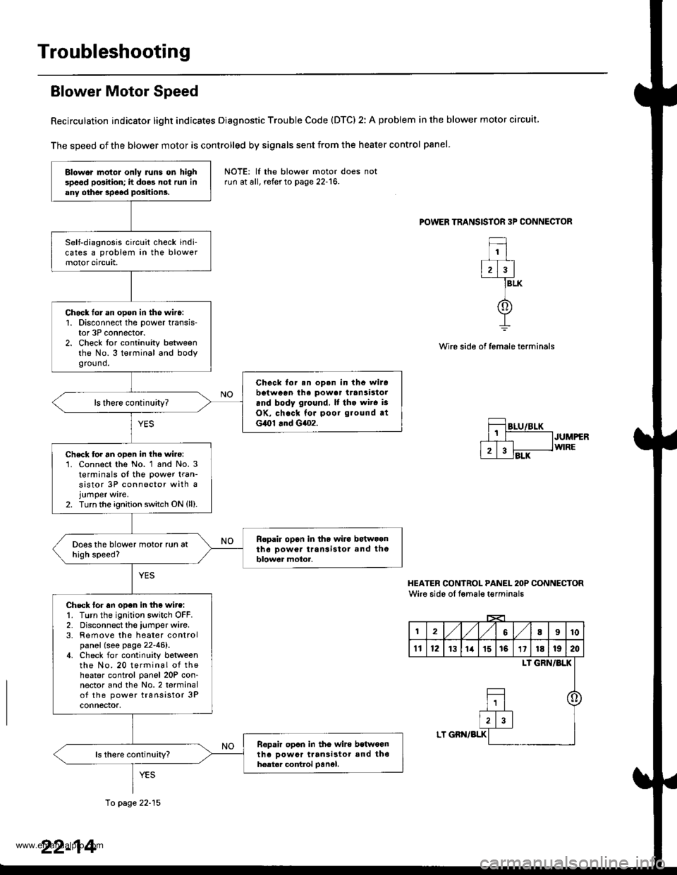
Troubleshooting
Blower Motor Speed
Recirculation indicator light indicates Diagnostic Trouble Code (DTC) 2: A problem in the blower motor circuit
The speed of the blower motor is controlled by signals sent from the heater control panel
POWER TRANSISTOR 3P CONNECTOR
1
2)3
f
BLK
Wire side of female terminals
JUMPERWIRE
HEATER CONIROL PANEL 2OP CONNECTORWire side oI fgmale t€rminals
12,/1,/68I10
't112131ia't51611181920
LI GRN/BLK
o
LT GBN/BLK
Blower motol only runs on highspood position; h does not run inany othe. speod positions.
Self-diagnosis circuit check indi-cates a problem in the blowermotor circuit,
Chack lor.n open in the wire:1. Disconnect the power transis-tor 3P connector.2. Check for continuity betweenthe No.3 terminal and bodygro(1nd.
Chock for.n op.n in thc wirobotween ihe powa. transistorrnd body ground, It tho wir. is
OK, check for poor ground atG,O1 .nd G4o2.
ls there continuity?
Chsck for an opon in the wire:'1. Connect the No. 1 and No. 3t€rminals of the power tran-sistor 3P connector with ajumper ware.2. Turn the ignition switch ON {ll).
Repair op6n in the wiro betwoontho Dower transi3tol and theblowor motor.
Check tor an open in tho wire:1. Turn the ignition switch OFF.2. Disconnect the iumper wire.3. Remove the heater controlpanel (see page 22-46).4. Check for continuity botweenthe No. 20 terminal of theheater control panel 20P con-nector and the No.2 terminalof the power transistor 3Pconnectof,
R€pair opon in tho wire betwoenth6 oowor ttan3i3tor and th6hoatar control oanel.
NOTE: lf the blower motor doesrun at all, refer to page 22-16.
10 page 22-15
22-14
www.emanualpro.com
Page 1110 of 1395
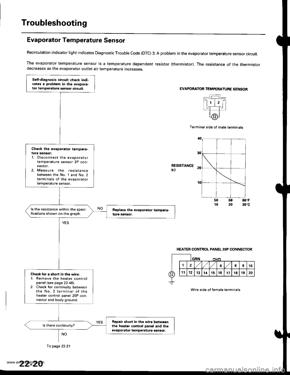
Troubleshooting
Evaporator Temperature Sensor
Recirculation indicator light indicates Diagnostic Trouble code (OTC) 3: A problem in the evaporator temperature sensor circuit.
The evaporator temperature sensor is a temperature dependent resistor {thermistor}. The resistance of the thermistordecreases as the evaporator outlet air temperature increases.
EVAPORATOR TEMPEMTURE SENSOR
Terminal side of mal€ terminals
RESISTANCEko
86'F30"c
HEATER CONTROL PANEL 2OP CONNECTOR
Wire side of fema16 terminals
Self-diagnosis circuit check indicates a problem in the avapora-tor tempeleture ssnsor circuit,
Ch€ck the ev.porato. tempera-ture sensor:1. Disconnect the evaporatortemperature sensor 2P con-
2. Measure the resistancebetween the No. 1 and No. 2torminals of the evaporatortemperature sensor.
ls the resistance within the speci,fications shown on the 9raph.
Check lor a short in the wire:l� Remove the heater controlpanel (see page 22-46).2. Check tor continuity betweenthe No.2 terminal ol theheater control panel 20P con,nector and body ground.
Repai. short in the wir6 betwa€nlhe hoater control Danol and theevaporatoa tampereturc senSoa.
fo page 22.21
www.emanualpro.com
Page 1310 of 1395
)
Supplemental Restraint System (SRS)
Special Tools .."....."" 24-14
Component/Wring Location
lndex - '97 model ..........'.." '.....""" 24-15
Component/Wiring Location
lndex - '98 - 00 models ..............." 24-16
Description .'.........."'.24'17
Circuit Diagram .........24'14
Precautions/Procedures
General Precautions ......".."'........... 24-19
Airbag/Seat Belt Tensioner
Handling and Stolage ....''........... 24-19
SRS Unit Precautions ...............'...... 24-20
lnspeciion After Deployment .......'.24'20
)
with Built-in Short Contact '...'....24-21
Spring-loaded Lock Connectors .."' 24-22
BackProbing SPring-loaded Lock
Conneetors ,.......24-22
Disconnecting the Airbag Connectors and
the Seat Beh Tensioner
Connectors ....'....24-23
Steering-lelated Precautions .......... 24-25
Troubleshooting
Self -diagnostic Procedures ............. 24-26
Reading the DTC .................. .....".."' 24'26
Erasing the DTC Memory ................24-28
Troubleshooting lntermittent
Faifures "'...........24'24
Diagnostic Trouble Gode {DTC}
Chart -'97 model ....""....... "......24-29
Diagnostic Trouble Gode (DTCI
Chart -'98 - 00 models ............. 24-31
SRS Indicator Light Wire
Connections ','," 24'33
Ff owcharts ....-........24'34
Driver's Airbag
Repf acement ..'......21'87
Front Passenger's Airbag
Repfacement .....'.',24'AS
Gable Reel
Replacement .......'.24-91
SRS Unit
Replacement .........24-95
Airbag/Seat Belt Tensioner
Disposaf .................24'97
)-e
www.emanualpro.com
Page 1323 of 1395
Troubleshooting
Self-diagnostic Procedures
The self-diagnostic function of the SRS system allows it to locate the causes of system problems and to store this informa-
tion in memory, For easier troubleshooting, this data can be retrieved via a data link circuit.
. When you turn the ignition switch ON (ll). the SRS indicator will come on. lf it goes off after six seconds, the system is
normal.
. lf there is 8n abnormality, the system locates and defines the problem. stores this information in memory, and turns
the SRS indicator light on. The data will remain in the memory even when the ignition switch is turned off or if the bat-
terv is disconnected.
. When you connect the SCS service connector to the service check connector (2P), and turn the ignition switch ON (ll),
the SRS indicator light will indicate the diagnostic trouble code (DTC) by the number of blinks.
. After reading and recording the DTC, proceed with the troubleshooting forthis code.
Precsutions
. Use only a digital multimeter to check the system. lf it's not a Honda multimeter. make sure its output is 10 mA (0.01 A)
or less when switched to the smallest value in the ohmmeter range. A tester with a higher output could damage the
airbag circuit or cause accidental airbag deployment and possible injury.
. Whenever the ignition switch isON (ll). or has been turned OFF for less than three minutes, be careful nottobumpthe
SRS unit; the airbags could accidentally deploy and cause damage or injuries.
. Before you remove the SRS main harness, disconnect the airbag and tensioner connectors (see page 24-23).
. Make sure the battery is sufficiently charged (see section 23). lf the battery is dead or low, measuring values won't be
correct.
. Do not touch a tester probe to the terminals in the SRS unit or harness connectors, and do not connect the terminals
with a jumper wire. Use only the backprobe set and the SCS service connector.
For backprobing spring-loaded lock type con nectors, .efet to page 24-22.
Reading the DTC
When the SRS indicator light is on, read the DTC using one of these methods;
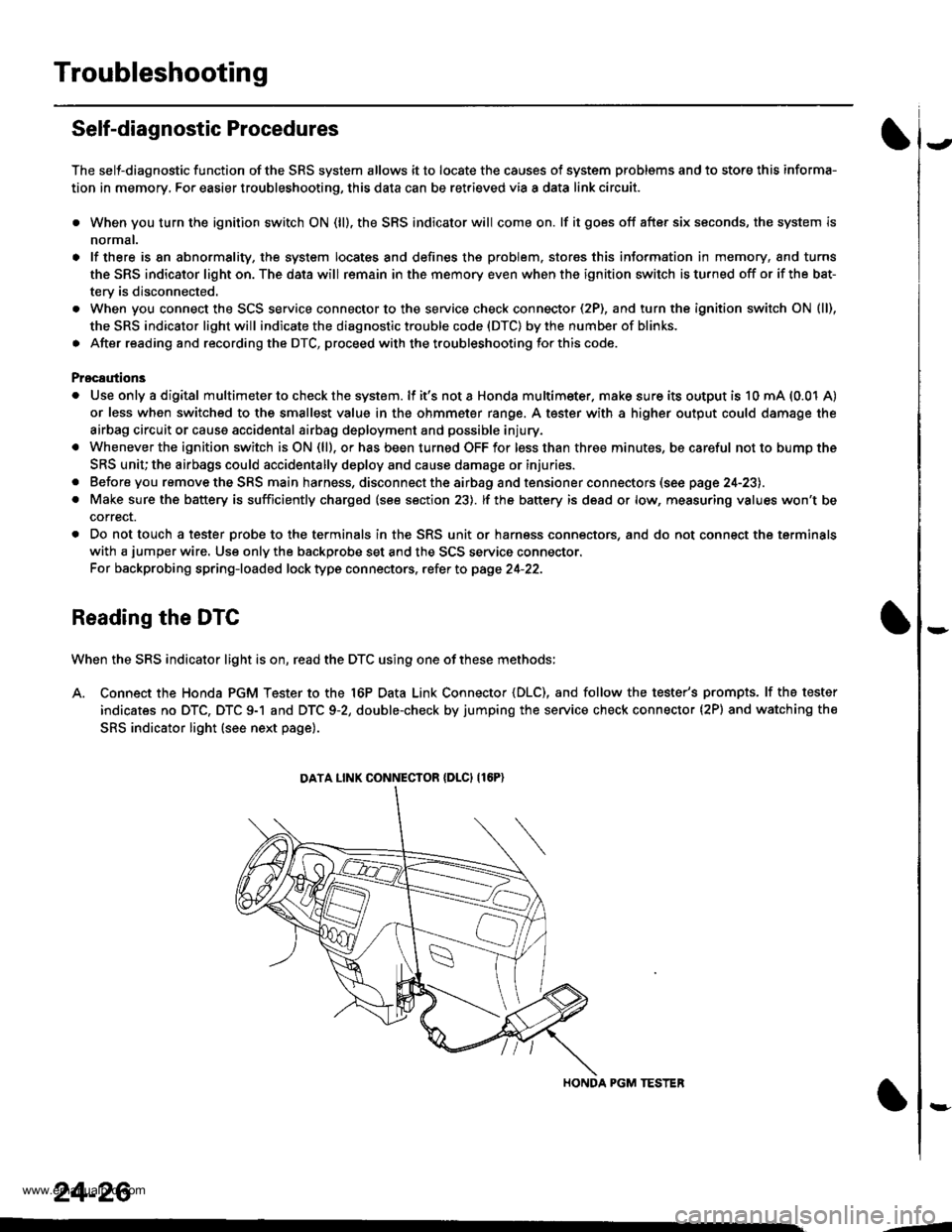
A. Connect the Honda PGM Tester to the 16P Data Link Connector {DLC), and follow the tester's prompts. lf the tester
indicates no DTC, DTC 9-1 and DTC 9-2, double-check by jumping the service check connector (2P) and watching the
SRS indicator light (see next page).
HONDA PGM TESTER
DATA LINK CONNECIOR {DLCI {16P)
24-26
,1
www.emanualpro.com