steering rack HONDA CR-V 1999 RD1-RD3 / 1.G Workshop Manual
[x] Cancel search | Manufacturer: HONDA, Model Year: 1999, Model line: CR-V, Model: HONDA CR-V 1999 RD1-RD3 / 1.GPages: 1395, PDF Size: 35.62 MB
Page 35 of 1395
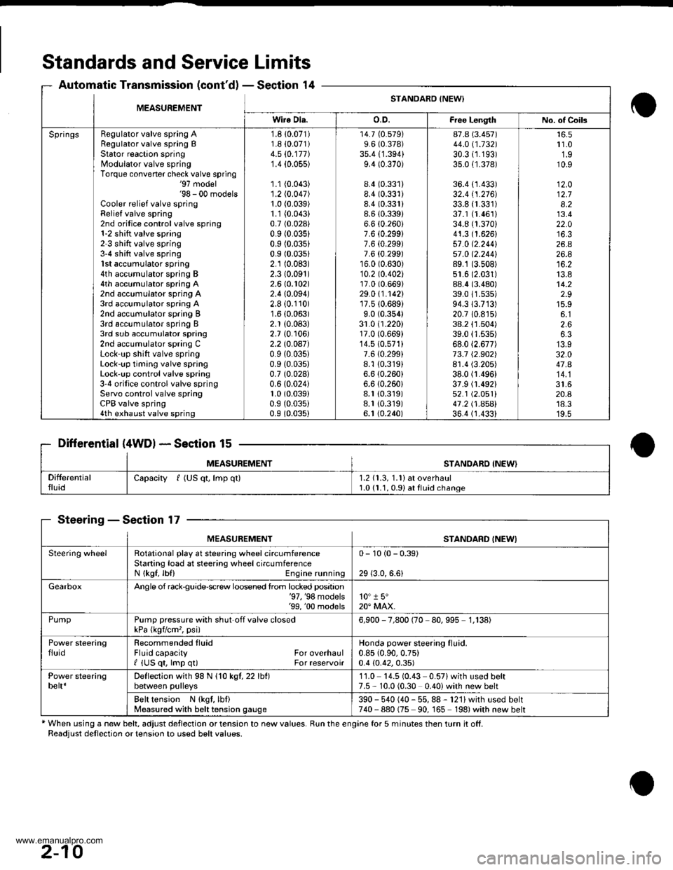
Standards and Service Limits
Automatic Transmission (cont'dl - Section 14
Differential (4WDl * Section 15
MEASUREMENTSTANOABD {NEW'
SteeringSection 17
* When using a new belt, adjust deflection or tension to new values. Run the engine for 5 minutes then turn it off.Readjust dellection or tension to used belt values.
MEASUREMENTSTANDARO INEWI
Wire Dia.o.D.Fiee LengthNo. of Coils
SpringsRegulator valve spring ARegulator valve spring BStator reaction springModulator valve springTorque convener check valve spring'97 model'98 - 00 modelsCooler relief valve springRelief valve spring2nd orilice control valve spring1-2 shitt valve spring2 3 shift valve spring3-4 shift valve spring1st accumulator spring4th accumulator spring B4th accumulator spring A2nd accumulator spring A3rd accumulator spring A2nd accumulator spring B3rd accumulator spring I3rd sub accumulator spring2nd accumulator spring CLock-up shift valve springLock-up timing valve springLock'up control valve spring3'4 orifice control valve springServo control valve springCPB valve spring4th exhaust valve spring
1.8 10.071)1.8 i0.071)4.5 (0.177)
1.4 {0.055)
1.1 (0.043)
1.2 (0.047)
1.0 (0.039)
1.1 (0.043)
0.7 (0.028)
0.9 (0.035)
0.9 (0.035)
0.9 (0.03s1
2.1 (0.083)
2.3 (0.091)
2.6 (0.102)
2.410.094)2.8 (0.110)
1.6 (0.063)
2.1 (0.083)
2.7 {0. r06)2.2lO.OA7)0.9 (0.035)
0.9 (0.035)
0.7 (0.028)
0.6 (0.024)
1.0 (0.039)
0.9 (0.035)
0.9 (0.035)
14.7 (0.579)
9.6 (0.378)
35.4 {1.394}9.4 (0.370)
8.4 (0.331)
8.4 (0.331)
8.4 (0.331)
8.6 (0.3391
6.6 (0.260i
7.6 {0.299}7.6 {0.299)7.6 {0.299)16.0 (0.630)
10.2 to.402l17.0 (0.669)
29.0 \1.1421'r7.510.689)
9.0 (0.354)
31.0 (1.220)17.0 (0.669)
14.510.571)7.610.299i8.1 {0.319}6.6 (0.260)
6.6 (0.260i
8.1 (0.319)
8.1 {0.319)6. t (0.240)
87.8 (3.457)
44.011.132130.31r.193)35.0 {1.378)
36.4 {1.433)32.4 tl.216J33.8 {r.331)37.1 (1.461)
34.8 (1.370)
41.3 (1.626)
57 .0 (2.2441
57 .0 12.244189.1 (3.508)
51.6 (2.031)
88.4 (3.480)
39.011.s35)94.313.713)20.7 10.8r5)38.2 (1.504)
39.0 (1.535)
68.0 (2.677)
73.7 12.902)8r.4 (3.205)
38.0 fl.496)37.9 (1.492)
52.1 (2.051)
41 .2 t .A5Al36.4 (1.4331
r 1.01.910.9
12.O12.78.213.422.0
26.426.8
13.814.22.915.9
2.66.3
32.047.A
20.8'18.3'19.5
Capacity f (US qt, lmp ql)1.2 (1.3, 1.1) at overhaul1.0 (1.1, 0.91 at fluid change
MEASUREMENTSTANDARD INEWI
Steering wheelRotational play at steering wheel circumferenceStaning load at steering wheelcircumferenceN {kgf, lbl) Engine running
0- 10 (0 - 0.39)
29 (3.0,6.6)
GearboxAngle of rack$uide-screw loosened lrom locked position'97, '98 models'99, '00 models10" 1 5"20" MAX.
PumpPump pressure with shut off valve closedkPa (kgvcm,, psi)6,900 - 7,800 (70 80,995 1,138)
Power steeringfluidRecommended tluidFluid capacity For overhaulI {US qt, lmp q0 For reservoir
Honda power steering fluid.0.85 (0.90,0.75)
0.4 {0.42,0.35)
Power steeringbelt*Deflection with 98 N {1O kgl,22lht)between pulleys11.0 14.5 (0.43 0.57)with used belt7.5 - 10.0 (0.30 0.40) with new belt
Belt tension N {kgt, lbf}Measured with belt tension gauge390 - 540 (40 - 55, 88 - 121) with used belt740-880 (75 90, 165 198)with new belt
2-10
www.emanualpro.com
Page 38 of 1395

--
-
METRICITEMENGLISHNOTES
AIR CONDITIONINGCooling capacity3,520 Kcal/h j 14,000 BTU/h
Compressor Type/manutacturerNo. of cylinderCaPacityMax. speedLubricant capacityLubricant type
Scroll/KElHlN
85.7 mf/rev | 5.23 cu'in/rev10,000 rpm130mf 1 algIlozsP-10
Condenser TypeCorrugated fin
Evaporator TypeCorrugated fin
Blower TypeMotor inputSpeed controlMax. capacity
Sirocco fan200 w 112 v4-Speeo440 m3/h 15,500 cu fvh
Temperature control
Compressor clutch TypePower consumptionDry, single plate, poly-V-belt drive40 W max./12 VAt 68'F (20 C)
Befrigerant TypeOuantity
HFC-134a 1R-134a)zoo o' g 24j an oz
STEERING SYSTEMTypeOverall ratioTurns, lock to lockSteering wheel diameter
Power assisted, rack and pinion
SUSPENSIONType Front
Bear
Shock absorber Front and Rear
Independent double wishbone, coil springwith stabilizerIndependent double wishbone, coil springwith stabilizerTelescopic, hydraulic nitrogen gas tilled
WHEEL ALIGNMENTCamber
CasterTotaltoe
FronthearFrontFrontRear0inln 1/16 in0mmln2mm
0'- r"00'2.10'�
BRAKE SYSTEMTvpe
Pad surface areaLining surface areaParking brake
Front
RearFrontRearTvpe
Power-assisted selt-ad,ustingventilated discPower assisted self-adiusting drum49 cm, x 2 7.6 sq-in x 273 cm, x2 11.3 sq-in x 2Mechanical actuating, rear two wheel brakes
Drum brake
TIRESize and pressureSee tire inlormation label.
ELECTRICALBafteryStarterAlternator
In under-dash fuse/relay boxIn under hood fuse/relay box
In underhood ABS fuse/relay boxHeadlightsFront turn signal lights
Front parking lightsFront side marker lightsRear side marker lightsRear turn signal lightsErake/parking lightsBack-up lightsCeiling lights {fronvrear)License plate lightSpotlightsHigh mount brake lightlgnition key lightAshtray lightGauge lightsIndicator lightslllLrmination and pilot IightsHeater illumination lights
12 V, 36 AH/s HR12V 1.0, 1.1 kW12V 100A
7.5 A, 10 A, 15 A, 20 A7.5 A, 10 A, 15 A, 20 A, 30 A, 40 A'100 A7.5 4,20 A. 40 A12V 60/55 W12 V- 21 W ('97 model),12 V - 27 W ('98-00 models)12V 5 W {'97 model),3 CP ('98 - 00 models)12V-8W12 V,3 CP12V-21W12 V 2115 W12V 21 CP (18 W)12V-8W12V-8W12V-5W12V -21W
12 V- 1.4 W12V 1.4 W12 V 1.4 W,3 W,3.4 W12V-0.84W, 1.12 W, 1.4 W,3 W, LED12 V - 0.84 W, 1.4 W, LED12 V,1.4 W
2-13
www.emanualpro.com
Page 102 of 1395
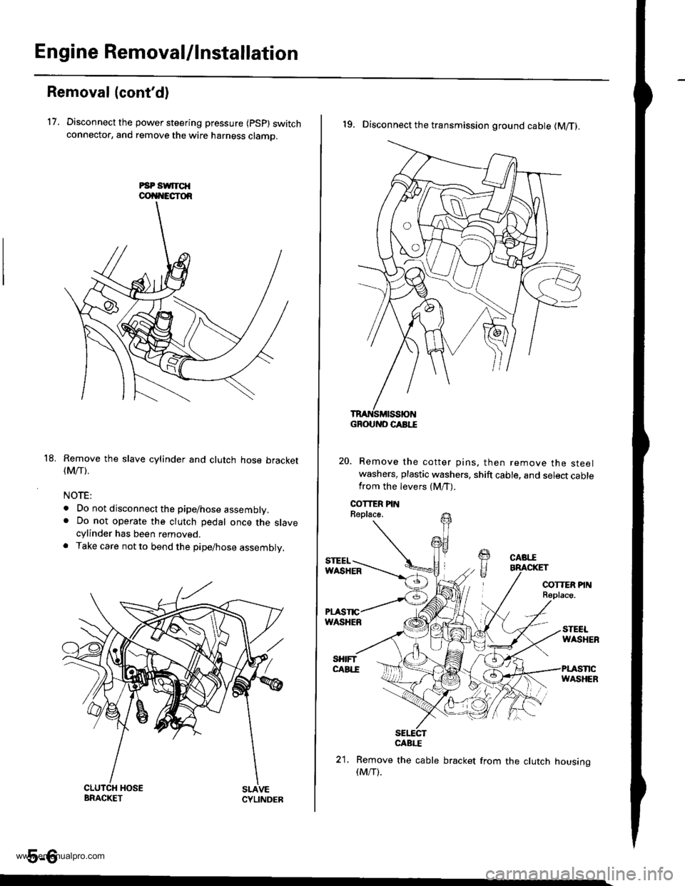
Engine Removal/lnstallation
Removal (cont'd)
17. Disconnect the power steering pressure {psp} switchconnector, and remove the wire harness clamo.
Remove the slave cylinder and clutch hose bracket(Mrr).
NOTE:
. Do not disconnect the pipe/hose assembly.. Do not operate the clutch pedal once the slavecylinder has been removed.. Take care not to bend the pipe/hose assembly.
5-6
18.
19. Disconnect the transmission ground cable (M/T).
Remove the cotter pins, then remove the steelwashers, plastic washers, shift cable, and select cablefrom the levers (M/T).
sElEcrCABI."E
21. Remove the cable bracket from the clutch housing(M/T).
GROUND CABI."E
www.emanualpro.com
Page 123 of 1395
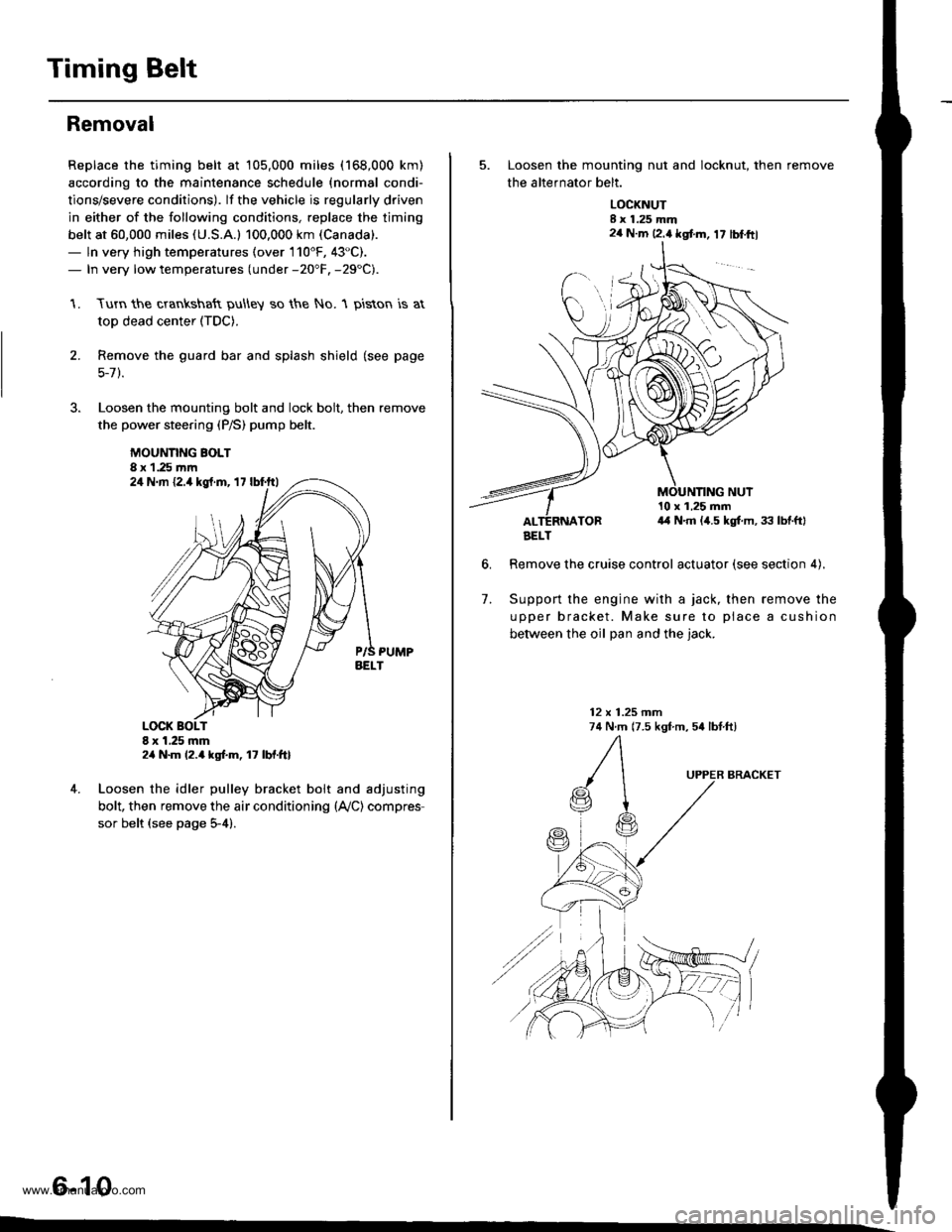
Timing Belt
Removal
Replace the timing belt at 105,000 miles (168,000 km)
according to the maintenance schedule {normal condi-
tions/severe conditions). lf the vehicle is regularly driven
in either of the following conditions, replace the timing
belt at 60,000 miles (U.S.A.l 100.000 km (Canada).
- ln very high temperatures (over 110'F, 43"C).- In very low temperatures (under -20"F. -29"C).
Turn the crankshaft pu\ley so the No. 1 piston is at
top dead center (TDC).
Remove the guard bar and splash shield (see page
5-7 ).
Loosen the mounting bolt and lock bolt. then remove
the power steering (P/S) pump belt.
MOUNNNG BOLT8 x 1.25 rnm
1.
2.
,l
4. Loosen the idler pulley bracket bolt and adjusting
bolt, then remove the air conditioning (lVC) compres
sor belt (see page 5-4).
6-10
24 N.m {2.4 kgt.m, 17 lbf.ftl
24 N.m 12.4 kgf.m, lt lbf.ftl
5. Loosen the mounting nut and locknut, then remove
the altefnator belt.
LOCKNUTI x 1.25 mm2a N.m 12.4 kgt m, 17 lblftl
6.
10 x 1,25 mm4,1 N.m (,1.5 kgt m, 33 lbtftl
Remove the cruise control actuator (see section 4).
Support the engine with a jack, then remove the
upper bracket. Make sure to place a cushion
between the oil Dan and the iack.
12 x 1.25 mm74 N.m (7.5 kgf m, 54 lbtftl
7.
BRACKET
AELT
www.emanualpro.com
Page 129 of 1395
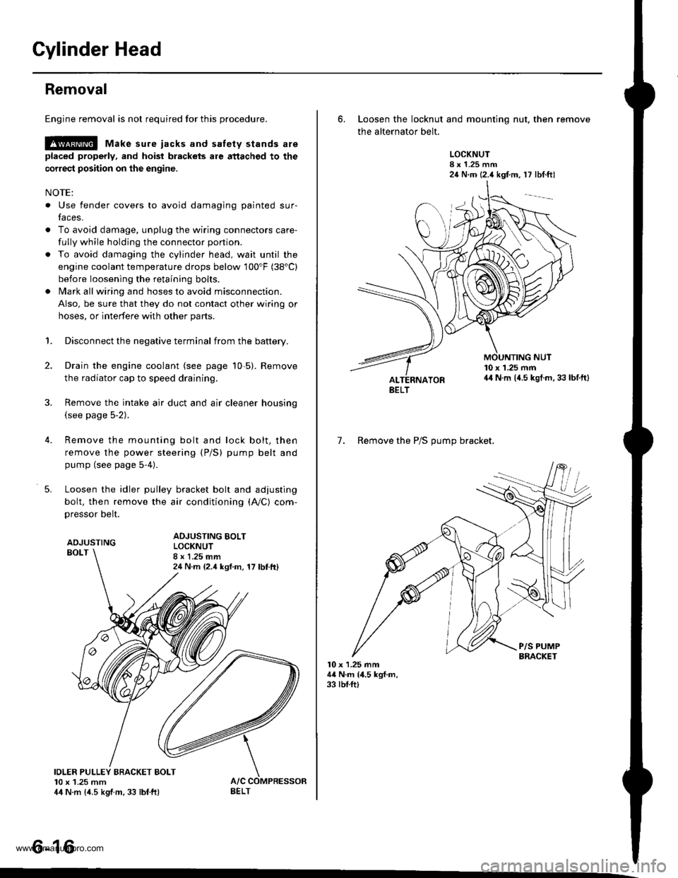
Gylinder Head
Removal
Engine removal is not required for this procedure.
l!@ Make sure iacks and safety stands are
placed properly, and hoist blackels ale attachgd to the
correct position on the engine.
NOTE:
o Use fender covers to avoid damaging painted sur-
faces.
o To avoid damage, unplug the wiring connectors care-
fully while holding the connector portion.
. To avoid damaging the cylinder head, wait until the
engine coolant temperature drops below 100"F (38'C)
before loosening the retaining bolts.
. Mark all wiring and hoses to avoid misconnection.
Also, be sure that they do not contact other wiring or
hoses, or interfere with other parts.
2.
4.
5.
1.Disconnect the negative terminal from the battery.
Drain the engine coolant (see page 10-5). Remove
the radiator cap to speed draining.
Remove the intake air duct and air cleaner housing(see page 5-2).
Remove the mounting bolt and lock bolt, then
remove the power steering (P/S) pump belt and
pump (see page 5-4).
Loosen the idler pulley bracket bolt and adjusting
bolt, then remove the air conditioning (A,/C) com,
pressor belt.
ADJUSTINGBOLT
ADJUSTING BOLTLOCKNUT8 x 1.25 mm24 N m {2.4 ksf.m, 17 lbttt}
IOLER PULLEY BBACKET BOLT10 x 1.25 mm44 N.m {4.5 kgtm, 33 lbf ft)
tt aAo-Io
6. Loosen the locknut and mounting nut, then remove
the alternator belt.
LOCKNUT8 x 1.25 mm24 N.m (2.4 kgf.m, 17 lbt.ftl
10 x 1.25 mm44 N.m (4.5 kgt.m. 33 lbf.ft)
7. Remove the P/S OUmo bracket.
l0 x 1.25 mm44 N.m (4.5 kgf.m,33 rbf.ft)
BELT
www.emanualpro.com
Page 384 of 1395
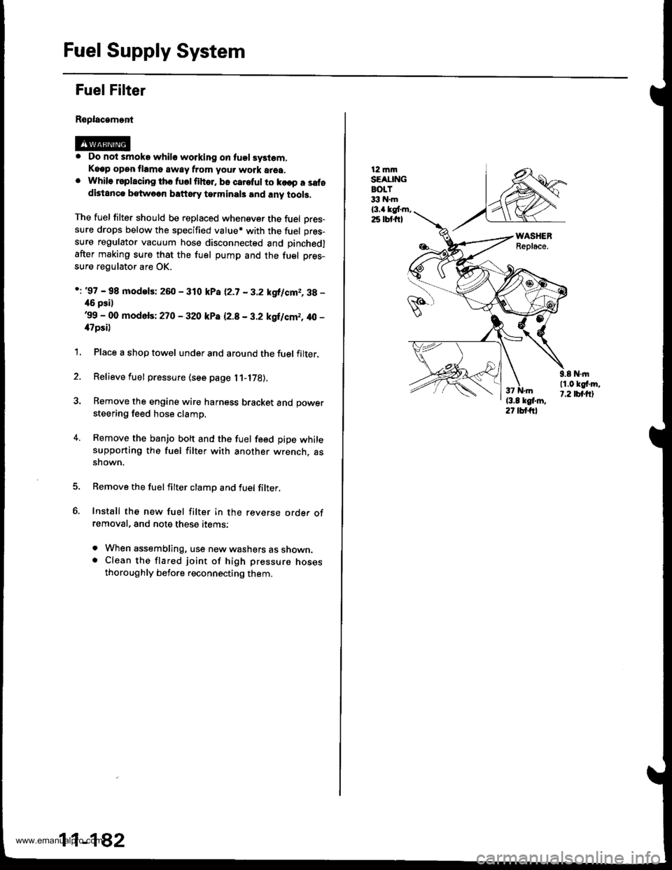
Fuel Supply System
Fuel Filter
Replacamont
. Do not smoke whilo working on tuol syslom,Keep open flame away from your work area.. While rsplscing ths fuolfihor. bo careful to ko€p a safedistanca betweon baftsry tarminals and any tools,
The fuel filter should be replaced whenever the fuel Dres-sure drops below the specified value* with the fuel pres-
sure regulator vacuum hose disconnected and pinchedl
after making sure that the fuel pump and the fuel pres-
sure regulator are OK.
i: '97 - 98 modelsi 260 - 310 kPa 12.7 - 3.2 kgllcm2,3g -
46 psil'99 - 00 mod6fs: 270 - 320 kP8 12.8 - 3.2 kgilcm2, 40 -
il7psi)
1, Place a shop towel under and around the fuel filter.
2. Relieve fuel pressure (see page l1-l7B).
3. Remove the engine wire harness bracket and power
steering feed hose clamp.
4. Remove the banjo bolt and the fuel feed pipe whilesupporting the fuel filter with another wrench. assnown.
Remove the fuelfilter clamp and fuel filter,
Install the new fuel filter in the reverse orde. ofremoval, and note these items:
. When assembling, use new washers as shown.. Clean the flared joint of high pressure nosesthoroughly before reconnecting them.
11-182
12 mmSEAUNGBOLT33 hl.m
l3.a kgt m,25 lbt frl
9.8 N.|n11.0 kgf'm,t.2 tbt.ftl
www.emanualpro.com
Page 666 of 1395
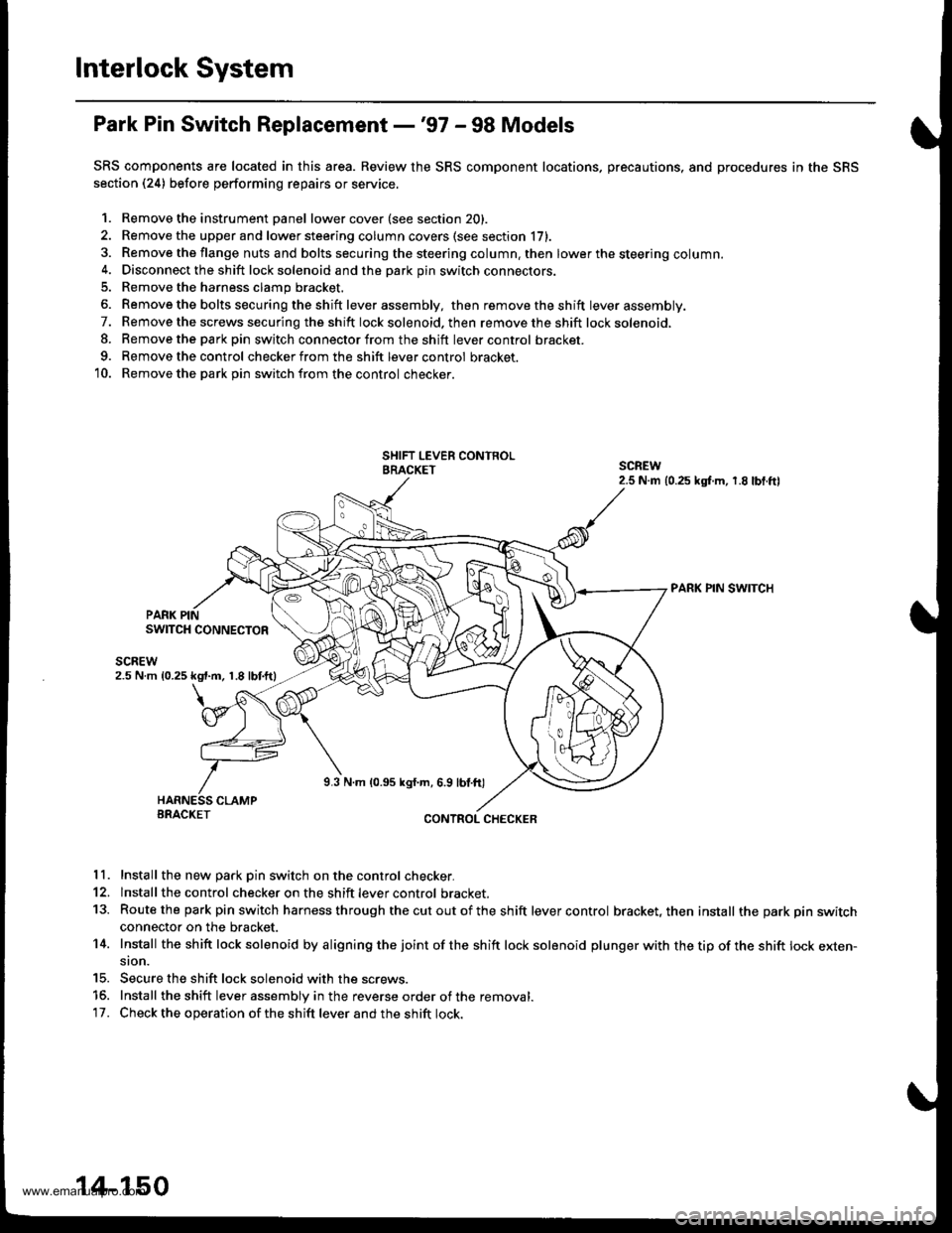
Interlock System
Park Pin Switch Replacement -'97 - 98 Models
SRS components are located in this area. Review the SRS component locations, precautions, and procedures in the SRS
section (24) before performing repairs or service.
1. Remove the instrument Danel lower cover (see section 20).
2. Remove the upper and lower steering column covers (see section li,.
3. Remove the flange nuts and bolts securing the steering column. then lower the steering column.4. Disconnect the shift lock solenoid and the park pin switch connectors.
5. Remove the harness clamp bracket.
6. Remove the bolts secu ring the shift lever assembly, then removetheshift lever assembly.
7. Remove the screws securing the shift lock solenoid. then remove the shift lock solenoid,
8. Remove the parkpin switch connector from the shift lever control bracket.
9. Remove the control checker from the shift lever control bracket.
10. Remove the park Din switch from the control checker.
PARK PIN SWITCH
PARK PINSWITCH CONNECTOR
scnEw2.5 N m 10.25 kgt.m, 1.8 lbtftl
9.3 N.m 10.95 kgf.m, 6.9 lbl.ft)
BRACKETCONTROL CHECKER
11. Install the new Dark Din switch on the control checker.
12. lnstall the control checker on the shift lever control bracket.
13. Routethe park pin switch harness through thecutoutofthe shift lever control bracket, then install the park pin switchconnector on the bracket.
14. Install the sh ift lock solenoid by a ligning the joint of the sh ift lock solenoid plu nger with the tip of the shift lock exten-sion.
15. Secure the shift lock solenoid with the screws.
15. Install the shift lever assembly in the reverse order of the removal.'17. Check the operation of the shift lever and the shift lock.
14-150
www.emanualpro.com
Page 667 of 1395
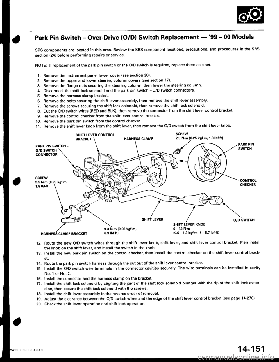
Park Pin Switch - Over-Drive (O/Dl Switch Replacement -'99 - 00 Models
SRS components are located in this area. Review the SRS component locations, precautions, and procedures in the SRS
section {24) before performing repairs or service.
NOTE: lf replacement of the park pin switch or the O/D switch is required. replace them as a set.
1. Remove the instrument panel lowercover(see section 20).
2. Remove the upper and lower steering column covers (see section 17).
3. Remove the flange nuts securing the steering column. then lower the steering column.
4. Disconnect the shift lock solenoid and the park pin switch - O/D switch connectors
5. Remove the harness clamp bracket.
6. Remove the bolts securing the shift lever assembly, then remove the shift lever assembly.
7. Remove the screws securing the shift lock solenoid, then remove the shift lock solenoid.
8. Cut the O/D switch wires (REDand BLK),then remove the con nector from the shift lever control bracket
9. Remove the control checker from theshift lever control bracket
10. Remove the oark oin switch from the control checker.
11. Remove the shift lever knob from the shift lever, then remove the O/D switch from the shift lever knob.
SCREW2.5 N.m 10.25 kgtm, 1.8lbf,ft)SHIFT LEVER CONTROLBRACKET
PARK PIN SWITCH -
o/D swlTcHCONNECTOR
2.5 N.m (0.25 kgt m,1.8 tbf.fr)
HABNESS CLAMP BRACKET
9.3 N.m 10.95 kgl.m.6.9 tbf ft)
SHIFT LEVER KNOB6-12N,m{0.6 - 1.2 kgt.m.4 - 8.7 lbf ftl
SHIFT LEVERo/o swlTcH
12. Route the new O/D switch wires through the shift lever knob, shift lever, and shift lever control bracket, then install
the knob on the shift lever, and install the switch in the knob.
13. Install the new park pin switch on the control checker, then install the control checker on the shift lever control brack-
et.
14. Routethe parkpin switch harnessthroughthecutoutoftheshift lever control bracket.
15. Install the O/D switch wire terminals in the connector cavities securely. The wire terminals can be installed in cavity
No. 1 or No.2.
16, Install the connector and the harness clamp on the bracket.
17. tnstall the shift lock solenoid by aligning the joint ot the shift lock solenoid plu nger with the tip of the shift lock exten-
sion, then secure the shift lock solenoid with the screws,
18. lnstall the shift lever assemblv inthe reverse order of removal.
19. Adjust the clearance between the O/D switch wires and the edge of the sh ift lever control bracket (see page 14-270).
20. Check the shift lever operation and shift lock operation.
14-151
www.emanualpro.com
Page 786 of 1395
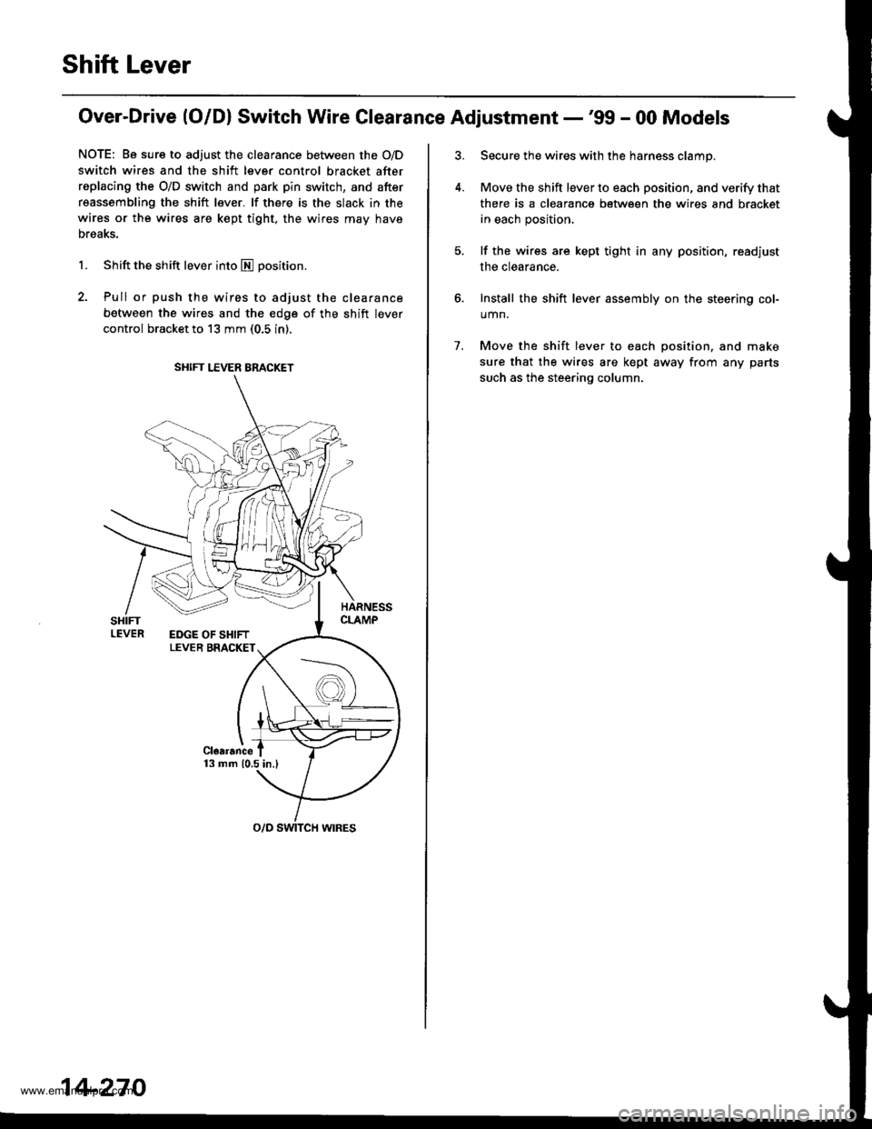
Shift Lever
Over-Drive (O/Dl Switch Wire Clearance Adjustment -'99 - 00 Models
NOTE: Be sure to adjust the clearance between the O/D
switch wires and the shift lever control bracket after
replacing the O/D switch and park pin switch, and after
reassembling the shift lever. lf there is the slack in the
wires or the wires are kept tight, the wires may have
Dreaks.
1. Shift the shift lever into E positron.
2. Pull or push the wires to adjust the clearance
between the wires and the edge of the shift lever
control bracket to 13 mm (0.5 in).
SHIFT LEVER BRACKET
14-270
7.
Secure the wires with the harness clamp.
Move the shift lever to each position, and verify that
there is a clearance between the wires and bracket
in each position.
lf the wires are kept tight in any position, read.iust
the clearance.
Install the shift lever assembly on the steering col-
umn.
Move the shift lever to each position, and make
sure that the wires are kept away from any parts
such as the steering column.
www.emanualpro.com
Page 846 of 1395

Steering
Special Toofs ............. 17-2
Component Locations
Index ................ ....... 17-3
Troubleshooting
General Troubleshooting ................ 1 7-4
Noise and Vibration ......................... 17-8
Fluid Leaks ............. 17-10
Inspection and Adiustment
Steering Operation .......................... 17-12
Power Assist Check
With Vehicle Parked ....................
Steering Linkage and Gearbox .......
Pump Belt
Rack Guide Adjustment ...................
Fluid Rep|acement ...................,,.,....
Pump Pressure Check .................,,...
*Steering Wheel
Removal ................. 17-18
*Steering Column
Removal/lnstallation ................ ....... 17 -2O
lnspection .............. 17-21
Steering Lock Replacement ............ 17 -22
Power Steering Hoses, Lines
Ffuid Leakage Inspection ................. 17 -23
Repfacement .......... 17-23
Power Steering Pump
Repfacement .......... 17-24
Disassembly ...........17-25
fnspection .............. 17-26
Reassembly ............ 17-28
Power Steering Gearbox
Removal ................. 17-31
Disassembly ........... 17-34
Reassembly ............ 17-40
Ball Joint Boot Replacement .......... 17-50
Installation ............. 17-51
17-12
17-13
17-14
l7-15
17-15
17-16
Disassembly/Reassembly............... 17-18
4'%/b.......... -r'-7--a/
SUPPLEN\EN AL RES\RA(N SYSTES{ (SRS\
This model has an SRS which includes a driver's airbag in the steering wheel hub. a passenger's airbag in the dashboardabove the glove box ('97 - 00 models), and seat belt tensioners in the seat belt retractors ('98 - 00 models). Informationnecessary to safely service the SRS is included in this Service Manual. ltems marked with an asterisk (*) on the contentspage include, or are located near, SBS components. Servicing. disassembling or replacing these items will require specialprecautions and tools, and should only be done by an authorized Honda oearer.
To avoid rendering the SRS inoperative, which could lead to peFonal iniury or death in the event of a sevore trontalcollision. allSRS service work must be performod by an authorized Honda dealer.lmproper service procedurgs, including incorrect removal and installalion of the SRS, could lead to personal iniurycaused by unintontional deployment of th€ airbags {'97 - 00 models), and seat belt tensioners ('98 - 00 modelsl.Do not bump the SRS unit. Otherwise, the system may lail in case ot a collision, or the airbags may deploy when theignition switch is ON (lll.
SRS electrical wiring harnesses are identitied by yellow colof coding. Ralated components are located in the steeringcolumn, front console, dashboard, dashboard lower panel, and in the dashboard above the glove box. Do not use elec-trical test equipment on these cilcuits,
www.emanualpro.com