sensor HONDA CR-V 2000 RD1-RD3 / 1.G Owners Manual
[x] Cancel search | Manufacturer: HONDA, Model Year: 2000, Model line: CR-V, Model: HONDA CR-V 2000 RD1-RD3 / 1.GPages: 1395, PDF Size: 35.62 MB
Page 339 of 1395
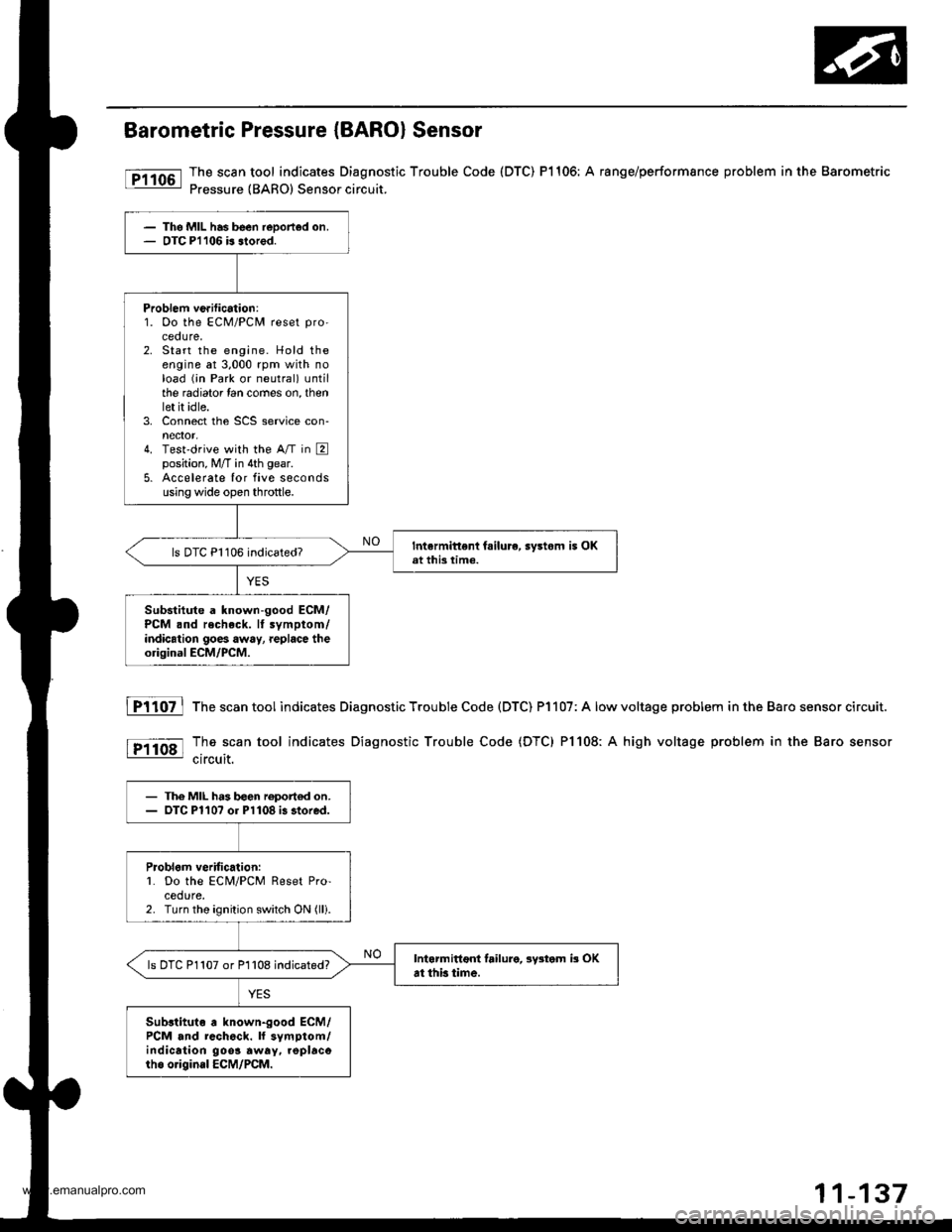
Barometric Pressure (BARO) Sensor
The scan tool indicates Diagnostic Trouble Code (DTC) P1106: A range/performsnce problem in the Barometric
Pressure {BARO) Sensor circuit.
The MIL has been reDorted on.OTC Pl106 b slored.
Problem ve.ification:1. Oo the ECM/PCM reset pro'
ceoure.2. Start the engine. Hold theengine at 3,000 rpm with noload (;n Park or neutral) untilthe radiator lan comes on, thenlet it idle.3. Connect the SCS service con-nector,4. Test'drive with the A/T in Eposition, M/T in 4th gear.
5. Accelerate Ior five secondsusing wide open throttle.
Intermittent fsilure, sy3tom i5 OKat this time.ls DTC P1106 indicated?
Substitute a known-good ECM/PCM .nd recheck. It symptom/indication goes away, replace theorigioal ECM/PCM.
fTiloz l
tP11o8l
The scan tool indicates Diagnostic Trouble Code (DTC) P1107: A low
The scan tool indicates Diagnostic Trouble Code (DTC) Pl108: A
circuit.
voltage problem in the Baro sensor circuit.
high voltage problem in the Baro sensor
- The MIL h.3 b€en roport€d on.- OTC Pl10? or Pl108 i3 stored.
Problom veritic.lion:L Do the ECM/PCM Reset Pro-cedure.2. Turn the ignition switch ON (lli.
Intarmittoni failure, lystom b OKat thb time.ls DTC P1107 or P1108 indicated?
Sub3tituto a known-good ECM/PCM and rcch6ck. ll symptom/indication 9oo3 away. .oplacorho o.igin.l ECM/PCM.
www.emanualpro.com
Page 342 of 1395
PGM-FI System
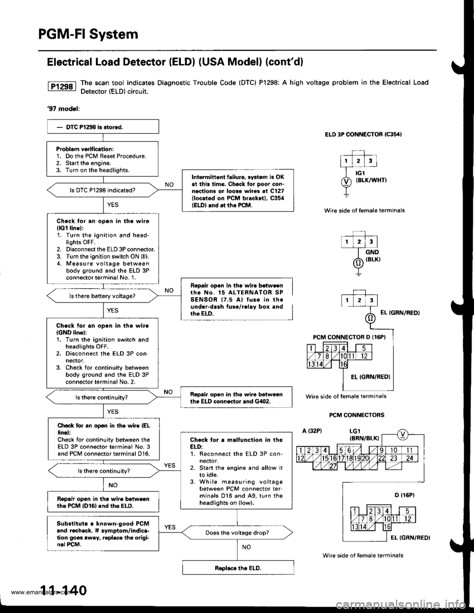
Electrical Load Detestor (ELDI (USA Model) (cont'dl
The scan tool indicates Diagnostic Trouble Code {DTC) Pl298; A high voltage problem in the Electrical Load
Detector (ELD) circuit.
97 modsl:
ELD 3P CONNECTOR {C35,'I
Wire sido oI lemale terminals
r lzlrl--T_ow
/6 IBLKI
Y
Repail op€n in th. wire b€tws€ntho No. 15 ALTERNATOR SPSENSOR 17.5 A) tuse in theunder-dlrh fuso/r.lay box andth6 ELD.EL {GRN/NEDI
PCM CONNECTORS
Problam verification:1. Do the PCM Reset Procedure.2. Start the engine.3. Turn on the headlights.Intermittent tailuro, systcm is OK.t this time. Chack for ooor con-noction! or looro wire3 at C127{locaied on PCM brackot), C35{{ELDI and .t tho PCM.
Chack for an opan in tho wilellGl linol:1. Turn thg ignition and head-lights OFF.2. Disconnect the ELD 3P connector.3. Turn the ignition switch ON {ll).4. M6asure voltage b€tw€enbody ground and the ELD 3Pconnoctor terminal No. 1.
Chock lol !n open in the wireIGND linel:'1. Turn the ignition switch andheadlights OFF.2. Disconnect the ELD 3P conneqor,3. Check for continuity betweenbody ground and the ELD 3Pconnector terminal No. 2.
Ropair opon in th6 wi.e betweonth. ELD connector rnd GiO2,
Ch.ck lo. an open in th€ wiro (EL
line):Check for continuity between theELD 3P connector terminal No. 3and PCM connector terminal 016.
Chock for . malfunction in theELD:1. Reconnect the ELD 3P con-neclor,2. Start the engine and allow itto idle.3. While measuring voltagebetween PCM connector terminals 016 and A9. turn theheadlights on (low).
ls there continuityT
R6pafu op6n in tho wire betweenthe PCM {D161snd th6 ELD.
Subltituto . known-good PCMand rachock, f symptom/indic.-tion goes awry, ropl.ce the origi-n.l PCM.
Does the voltage drop?
Wire side of lemale terminals
11-140
Wire side of lemale terminals
www.emanualpro.com
Page 343 of 1395
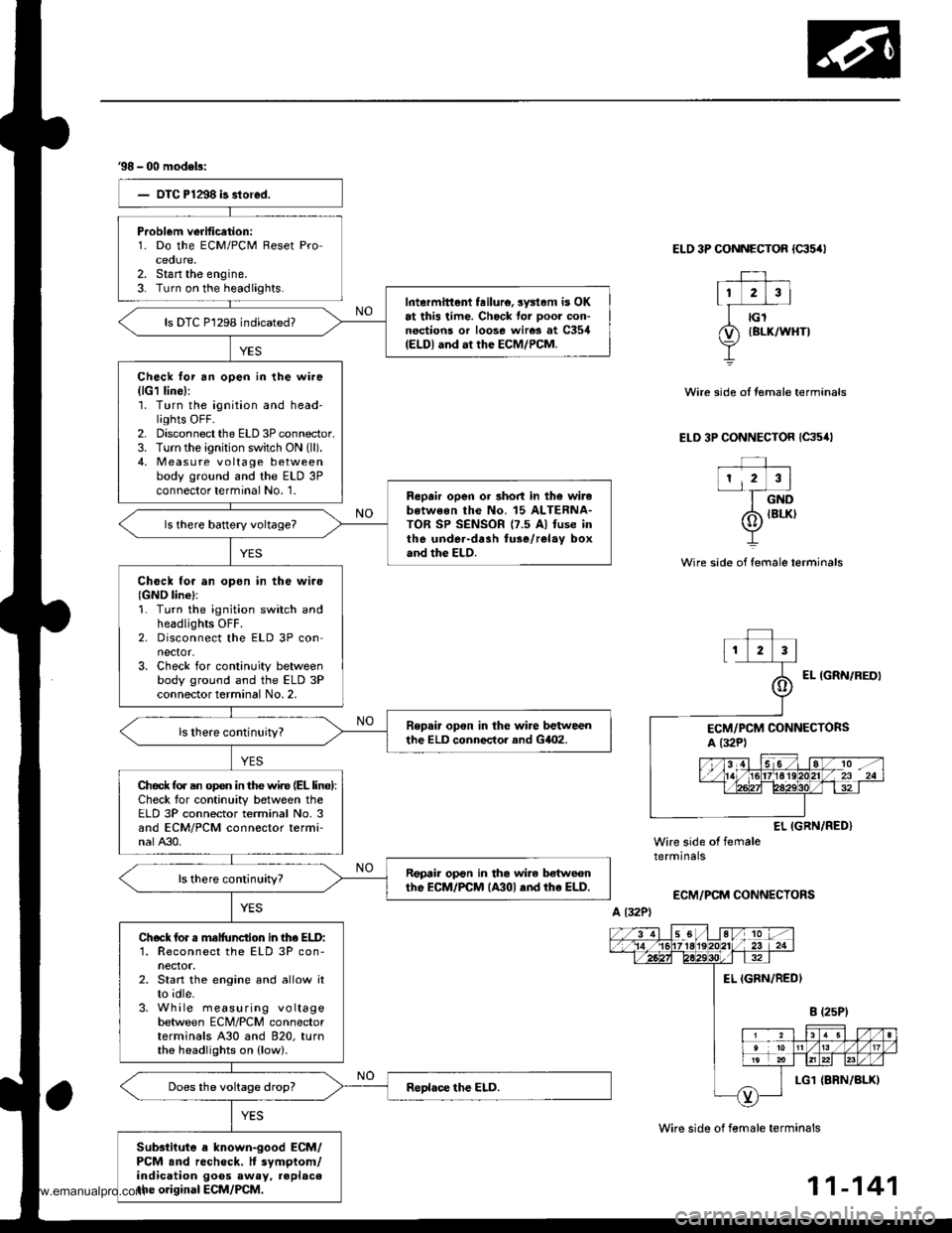
38 - 00 modeb:
Problem verification:1. Do the ECM/PCM Reset Proceoure.2. Stan the engine.3- Turn on the headlights.Intermittent feilure, sysl.m is OKat this time. Check for ooor con-nections or loose wires at C354(ELDI and at the ECM/PCM.
ls DTC P1298 indicated?
Check lor an open in the wire(lG1 line):'1. Turn the ignition and head-lights OFF.2. Disconnect the ELD 3P connector.3. Turn the ignition switch ON (ll).
4, Measu re voltage betweenbody ground and the ELD 3Pconnector terminal No. '1.Reprir open or short in th6 wirebotweon the No. 15 ALTERNA-TOR SP SENSOR {7.5 Al fuse inthe under-drah fuse/relay boxand the ELD.
Check tor an opon in tho wire{GND line}:1. Turn the ignition switch andheadlights OFF.2. Disconnect the ELD 3P connector.3. Check for continuity betweenbody ground and the ELD 3Pconnector terminal No. 2,
Repair opon in the wire betweenthe ELD conneclor and GilO2.
Ched( fo. an op€n in the wir€ (EL linel:Check for continuity between theELD 3P connector terminal No. 3and ECM/PCM connector termi-nalA30.
Repair op€n in tha wile botwecnthe EcM/PCM lA30l .nd rhe ELD.
Check for s malfunction in lhe ELD:1. Reconnect the ELD 3P con-nector.2. Start the engine and allow itto idle.3. While measuring voltagebetween ECM/PCM connectorterminals A30 and 820, turnthe headlights on (low).
Substiiute a known-good ECM/PCM and recheck. It symptom/indication goos away, replacethe original ECM/PCM.
ELO 3P CONNECTOR {c35/rl
Wire side of female terminals
Wire side of female terminals
Wire side ot temale terminals
ELD 3P CONNECTOR {C35,lt
EL IGRN/RED}Wire side of femaletermrnars
ECM/PCM CONNECTORS
A l32P)
11-141
www.emanualpro.com
Page 344 of 1395
PGM-FI System
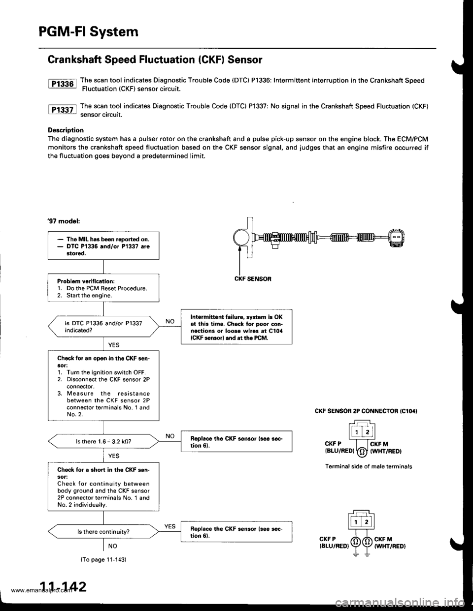
Grankshaft Speed Fluctuation (CKF) Sensor
fF13361l Tj":""l.tool indicates Diagnostic Trouble Code (DTCI P1336: Intermittent interruption inthe Crankshaft Speed: Fluctuation (CKF) sensor circuit.
The scan tool indicates Diagnostic Trouble Code (DTC) P1337: No signal in the Crankshaft Speed Fluctuation (CKF)
sensor circuit.
Description
The diagnostic system has a pulser rotor on the crankshaft and a pulse pick-up sensor on the engine block. The ECM/PCM
monitors the crankshaft speed fluctuation based on the CKF sensor signal, and judges that an engine misfire occurred if
the fluctuation goes beyond a predetermined limit.
37 mod.l:
CKF SENSOR 2P CONNECTOR IClO4I
T:]l-r'r Lll
l1 zLl''''CKF P I lcKF Mtalu/aeot fdJ twxrneor\-7
Terminal side of male terminals
(To page 11-113)
11-142
- Tho MIL ha3 been reported on.- DTC P1336 and/or P1337 arestored.
Problem verificrtion:1. Do the PCM Reset Procedure.2. Start the engine.
Intermittent {ailure, systom is OK.l thia timo. Ch6ck tor poor con-nections or loose wir$ at ClorlICKF sonsorl .nd at tho PCM.
Chock tor an opon in th6 CKF .en'30r:1. Turn the ignition switch OFF.2. Disconnect the CKF sensor 2Pconnector,3, M easure the resistancebetween the CKF sensor 2Pconnector terminals No. 'l andNo.2.
ls there 1.6-3.2 kO?
Check fo. a short in the CKF 3en-sot:Check for continuity betweenbody ground and the CKF sensor2P connector terminals No. 1 andNo.2 individually.
CKF SENSOR
www.emanualpro.com
Page 345 of 1395
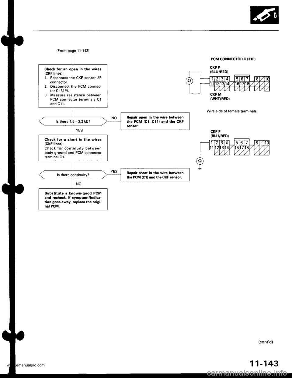
{From page 11-142)
Chock to. an open in the wires(CKF lin06l:1. Reconnect the CKF sensor 2Pconnector,2. D;sconnect the PCM connec-tor C (31P).
3. Measure resistance betweenPCM connector terminals C1and Cl1.
Ropair open in the wire betwoontho PCM lcl, Cl1l and th6 CKF!6naor.ls there 1.6 - 3.2 k0?
Chock tor a short in the wires(CKF lino3):Check for continuity betweenbody ground and PCM connectorterminalCl.
Rcoair short in thc wire b€tweenthe PCM {Cl I and the CKF .en!o..
Subsiituto r known-good PCMand r6chock. lf symptom/indica-tion goe3 away, roplaco the origi-n.l rcM.
PCM CONNECTOR C 13lPI
Wire side of lemale terminals
CKF P
IELU/REDI
(cont'd)
11-143
www.emanualpro.com
Page 346 of 1395
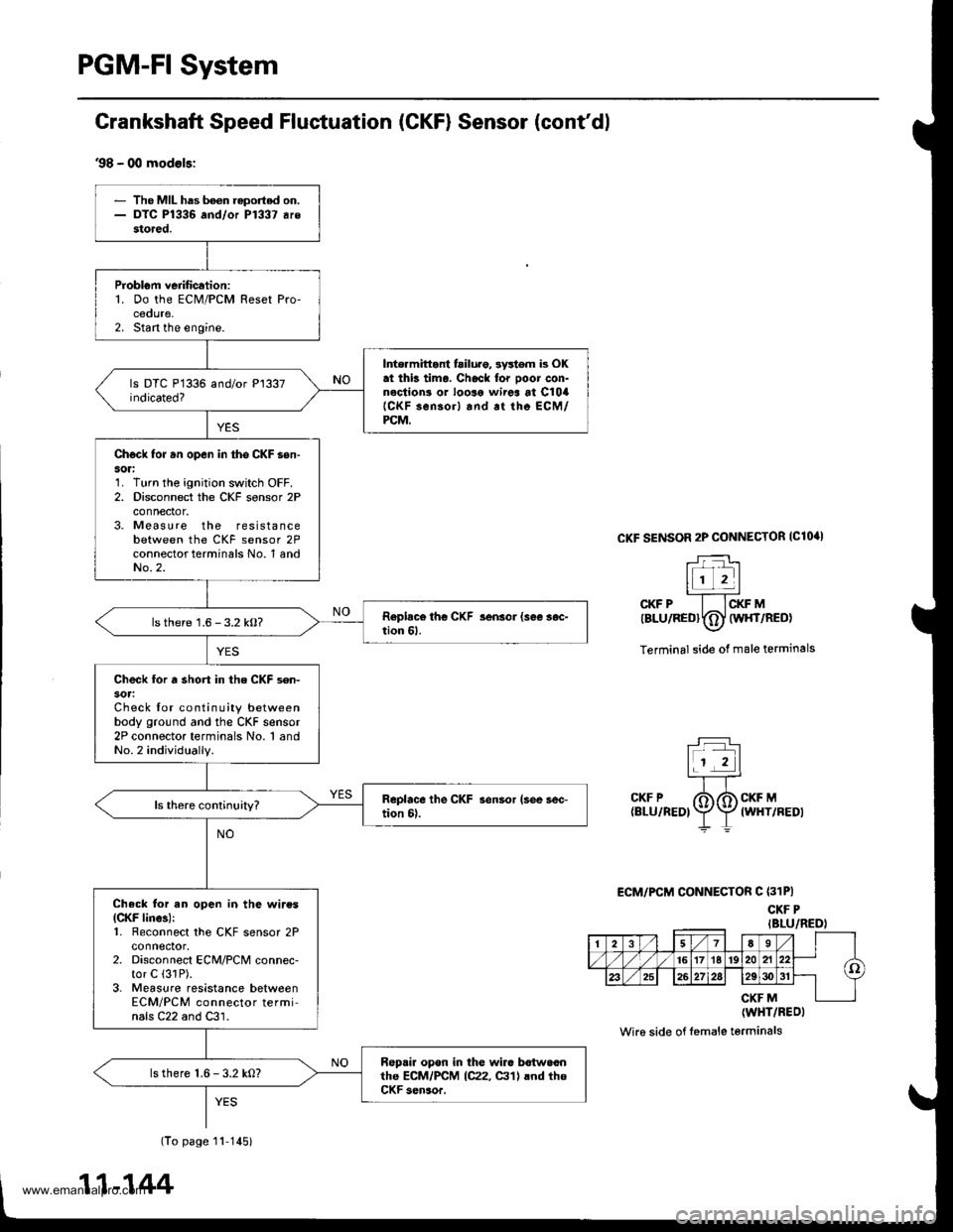
PGM-FI System
Grankshaft Speed Fluetuation (CKFI Sensor (cont'dl
.98 - 00 modols:
CKF SENSOR 2P CONNECTOR IClO'I
r-:-i-_ltr_- |l1 2ll,,-'CKF P I ICKF MtsLuneotTOl wlrrneo)\7
Terminal side of male terminals
r:l
t! El
.KFP XA"*."talu rneor \:f
f rwxvneor
ECM/PCM CONNECTOR C (31P)
CKF PIBLU/REDI
CKF M(WHT/BEOI
Wi16 side of l6male terminals
1278__l
-lI(o
T
161716't9202122
,/ 2s262728293()3l
M
- The MIL has boon reported on.- DTC P1336 and/or P1337 arestored.
ProblGm verification:1. Do the ECM/PCM Reset Pro-cedure,2. Stan the engine.
Inte.mittant failuro, 3y*om b OKat thb tima. Chack lor ooor con-nections or looso wirea at C10a{CKF sensorl and.t the ECM/PCM,
Chgck forun open in tho CKF son-sori1. Turn the ignition switch OFF.2. Disconnect the CKF sensor 2Pconnector.3. Measure the resistancebetween the CKF sensor 2Pconnector terminals No. 1 andNo.2.
lsthere 1.6 - 3.2 kO?
Check for a short in the CKF sen-
Check lor continuity betweenbody ground and the CKF sensor2P connector terminals No. 1 andNo.2 individually.
Check for an open in the wiresICKF linca):1. Feconnect the CKF sensor 2Pconnector.2. Disconnect ECM/PCM connec-tor C (31P).
3. Measure resistance betweenECM/PCM connector termi'nals C22 and C31.
Repair opon in the wir6 botwoonthe ECM/PCM 1C22, glll lnd th6CKF s6n3or.
ls there 1.6 - 3.2 kO?
(To page 11'1451
11-144
www.emanualpro.com
Page 348 of 1395
PGM-FI System
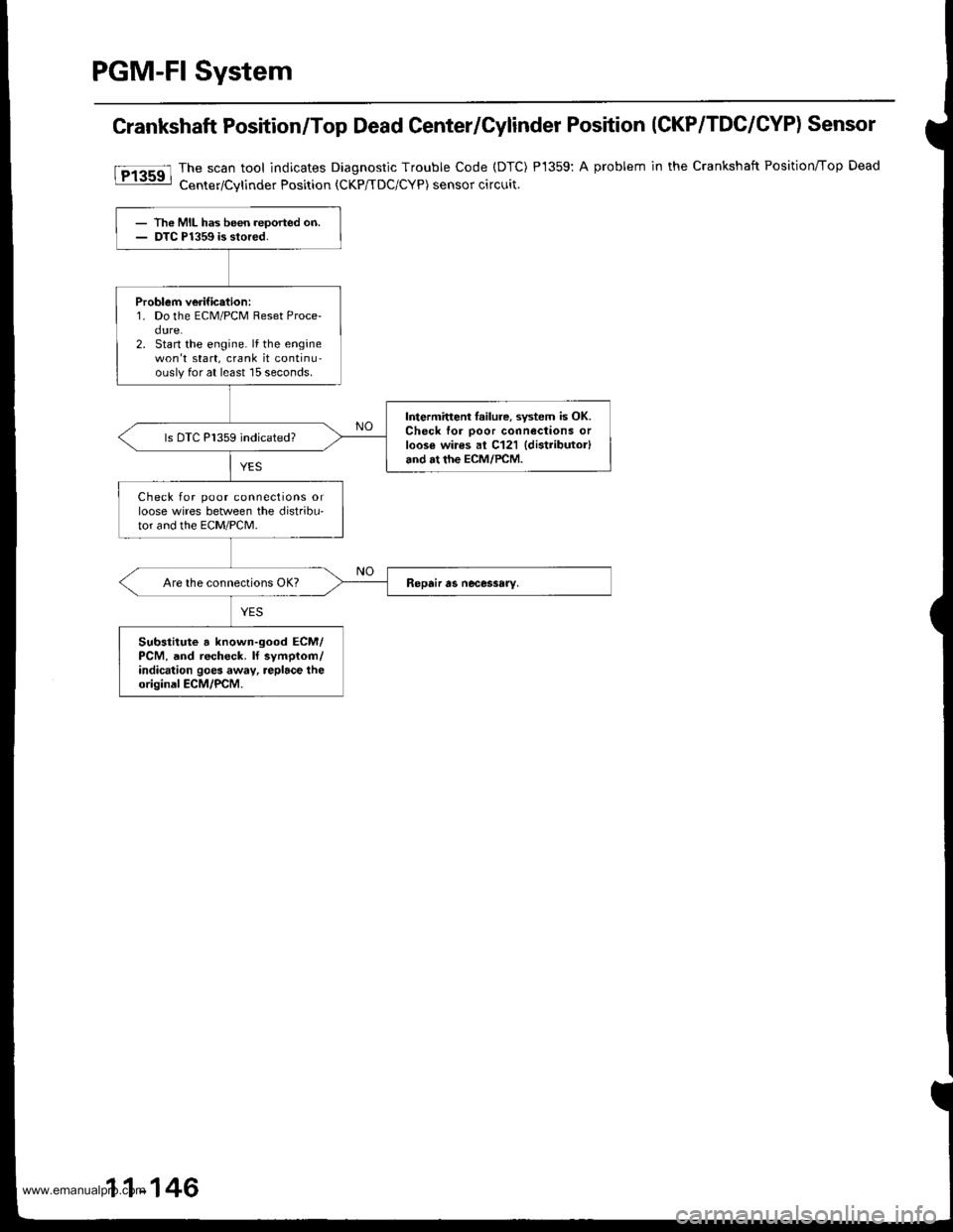
Crankshaft Position/Top Dead Center/Cylinder Position (CKP/TDC/CYP) Sensor
The scan tool indicates Diagnostic Trouble Code (DTC)
Center/Cvlinder Position tCKP/TDC/CYP) sensor circuit.
P1359:A problem in the Crankshaft Position/Top Dead
- The MIL has been reoorted on.- DTC P1359 is stored.
Problem verific.tion:1. Do the ECM/PCM Reset Proce-dure.2. Start the engine. lf the enginewon't start, crank it continu-ouslyfor at least 15 seconds.
Intermitteni lailure, system is OK.Check for ooor connections orloos€ wires al C121 {distributor}and at the ECM/PCM.
ls DTC P1359 indicated?
Check for poor connections orloose wires between the distribu'tor and the EcM/PcM.
Substitute a known-good ECM/PCM, and recheck. ll symplom/indication goes away, replace theoriginal ECM/PCM.
11-146
www.emanualpro.com
Page 350 of 1395
PGM-FI System
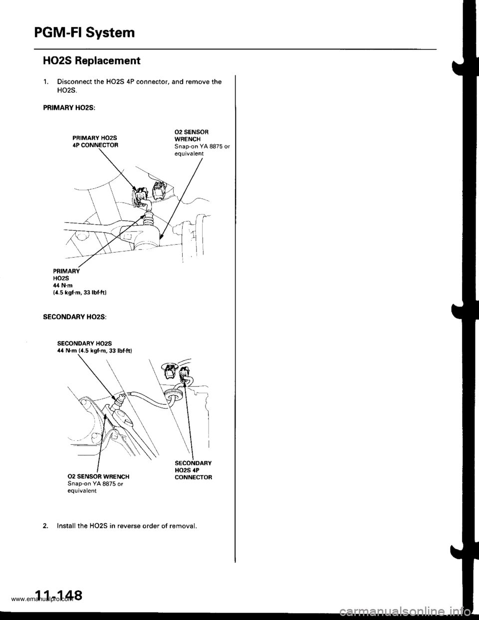
HO2S Replacement
1. Disconnect the HO2S 4P connector, and remove the
HO2S.
PRIMARY H02S:
PRIMARY HO2S4P CONNECTOR
02 SENSORWRENCH
PRIMARYHO2S44 N.m{4.5 kgt m,33lbf.ftl
SECONDARY HO2S:
SECONDARY HO2S4,0 N.m (4.5 kg{.ft, 33 lbtftl
2. Install the HO2S in reverse order of removal.
11-148
www.emanualpro.com
Page 351 of 1395
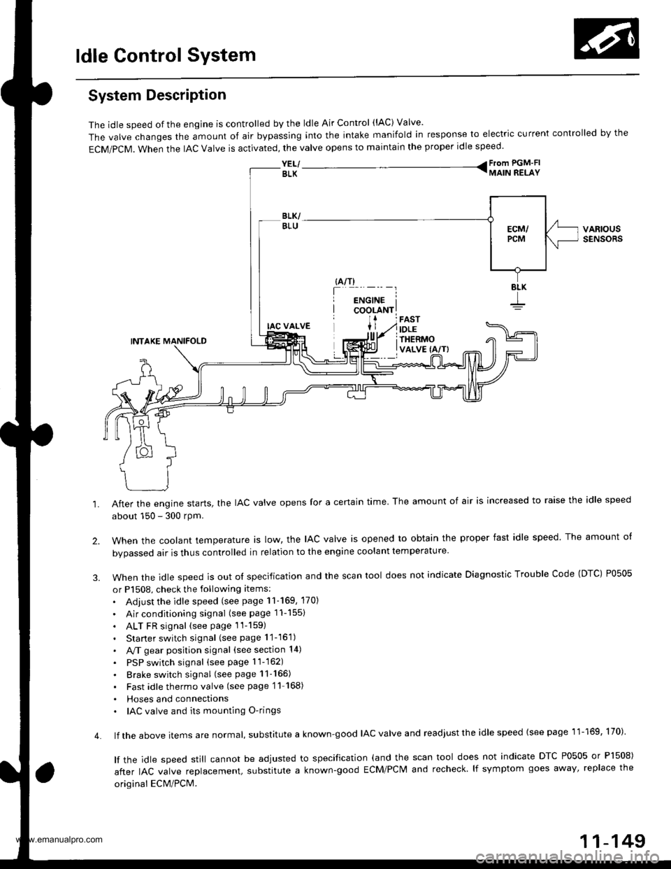
ldle Control System
System Description
The idle speed of the engjne is controlled by the ldle Air Control (lAC) Valve'
The valve changes the amount of air bypassing into the intake manifold in response to electric current controlled by the
ECM/PCM. When the lAc valve is activated, the valve opens to maintain the proper idle speed.
YEL/ From PGM'FI
BLK TMAIN RELAY
VARIOUSSENSORS
4.
IAC VALVE
INTAKE MANIFOLD
After the engine starts, the IAC valve opens for a certain time. The amount of air is increased to raise the idle speed
about 150 - 300 rpm.
when the cootant temperature ts row, the lAc valve is opened to obtain the proper fast idle speed The amount o{
bvoassed air is thus controlled in relation to the engine coolant temperature
When the idle speed is out o{ specification and the scan tool does not indicate Diagnostic Trouble Code (DTC) P0505
or P1508, check the following items:
. Adjust the idle speed (see page 11-169, 170)
. Air conditioning signal (seepagell-1551
. ALT FR signal (see page 1l-159)
. Starter switch signal (see page 11-16'1)
. A,/T gear position signal (see section 14)
. PSP switch signal (seepagell-162)
. Brake switch signal (see page 11-165)
. Fast idlethermovalve (see page'11 168)
. Hoses and connecttons. IAC valve and its mounting O-rings
lf the above items are normat, suDslitute a known-good IAC valve and readjust the idle speed {see page 11-169, 170)
lf the idle speed still cannot be adjusted to specification (and the scan tool does not indicate DTC P0505 or Pl508)
after IAC valve reolacement, substitute a known-good ECM/PCM and recheck lf symptom goes away' replace the
original ECM/PCM.
11-149
www.emanualpro.com
Page 352 of 1395

ldle Control System
ldle Control System
I P0505 | The scan tool indicates Diagnostic T.ouble Code (DTCI PO5O5: ldlecontrol svstem mattunction.
NOTE: lf DTC P1508 is stored at the same time as DTC P0505, troubleshoot DTC P1508 first. then troubleshoot DTC p0505.
Possibls Cause
. IAC valve mechanical malfunction. Throttle body clogged port, improper adlustment. Intake manifold gasket leakaging. Intake air hose loose leakaging. Vacuum hose leakaging
a ECT sensor incorrect output. Throttle Position sensor incorrect output
Troubleshooting Flowchart
The MIL has been reDorted on.DTC P0505 is sto.ed.
Problem verificationi1. Start the engine. Hold theengine at 3,000 rpm with noload (in Park or neutral) untilthe radiator Ian comes on, thenlet it idle.2. With the scan tool, check thelollowing items.- Throttle position should beapprox. 10% with the throt-tle {ully closed.- Engine coolant temperature shorJld be 194 - 205'F(90 - 96"C).lf they are not within thespec., repair the faulty sen-sor circuit.3 Check the engine speed atidle with no-load conditions:headlights, blower fan. reardefogger, radiator lan, and airconditioner are not operaling,
Inte.mittent failure. syltem is OKat this time.ls it 750 {730)* i 50 rpm?
ls il 700 (680)' rpm or less?
{To page 11-151)(To page 1'l-151)
l:'99 - 00 models
www.emanualpro.com