valve cle HONDA CR-V 2000 RD1-RD3 / 1.G Owners Manual
[x] Cancel search | Manufacturer: HONDA, Model Year: 2000, Model line: CR-V, Model: HONDA CR-V 2000 RD1-RD3 / 1.GPages: 1395, PDF Size: 35.62 MB
Page 848 of 1395
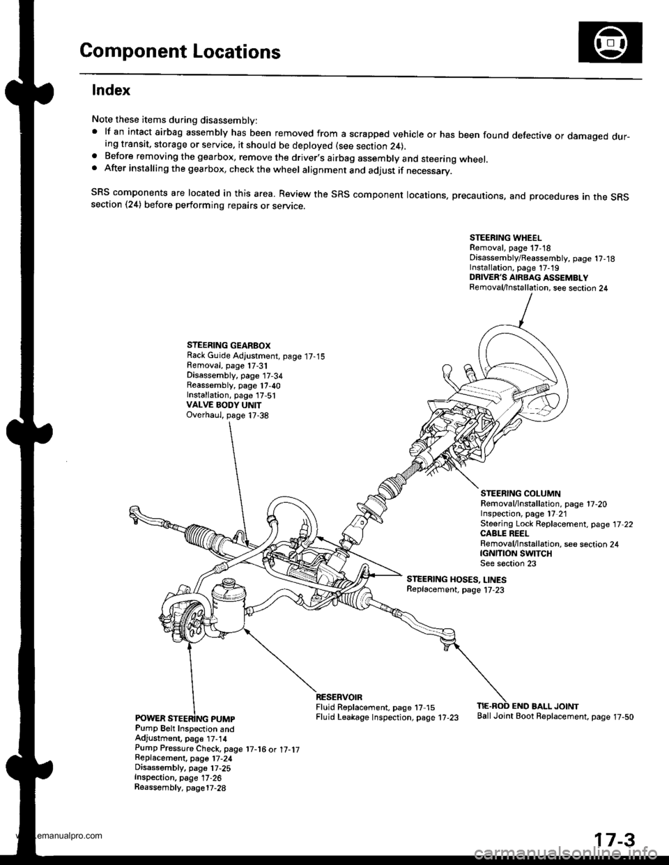
Component Locations
lndex
Note these items during disassembly:' lf an intact airbag assembly has been removed from a scrapped vehicle or has been found defective or damaged dur-ing transit, storage or service. it should be deployed (see section 24),a Before removing the gearbox, remove the driver.s airbag assembly and steering wheel.. After installing the gearbox, check the wheel alignment and adjust if necessary.
SRS components are located in this area. Review the SRS component locations, precautions, and procedures an the SRssection (24) before performing repairs or servrce.
STEERING WHEELRemoval, page 17,18Disassembly/Reassembly, page 1?,18Installation, page 17-19DRIVER'S AIRBAG ASSEMBLYRemoval/lnstallation, see section 24
STEERING GEARBOXRack Guide Adjustment, page 17-15Removal, page 17-31Disassembly, page 17-34Reassembly, page 17,40Installation, page 17,51VALVE BODY UNITOverhaul, page 17-38
STEERING COLUMNRemoval/lnstallation. page 17-20Inspection, page l7 21Steering Lock Replacement, page 17 22CABLE REELRemoval/lnstallation, see section 24tcNrnoN swtTcHSee s€ction 23
STEERING HOSES, LINESReplacement. page l7-23
Pump Belt Inspection andAdjustment, pag€ t7-14Pump Pressure Check, page 17-16 ot 17-1jReplacemont, page 17-24Disassembly, pa96 17,25Inspection, page 17-26Reassembly. page17-28
RESERVOIRFluid R6placement. page 17 15Fluid Leakage lnspection, page 17-23
END BALL JOINTBallJoint Boot Replacement, page 17-50
17-3
www.emanualpro.com
Page 852 of 1395
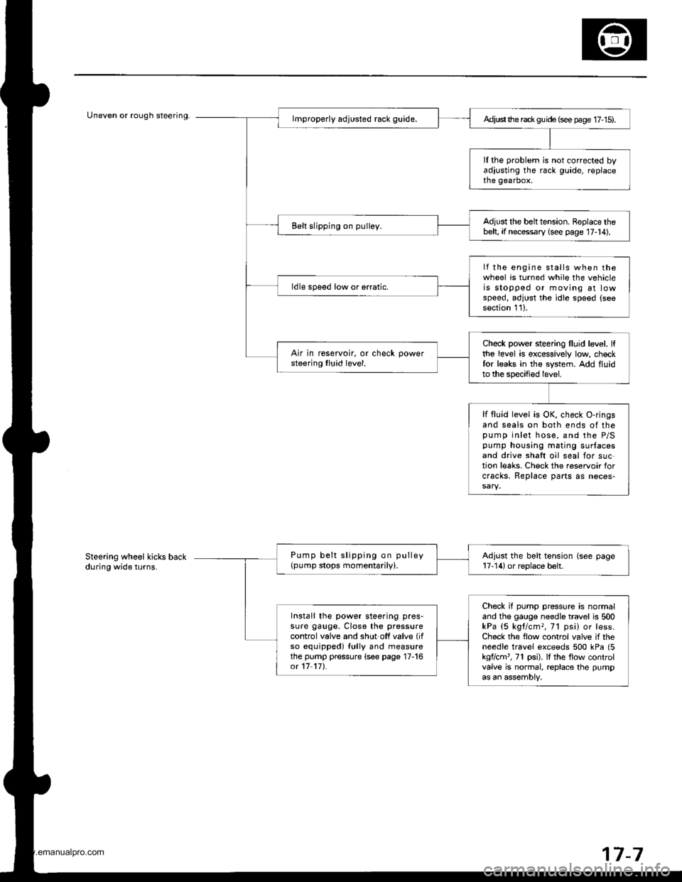
Uneven or rough steering.Ad,ust the rack gu ide (see page 17- 15).
ll the problem is not corrected byadjusting the rack guide, replacethe gearbox.
Adjust the belttension. Replace thebelt, if necessary (see page 17-14).Belt slipping on pulley.
lf the engine stalls when thewheel is turned while the vehicleis stopped or moving at lowspeed, adjust the idle speed (seesection 111.
ldle speed low or erratic.
Check power steering lluid level. lfthe level is excessively low checkfor leaks in the system. Add fluidto the specified level.
Air in reservoir, or check powersteering tluid level.
lf fluid level is OK, check O-ringsand seals on both ends of thepump inlet hose, and the P/Spump housing mating surlacesand drive shaft oil seal for suction leaks. Check the reservoir forcracks, Replace parts as neces-
Pump belt slipping on pulley(pump stops momentarily).Adjust the belt tension (see page17-14) or replace belt.
Check if pump pressure is normaland the gauge needle travel is 500kPa (5 kgl/cm,, 71 psi) or less.Check the flow control valve if theneedle travel exceeds 500 kPa (5kgflcm'�, 71 psi). lI the flow controlvalve is normal, replace the pumpas an assembly,
Install the power steering pres-sure gauge, Close the pressurecontrol valve and shut off valve (if
so equipped) fully and measurethe pump pressure (see page 17-16ot 17 17).
Steering wheel kicks backduring wide turns.
7-7
www.emanualpro.com
Page 853 of 1395
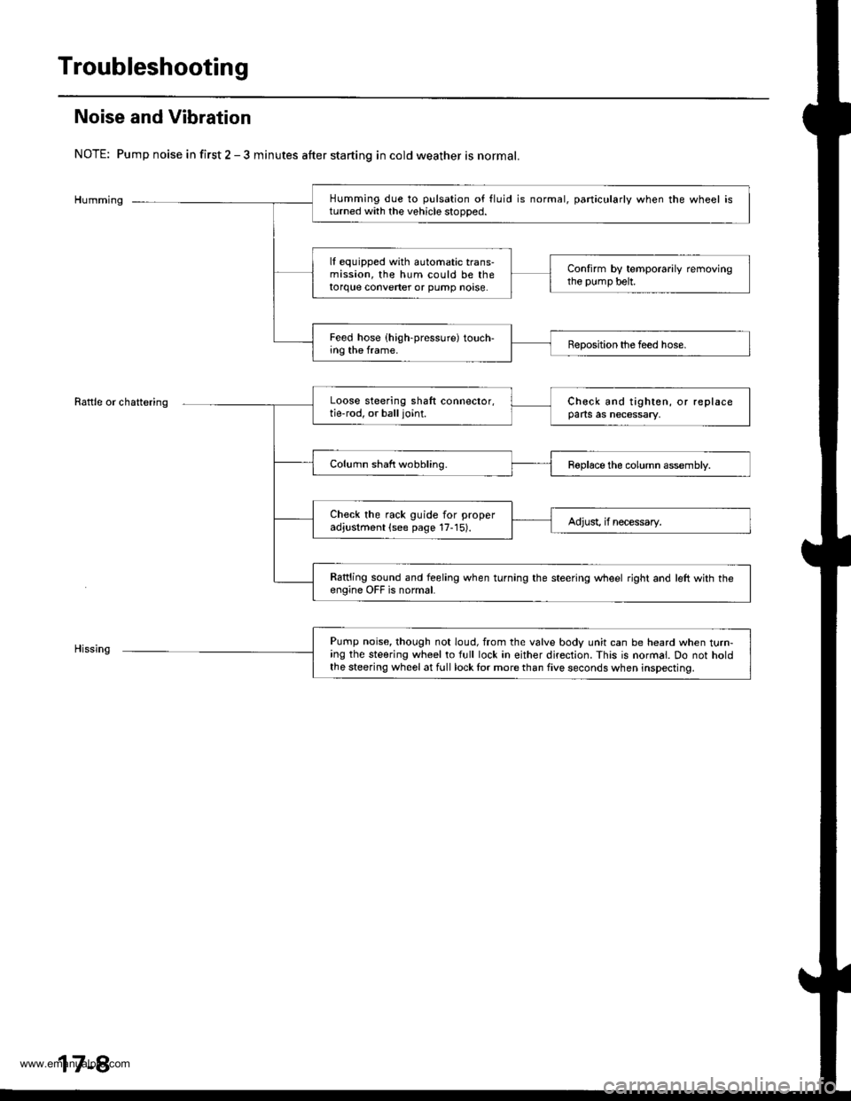
Troubleshooting
Noise and Vibration
NOTE: Pump noise in first 2 - 3 minutes after starting in cold weather is normal.
Humming
Rattle or chattering
Humming due to pulsation of fluid is normal, particularly when the wheel isturned with the vehicle stooDed.
lf equipped with automatic trans-mission, the hum could be thetorque converter or pump noase.
Confirm by temporarily removingthe pump belt.
Feed hose (high-pressure) touch-ing the frame.Beposition the feed hose.
Loose steering shaft connector,tie-rod, or balljoint.Check and tighten, or replaceparts as necessary,
Column shaft wobbling.Roplace the column assembly.
Check the rack guide for properadjustment (see page 17-15).Adjust, if necessary.
Rattling sound and feeling when turning the steering wheel right and left with th€engine OFF is normal.
Pump noise, though not loud, from the valve body unit can be heard when turn-ing the steering wheel to full lock in either direction. This is normal. Do not holdthe steering wheel at full lock lor more than five seconds when inspecting.
17-8
www.emanualpro.com
Page 872 of 1395
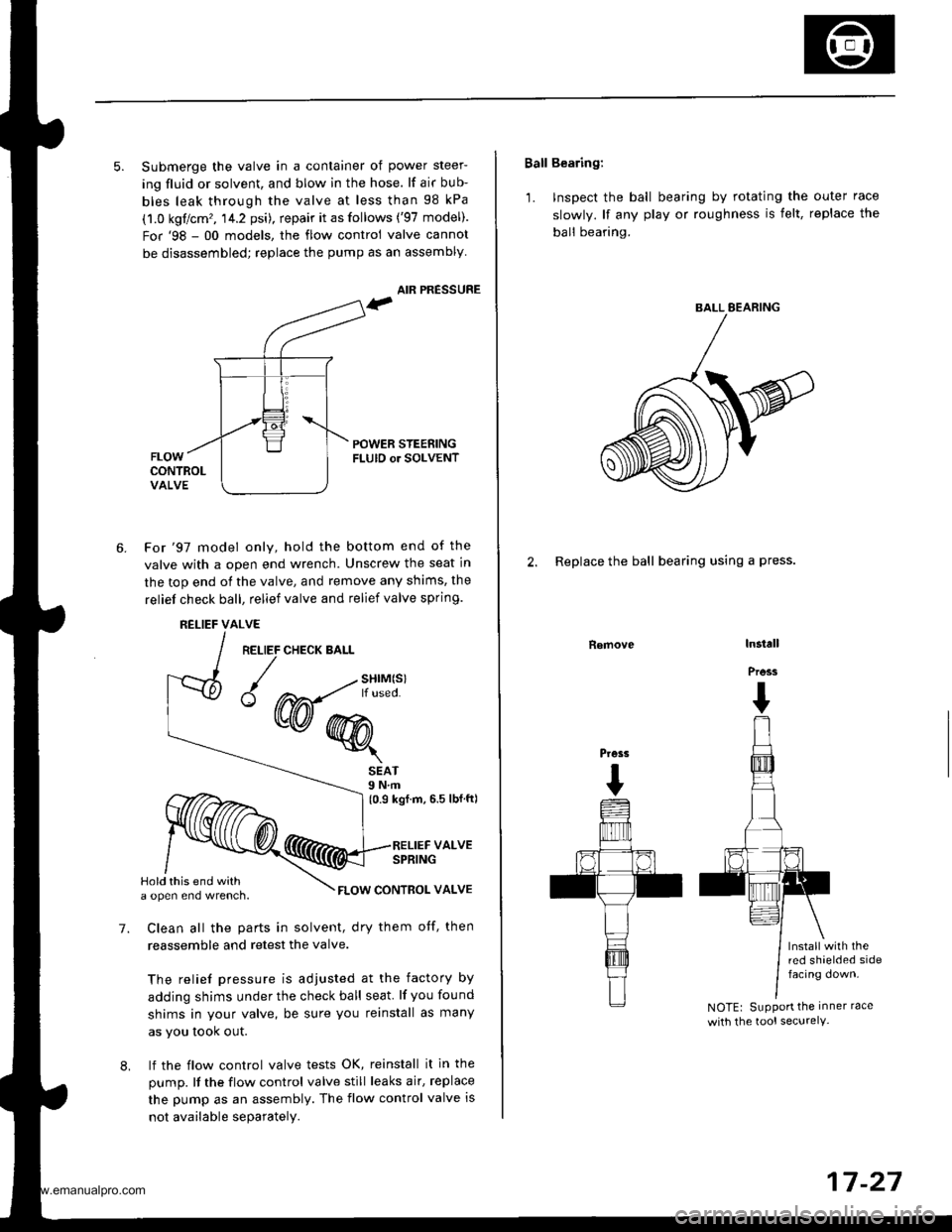
5. Submerge the valve in a container of power steer-
ing fluid or solvent, and blow in the hose. lf air bub-
bles leak through the valve at less than 98 kPa
(1.0 kgflcm'�, 14.2 psi), repair it as follows ('97 model).
For'98 - 00 models, the flow control valve cannot
be disassembled; replace the pump as an assembly
AIR PRESSURE
POWER STEENINGFLUID or SOLVENT
6.For'97 model only, hold the bottom end of the
valve with a open end wrench. Unscrew the seat in
the top end of the valve, and remove any shims, the
reliel check ball, relief valve and relief valve spring.
RELIEFALVE
RELIEF CHECK BALL
{w@r
7.
SEAT9 N.m(0.9 kgf.m, 6.5 lbfft)
RELIEF VALVESPRING
FLOW CONTBOL VALVE
Clean all the parts in solvent, dry them otf, then
reassemble and retest the valve.
The relief pressure is adjusted at the factory by
adding shims under the check ball seat lf you found
shims in your valve, be sure you reinstall as many
as you took out.
lf the flow control valve tests OK, reinstall it in the
pump. It the flow control valve still leaks air, replace
the pump as an assembly. The flow control valve is
not available separately.
8,
Hold this end witha open eno wrencn.
Ball Bearing:
'1. Inspect the ball bearing by rotating the outer race
slowly. lf any play or roughness is felt, replace the
ball bearing.
2. Replace the ball bearing using a press.
Removelnstall
Press
I
Press
I
lnstall with thered shaelded sidefacing down.
NOTEr SuPPort the inner race
with the tool securelY-
BALL EEARING
17-27
www.emanualpro.com
Page 876 of 1395
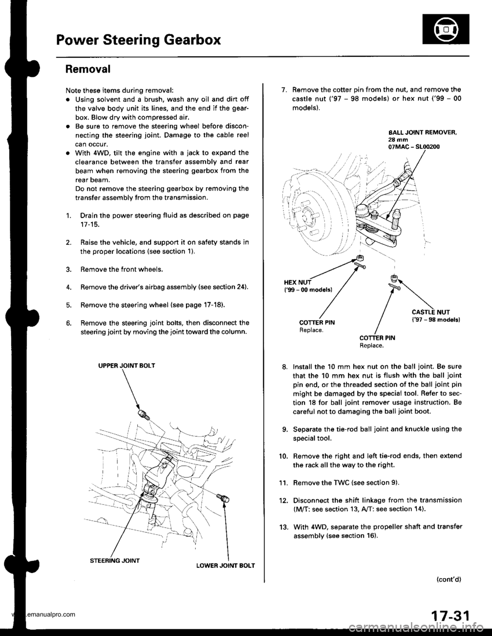
Power Steering Gearbox
Removal
Note these items during removal:
. Using solvent and a brush, wash any oil and dirt off
the valve body unit its lines, and the end if the gear-
box. Blow dry with compressed air.
. Be sure to remove the steering wheel before discon-
necting the steering joint. Damage to the cable reel
can occur.
. With 4WD. tilt the engine with a jack to expand the
clearance between the transfer assembly and rear
beam when removing the steering gearbox from the
rear oeam.
Do not remove the steering gearbox by removing the
transfer assembly from the transmission.
1. Drain the power steering fluid as described on page'17-15.
Raise the vehicle, and suppon it on safety stands in
the proper locations (see section 1).
Remove the front wheels,
Remove the drive/s airbag assembly {see section 24).
Remove the steering wheel {see page 17-18).
Remove the steering joint bolts, then disconnect the
steering joint by moving the joint toward the column.
UPPER JOINT BOLT
LOWER JOINT BOLT
13.
7. Remove the cotter pin from the nut, and remove the
castle nut {'97 - 98 models) or hex nut ('99 - 00
models).
COTTER PINReplace.
Install the 10 mm hex nut on the ball joint. Be sure
that the 10 mm hex nut is flush with the ball joint
pin end, or the threaded section of the ball joint pin
might be damaged by the special tool. Refer to sec-
tion 18 for ball joint remover usage instruction, Be
careful not to damaging the ball joint boot.
Separate the tie-rod ball joint and knuckle using the
special tool.
Remove the right and left tie-rod ends, then extend
the rack all the way to the right.
Remove the TWC (see section 9).
Disconnect the shift linkage from the transmission
(M/T: see section 13, A/T: see section 14).
With 4WD. separate the propeller shaft and transfer
assembly (see section 161.
10.
11.
(cont'd)
17-31
www.emanualpro.com
Page 885 of 1395
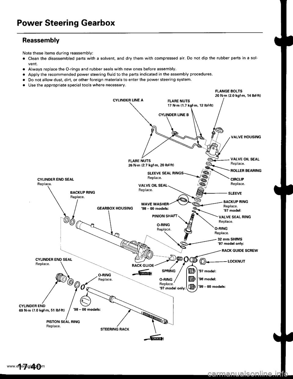
Power Steering Gearbox
Reassembly
Note these items during reassembly
. Clean the disassembled parts with a solvent, and dry them with compressed air. Do not dip the rubber parts in a sol-
vent.
. Always replace the O-rings and rubber seals with new ones before assembly.
. Apply the recommended power steering fluid to the parts indicated in the assembly procedures.
. Do not allow dust. dirt, or other toreign materials to enter the power steering system.
. Use the appropriate specialtools where necessary.
FLANGE BOLTS20 N.m (2.0 kgl.m, 14lbtftl
CYLINDER LINE AFLARE NUTS17 N.m 11.712 rbl.ftl
VALVE HOUSING
CYLINDER END SEALReplace.
VALVE OIL SEALBeplace.
ROLLER BEARING
CIRCLIPReplace.
BA.KUP RING
\/^"
WAVE WASHERBACKUP RINGReplace.97 model:HOUSING
VALVE SEAL RINGReplace.
O.RINGReplace.
32 mm SHIMS'97 mod6l only:
RACK GUIDE SCREW
O-RINGReplace.
@---r-ocxr'rur
'97 model:
'98 model:
'99 - 0O mod6ls:'9? model only:
CYLINDER END69 N.m (7.0 kgf.m, 51 lbf.ft)'98 - (x) models:
PISTON SEAL RINGReplace.
17-40
STEERING RACK
www.emanualpro.com
Page 892 of 1395
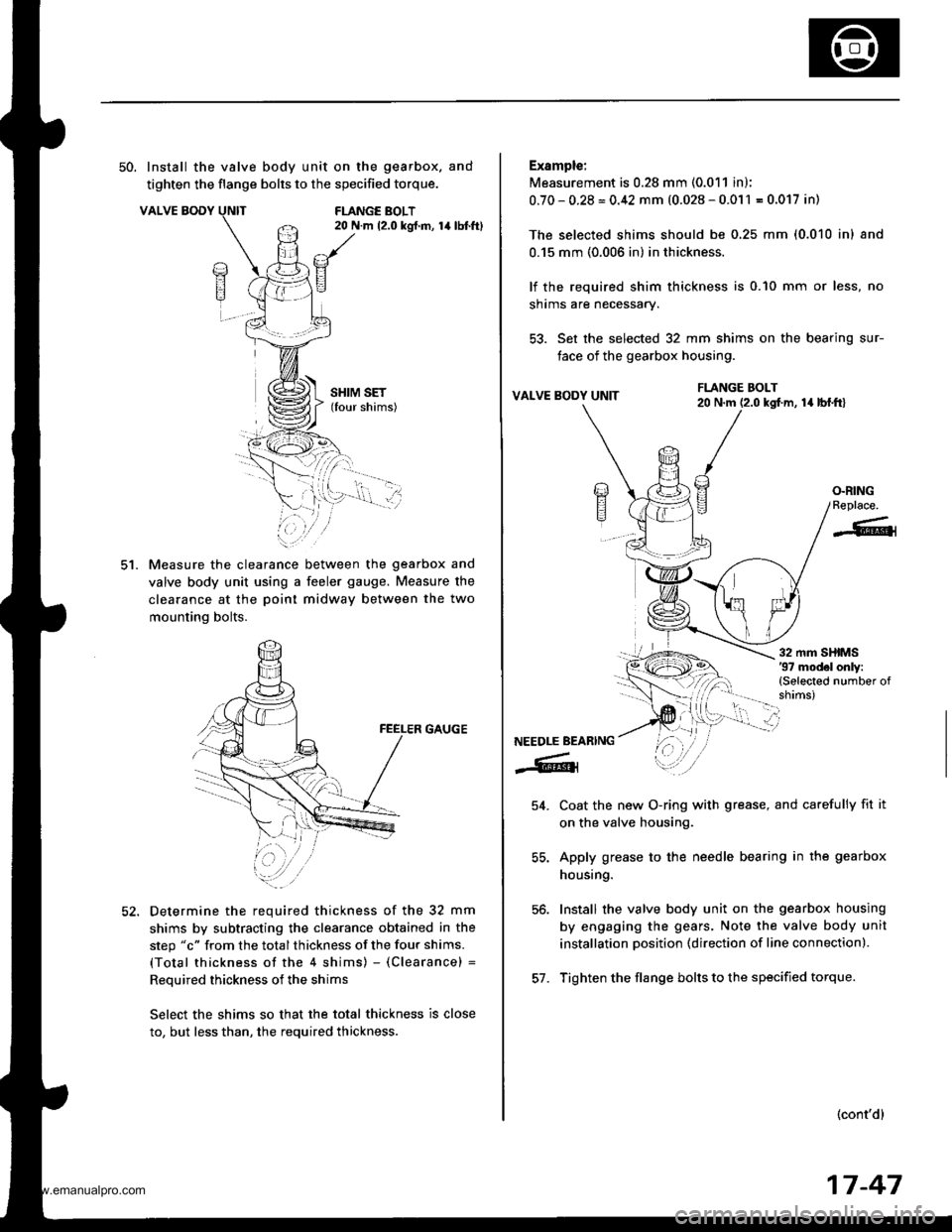
50. Install the valve body unit on the gearbox. and
tighten the flange bolts to the specified torque.
VALVE BODYFLANGE BOLT20 N.m 12.0 kgt.m, 14lbtft)
ct.
SHIM SET(four shims)
Measure the clearance between the gearbox and
valve body unit using a feeler gauge. Measure the
clearance at the poinl midway between the two
mounting bolts.
GAUGE
Determine the required thickness of the 32 mm
shims by subtracting the clearance obtained in the
step "c" from the total thickness of the four shims.
(Total thickness of the 4 shims) - (Clearance) =
Reouired thickness of the shims
Select the shims so that the total thickness is close
to, but less than, the required thickness.
Example:
Measurement is 0.28 mm (0.011 in);
0.70-0.28=0.42 mm (0.028-0.011 = 0.017 in)
The selected shims should be 0,25 mm (0.010 inl and
0.15 mm (0.006 in) in thickness.
lf the required shim thickness is 0.10 mm or less, no
shrms are necessary.
53. Set the selected 32 mm shims on the bearing sur-
face of the gearbox housing.
VALVE BODY UNITla lbl.frl
Coat the new O-ring with grease, and carefully fit it
on the valve housing.
Apply grease to the needle bearing in the gearbox
housing.
Install the valve body unit on the gearbox housing
by engaging the gears. Note the valve body unit
installation position (direction of line connection).
Tighten the flange bolts to the specified torque.
(cont'd)
FLANGE BOLT20 N.m (2.0 kgf.m,
/a)E?
E
O.RINGReplace.
-6{
NEEDLE BEARING
-6lr
54.
56.
57.
17-47
www.emanualpro.com
Page 937 of 1395

Master Cylinder/Brake Booster
Removal/lnstallation
1, Disconnect the brake fluid level switch connectors.
2. Remove the reservoir cap from the master cylinder.
3. Remove the brake fluid from the master cvlinder
reservoir with a syringe.
4. Disconnect the brake lines from the master cylinder.
To prevent spills, cover the line joints with rags or
shop towels.
5. Remove the master cylinder mounting nuts and
wasners.
6. Remove the master cylinder from the brake booster.
CAUTION: Be careful not to bend or damage the
brake lines when removing the master cylinder.
Do not spill brake fluid on the vehicle; it may dam.
age the paint; it brake fluid does cont.ct the paint,
wash it oft immediately with water.
7. Disconnect the vacuum hose from the brake booster.
8. Remove the cotter pin and clevis pin from the clevis.
Do not disconnect the clevis by removing it from
the operating rod of the brake booster. lf the clevis
is loosened, adjust the pushrod length before
installing the brake booster (see page 19-15).
To Front Caliper (Without ABS)
\\
15 N.m {1.5 kgtm, vAcuuM HosE
r r rbf.ft) |
/ | BRAKE FLUTD LEvEL
/l /
swrrcHcoNNEcroRs
/ I I I COTTER PIN
I I / neotace
l,/-- ro Rear wheet cylinders / | I
h ./-''' /. I I IYli //*s (.S
I /r:
9. Remove the four booster mounting nuts.'10. Pull the brake booster forward until the clevis is
clear of the bulkhead.
11. Remove the brake booster from the enqine com-
panment.
12. Install the brake booster and master cylinder in the
reverse order of removal, and note these items:
. When connecting the brake lines, make sure that
there is no interference between the brake lines
and other parts.
. Be careful not to bend or damage the brake lines
when installing the master cylinder.
. lf replacing the master cylinder or brake booster,
check and adjust the pushrod clearance before
installing the master cylinder (see page 19-14).
Fill the master cylinder reservoir, and bleed the
brake system (see page 19-7).
After installation, check the brake pedal height and
brake pedal free play (see page 19-5), and adjust if
necessary.
13 N.m 11.3 kg{.m,I rbf.ft)
13.
14.
To Master Cylinder(Without ABS)To Modulator Unit(with ABs)@-\
\
^ To Front Caliper
9i\.
-#qCLEVIS PIN
):-,/
PROPORTIONING CONTROL VALVE
MASTER CYLINDER
15 N.m (1.5 kgf.m, 11 lbl.ftl
BRAXE BOOSTER
www.emanualpro.com
Page 939 of 1395
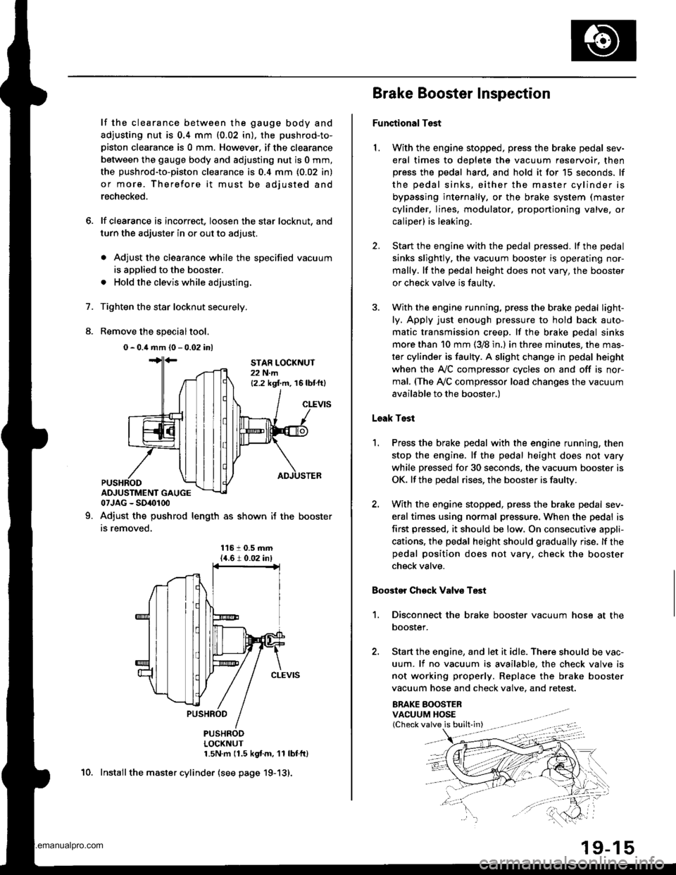
6.
7.
8.
lf the clearance between the gauge body and
adjusting nut is 0.4 mm (0.02 in), the pushrod-to-
piston clearance is 0 mm. However. if the clearance
between the gauge body and adjusting nut is 0 mm,
the pushrod-to-piston clearance is 0.4 mm (0.02 in)
or more. Therefore it must be adjusted and
recheck€d.
lf clearance is incorrect, loosen the star locknut, and
turn the adjuster in or out to adjust.
. Adjust the clearance while the specified vacuum
is applied to the booster.
. Hold the clevis while adjusting.
Tighten the star locknut securely.
Remove the special tool.
0 - 0.4 mm (0 - 0.02 inl
Adjust the pushrod length as shown if the
is removed,
booster
11610.5 mm{4.6 t 0.02 inl
PUSHRODLOCKNUT1.5N.m 11.5 kgf.m. '11 lbtfl)
Install the master cylinder (see page 19-13).
9.
STAR LOCKNUT22 N.m12.2 kgt m. 16 lbtftl
10.
(Check valve is built-in)
Brake Booster Inspection
FunctionalTest
1. With the engine stopped, press the brake pedal sev-
eral times to deplete the vacuum reservoir. thenpress the pedal hard, and hold it for 15 seconds. lf
the pedal sinks, either the master cylinder is
bypassing internally, or the brake system (master
cylinder, lines, modulator, proportioning valve. or
caliper) is leaking.
2. Start the engine with the pedal pressed. lf the pedal
sinks slightly. the vacuum booster is operating nor-
mally. lf the pedal height does not vary, the booster
or check valve is faultv.
3. With the engine running, press the brake pedal light-
ly. Apply just enough pressure to hold back auto-
matic transmission creep. lf the brake pedal sinks
more than 10 mm (3/8 in.) in three minutes, the mas-
ter cylinder is faulty. A slight change in pedal height
when the Ay'C compressor cycles on and off is nor-
mal. (The Ay'C compressor load changes the vacuum
available to the booster.)
Leak Test
1.Press the brake pedal with the engine running, then
stop the engine. lf the pedal height does not vary
while pressed for 30 seconds, the vacuum booster is
OK. lf the pedal rises, the booster is faulty.
With the engine stopped, press the brake pedal sev-
eral times using normal pressure. When the pedal is
first pressed. it should be low, On consecutive appli-
cations, the pedal height should gradually rise. lf thepedal position does not vary. check the booster
check valve.
Boostor Chock Valve Test
1. Disconnect the brake booster vacuum hose at the
booster.
2. Start the engine, and let it idle. There should be vac-
uum. lf no vacuum is available, the check valve is
not working properly. Replace the brake booster
vacuum hose and check valve. and retest.
ERAKE BOOSTERVACUUM HOSE
www.emanualpro.com
Page 952 of 1395
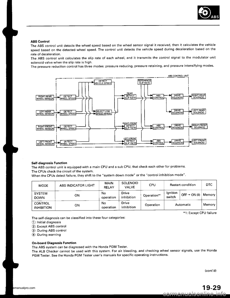
ABS Control
The ABS control unit detects the wheel speed based on the wheel sensor signal it received, then it calculates the vehicle
speed based on the detected wheel speed. The control unit detects the vehicle speed during deceleration based on the
rate of deceleration.
The ABS control unit calculates the slip rate of each wheel, and it transmits the control signal to the modulator unit
solenoid valve when the slip rate is high
The pressure reduction control has three modes: pressure reducing, pressure retaining, and pressure intensi{ying modes.
Self-diagnosis Function
The ABS control unit is equipped with a main cPU and a sub cPU, that check each other for problems.
The CPUs check the circuit of the system.
When the CPUS detect failure, they shift to the "system down mode" or the "control inhibition mode".
The self-diagnosis can be classitied into these four categories:
O: Initial diagnosis
O: Except ABS control
O; During ABS control
@: During warning
On-board Diagnosis Function
The ABS system can be diagnosed with the Honda PGM Tester.
The ALB Checker cannot be used with this system. For air bleeding. and checking wheel sensor signals, use the Honda
PGIM Tester. See the Honda PGM Tester user's manuals for specific operating instructions.
(cont'd)
19-29
ABS CONTROL I-INIT
MODEABSINDICATOR LIGHTMAIN
RE LAY
SOLENOID
VALVERestan conditionDTC
SYSTEM
DOWNONNo
operatron
Drive
inhibitionOperation*rlgnition
switchOFF - oN (ll)Memory
CONTROL
INHIBITIONONNo
operaton
Drive
inhibitionOperationAutomaticlVemory
*1: Except CPU failure
www.emanualpro.com