HONDA CR-V 2000 RD1-RD3 / 1.G Workshop Manual
CR-V 2000 RD1-RD3 / 1.G
HONDA
HONDA
https://www.carmanualsonline.info/img/13/5778/w960_5778-0.png
HONDA CR-V 2000 RD1-RD3 / 1.G Workshop Manual
Trending: Oil pump ring, Locking, temp gauge stuck, width, quarter glass replacement, Quarter glass, Misfire
Page 1081 of 1395
Wiper/Washer
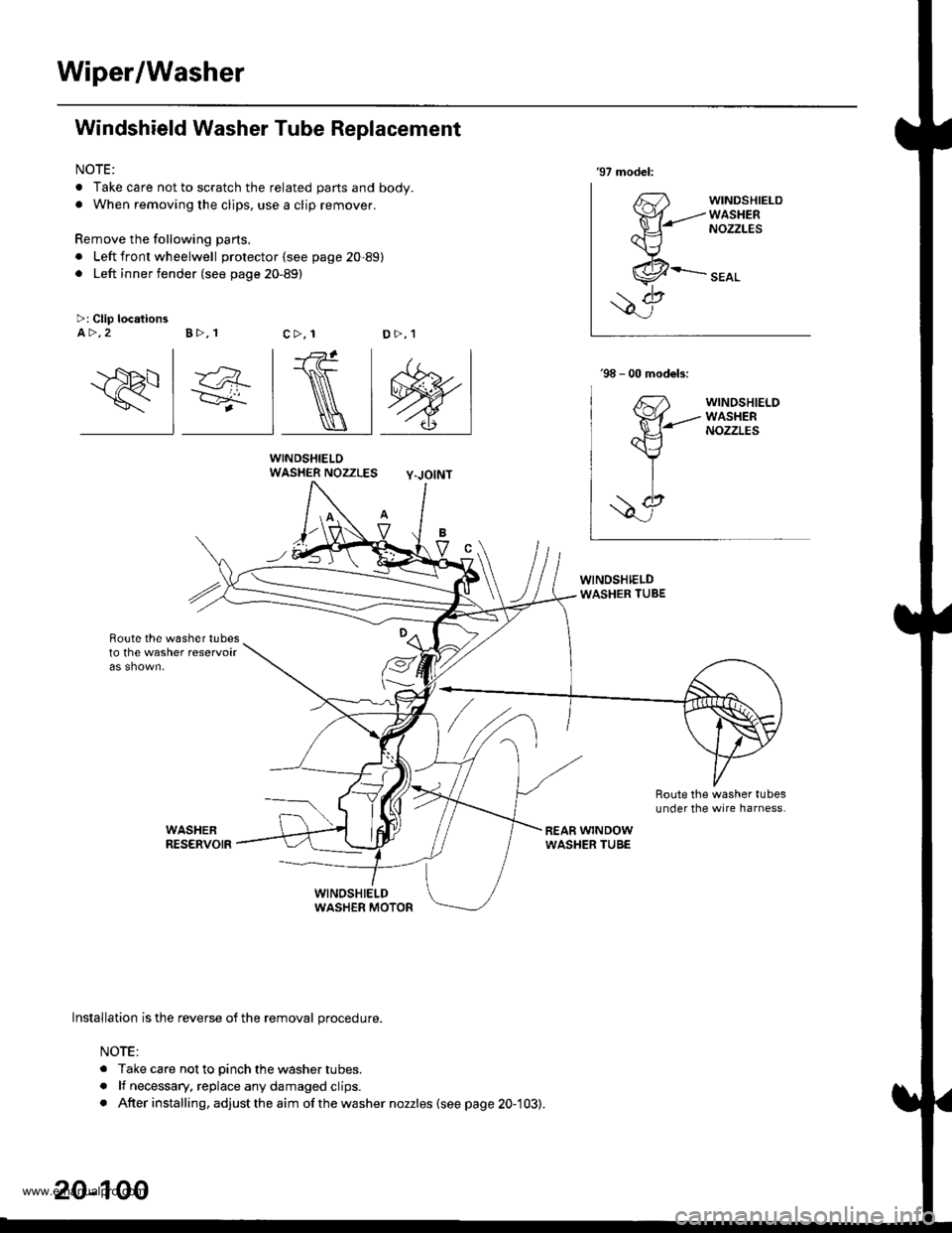
Windshield Washer Tube Replacement
NOTE:
. Take care not to scratch the related parts and body.. When removing the clips, use a clip remover.
Remove the following parts.
. Left front wheelwell protector (see page 20-89). Left inner fender (see page 20-89)
WINDSHIELOWASHER NOZZLES Y-JOINT
Boute the w6sher tubesto the washer reservoir
'97 model:
63'fr{-------
ax---\J
,.&--
\7>: Clip locationsA >,2 B >,1c>, 1D>,1
\
lnstallation is the reverse of the removal procedure.
NOTE:
. Take care not to pinch the washer tubes.
. lf necessary, replace any damaged clips.. After installing, adjust the aim ofthe washer nozzles (see page 20-103).
20-100
www.emanualpro.com
Page 1082 of 1395
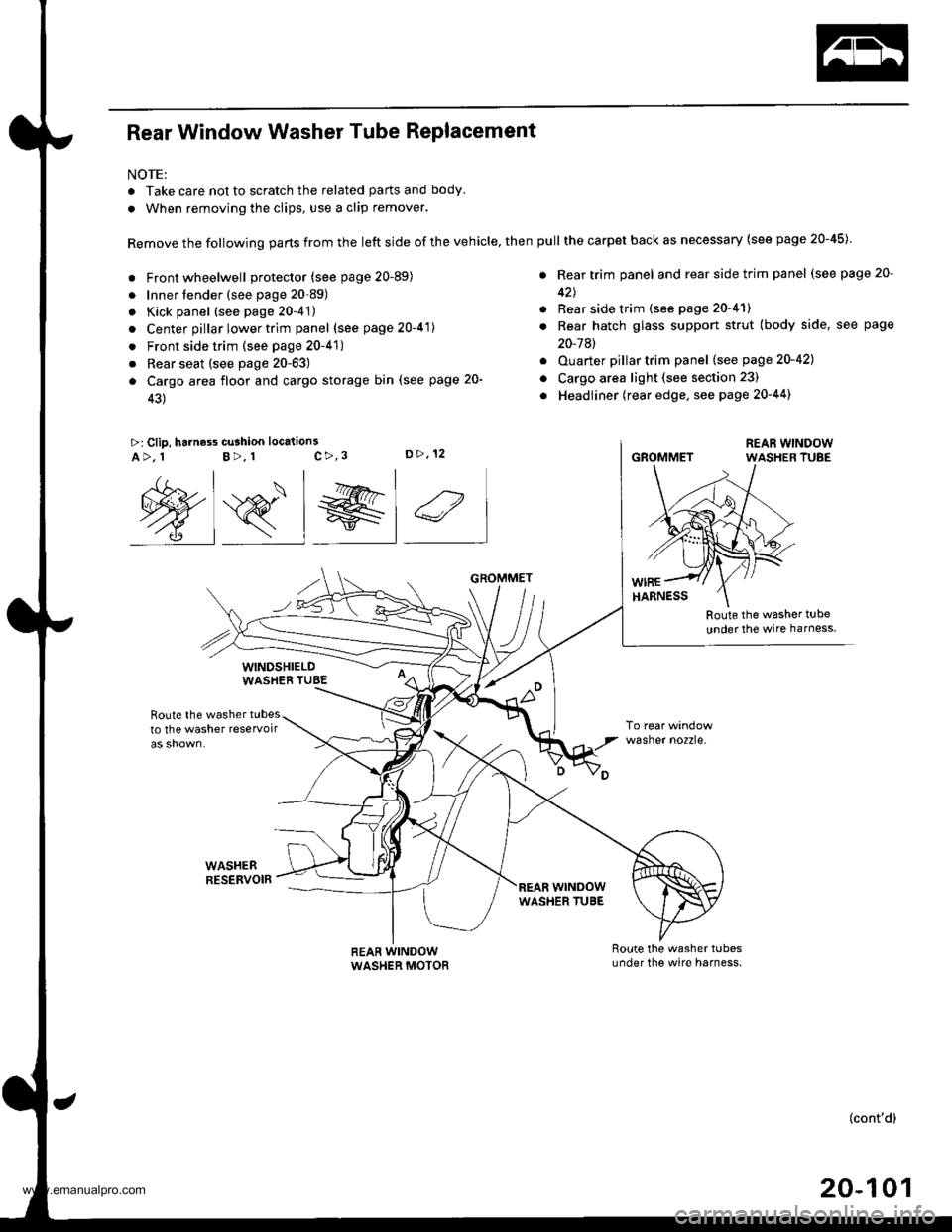
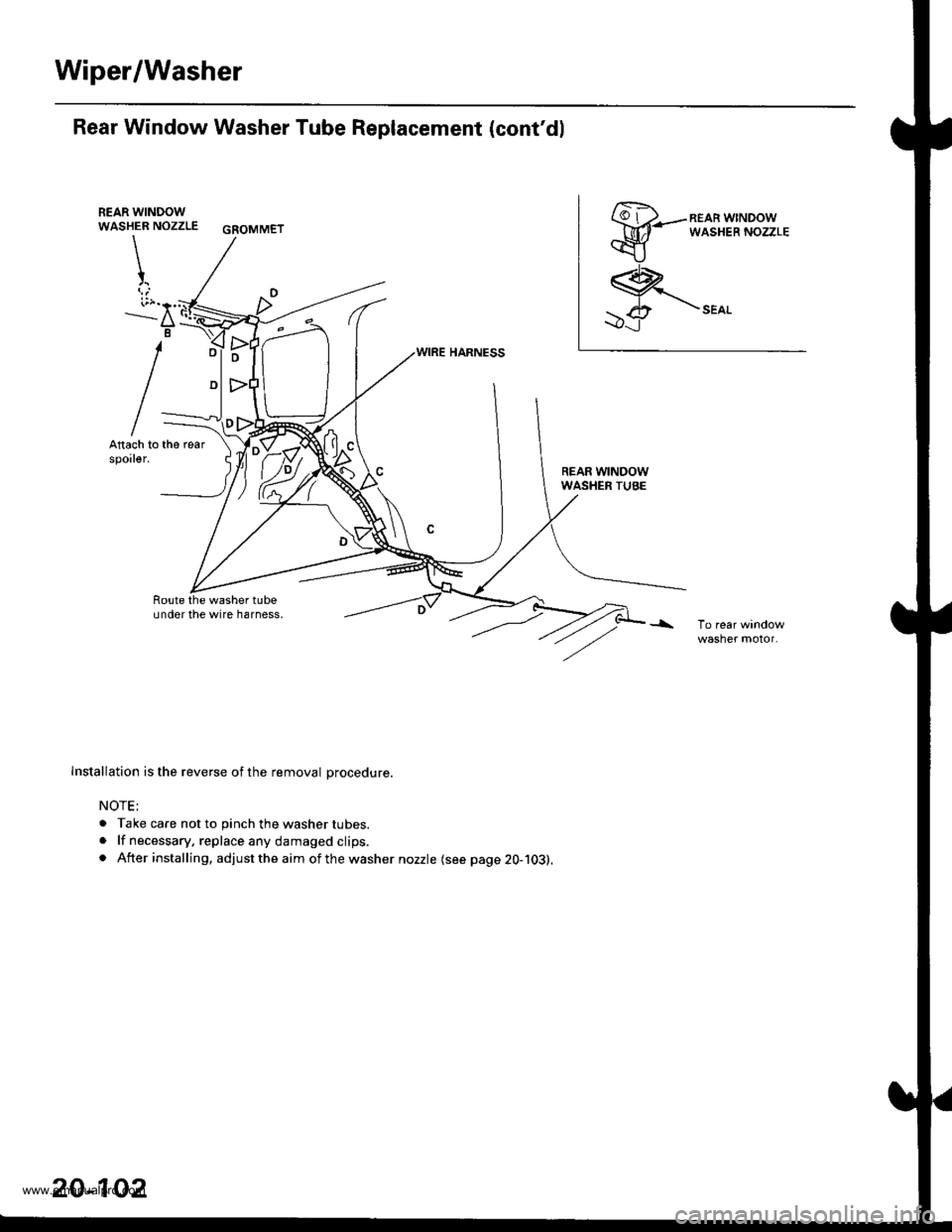
Rear Window Washer Tube Replacement
NOTE:
. Take care not to scratch the related parts and body.
. When removing the clips, use a clip remover.
Remove the following parts from the left side of the vehicle, then
. Front wheelwell protector (see page 20-89)
. Innertender (see page 20-89)
. Kick panel (see page 20-4't)
. Center pillar lower trim panel (see page 20-41)
. Front side trim (see page 20-41)
. Rear seat (see page 20-63)
a Cargo area floor and cargo storage bin (see page 20-
43)
>: Clip, harness cu3hion location3c>,3D>,12A>, 1B>, 1
Route the washer t!be
under the wire harness
Route the washer tubesto the washer reservoir
WASHEBRESERVOIR
wasner no2zre.
@s_l el 4
WINDSHIELDWASHEB TUBE
REAR WINDOWWASHER MOTOR
GROMMET
wrNoowWASHER TUBE
pull the carpet back as necessary (see page 20-45)
. Rear trim panel and rear side trim panel (see page 20-
42J
. Rear side trim (see page 20-41)
. Rear hatch glass support strut (body side, see page
20-7Al
. Ouarter pillartrim panel (see page 20-421
o Cargo area light (see section 23)
. Headliner (rear edge, see page 20-44)
GROMMET
(cont'd)
20-101
www.emanualpro.com
Page 1083 of 1395
Wiper/Washer
Rear Window Washer Tube Replacement (cont'dl
REAR WINDOWWASHER NOZZLE GSOMMET
\
t
i;r."'..--a
B
REAR WINDOWWASHER TUBE
Route the washer tubeundor the wire harness,
Installation is the reverse of the removal Drocedure.
NOTE;
. Take care not to pinch the washer tubes.. lf necessary, replace any damaged clips.. After installing, adjust the aim of the washer nozzle (see page 20-103).
20-102
www.emanualpro.com
Page 1084 of 1395
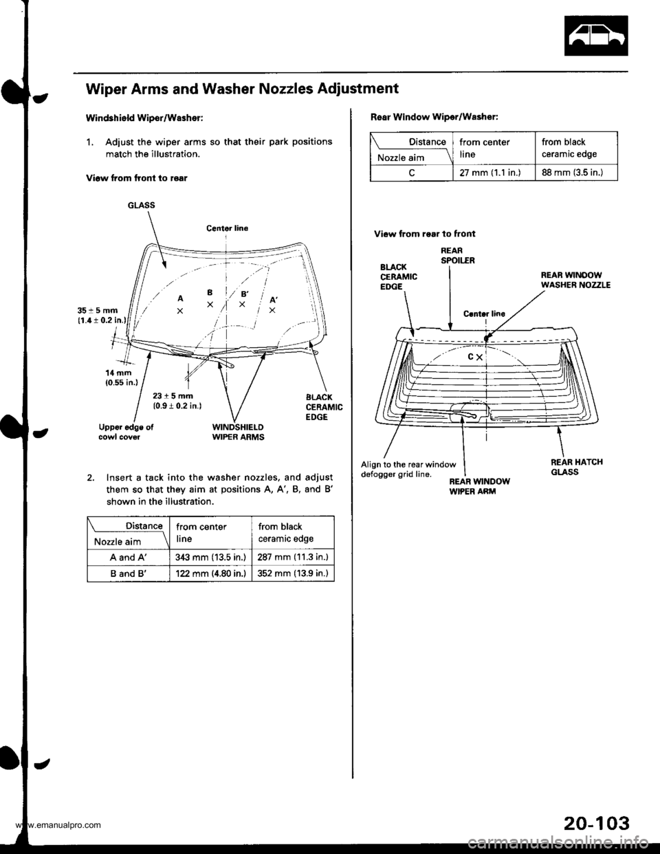
Wiper Arms and Washer Nozzles Adiustmenl
Wind3hield Wipor/Washer:
1, Adiust the wiper arms so that their park positions
match the illustration.
Viow from flont io roar
GLASS
2. Insert a tack into the washer nozzles. and
them so that they aim at positions A, A', B,
shown in the illustration.
adjust
and B'
Distance
^,J;-ll\
from center
line
from black
ceramic edge
A and A'3,$ mm (13.5 in.)287 mm (11.3 in.)
B and B'122 mm (4.80 in.)352 mm (13.9 in.)
Rear Window wipor/Washer:
Vi6w trom roar to lront
REARsPo[.-ER
C.nlar linoL
Align to the rear windowdefogger grid line.
Distance
ru"rrr. "i.
'_\from center
ltne
from black
ceramic edge
27 mm (1.1 in.)88 mm (3.5 in.)
20-103
www.emanualpro.com
Page 1085 of 1395
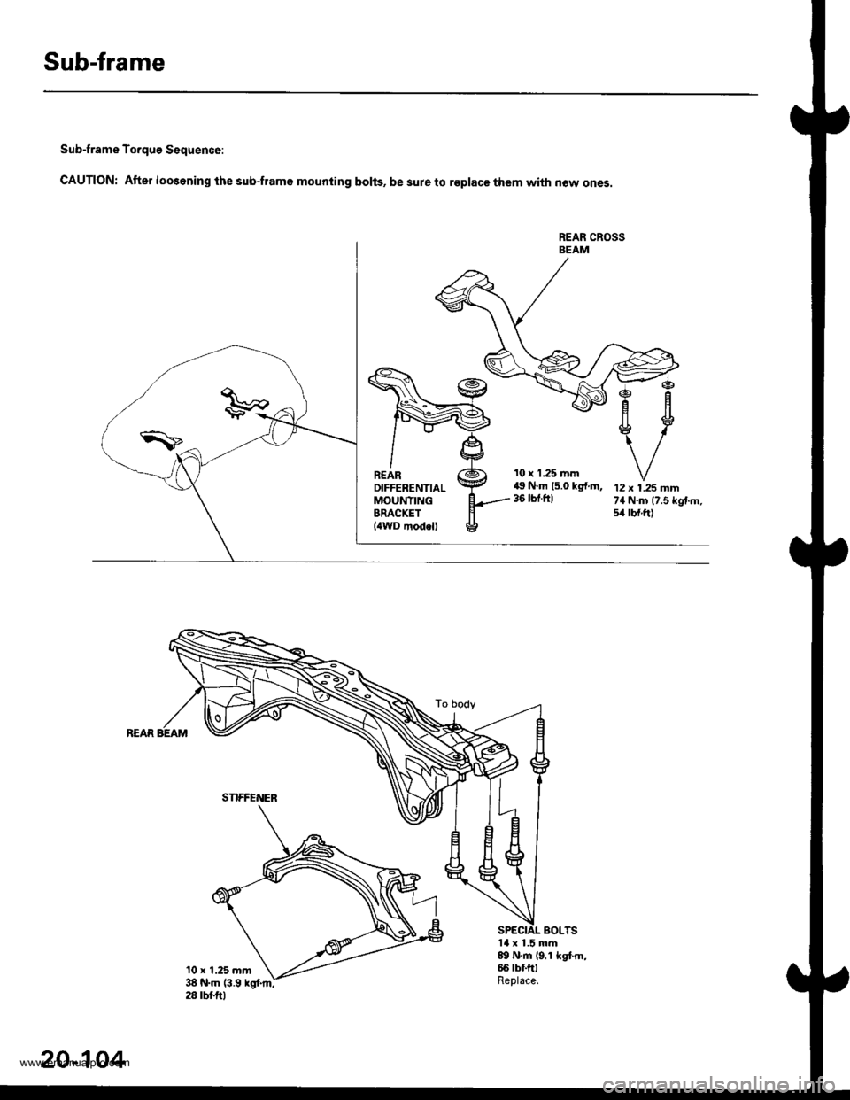
Sub-frame
Sub-frame To.que Sequence:
CAUTION: After loo3ening the sub-frame mounting bolts, be sure to replace them with now ones.
REAN CROSSBEAM
10 r 1.25 mm49 N.m 15.0 kg{.m,36 tbt.ftl12 x 1.25 mm74 N.m (7.5 kgtm.54 tbf.ft)
BOLTS1l x 1.5 mm89 N.m 19,1 kgt m,66 tbt ftlReplace.
SNFFENER
20-104
www.emanualpro.com
Page 1086 of 1395
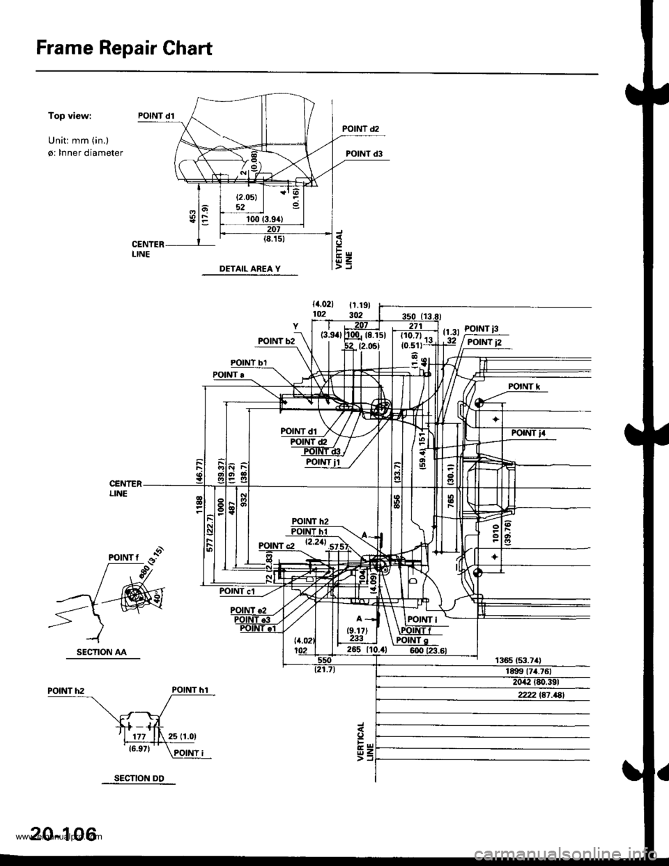
Frame Repair Chart
Top view:
Unit: mm (in.)
0: Inner diameter
{4.021 t1.19}lm 302
tr.rr !9$IPOtt{T
POINT'
POINT hl
20-106
SECTION DD
www.emanualpro.com
Page 1087 of 1395
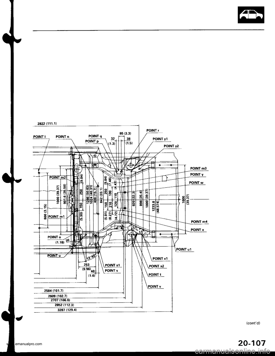
2&2 t111.11
258,1{10r.7}
I POINT n
(cont'd)
20-107
32A7 1129.11
www.emanualpro.com
Page 1088 of 1395
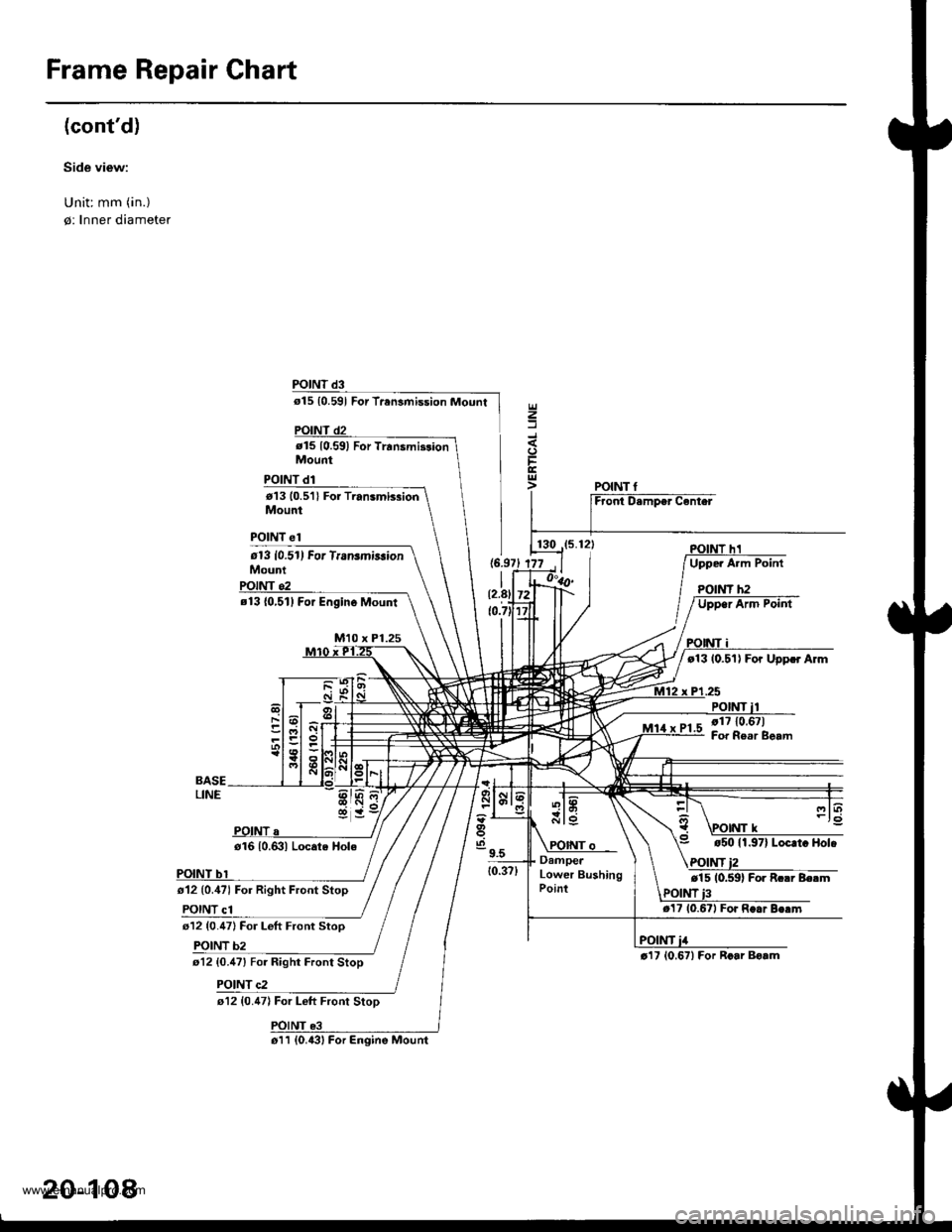
Frame Repair Chart
(cont'd)
Side view:
Unit: mm (in.)
0: Inner diamete.
POINT d3
o15 {0.591 For Trensmission Mount
d15 10.591 For Trrnsmi3donMount
POINT d1
t13 10.5'll For Transmb3ionMount
POINT el
613 10.51) For TransmirsionMouni
z
t13 {0,511 For Engin6 Mount
M10 x Pl.25
t13 10.51) For Uppcr Arm
.25
POINT,1710.67)Fof Re.r Beam
o12 (0.,171 For Right Front Stop
POINT c1
o16 10.631 Locate Hole
612 {0.47} For Left Front Stoo
b2
r12 {0.47) For Left Front StoD
t5011.97| Locrt. Hol.
POINT
t17 10.671 Fo. R..r
r'17 10.671 For Rcar Bo.mt12 {0.47} For Right Front Stop
POINT c2
130POINT h1
DamperLower BushingPoint
o11 (0.{31 For Engine Mount
20-108
www.emanualpro.com
Page 1089 of 1395
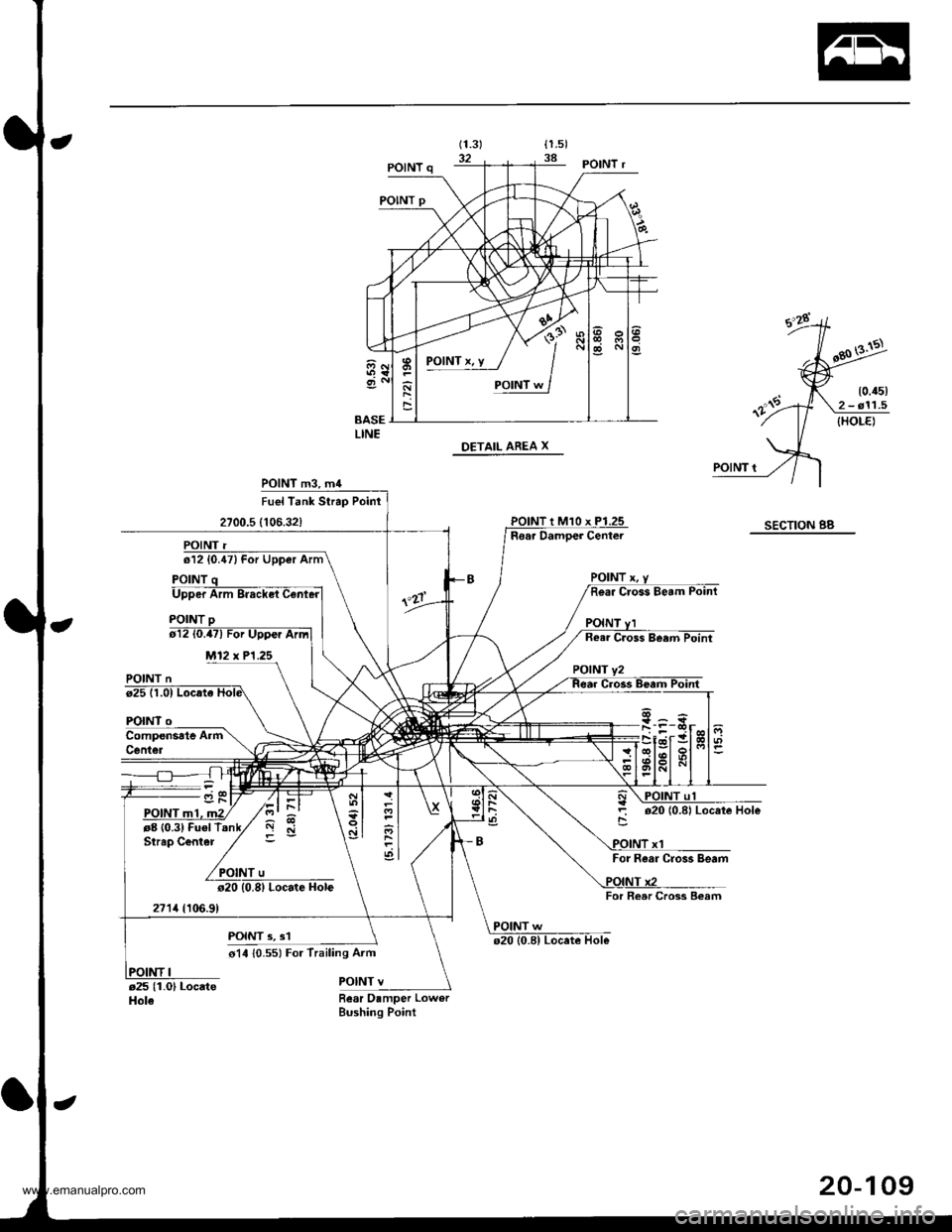
POlNTx.y / I
'sad
POINT m3, m4
Upper Arm
M12 x P1.25
Locate Hole
POINT 3, s1
o14 {0.551 For Trailing Aim
POINT v
Fuel Tank Strap Poinr
2700.5 (106.32)SECTION BBRear Damoer Center
POINT n
FOINT
rg (0.3) Fuel TStrap Center
271,1(10,6.9)
o2010.8| Locate Hole
For Rear Cros3 Beam
For Reer Cross Beam
POINT w
Bear Damper LowerBushing Point
I
\-
ql
ol
.df
20-109
www.emanualpro.com
Page 1090 of 1395
a
Heater and Air Conditioning
Heater ...........21
NOTE: Section 21 ("Heater") is included in section 22.
Air Conditioning ......'..'.. '.'22'1
SUPPLEMENTAL RESTRAINT SYSTEM (SRS}
This model has an SRS which includes a driver's airbag in the steering wheel hub, a passenger's airbag in the dashboard
above the glove box ('97,00 models). and seat belt tensioners in the seat belt retractors ('98 - 00 models). Information
necessary to safely service the SRS is included in this Service Manual. ltems marked with an asterisk (*) on the contents
page include. or are located near, SRS components. Servicing, disassembling or replacing these items will require special
precautions and tools, and should only be done by an authorized Honda dealer.
@. To avoid rendering the SRS inoperative, which could lead to personal iniury or death in the event of 8 severe frontal
collision, all SRS service work must be performed by an authotized Honda dealer.
lmproper service procedures, including incorrect removal and installation of the SRS, could lead to personal iniury
caused by unintentional deployment of the airbags ('97 - 00 models), and seat belt tensioners 138 - 00 models).
Do not bump the SRS unit. Otherwise, the system may fail in case of a collision, or the airbags may deploy when the
ignition switch is ON {lll.
SRS eleqtrical wiring harnesses are identified by yellow color coding. Related components are located in the steering
column, front console, dashboard, dashboard lower panel, and in the dashboard above the glove box. Do not use elec-
tricaltest equipment on thes€ cilcuils.
www.emanualpro.com
Trending: Air Intake, Component wiring, service, key battery, fuel cap release, Overheating, dash lights
