Door HONDA CR-V 2000 RD1-RD3 / 1.G Workshop Manual
[x] Cancel search | Manufacturer: HONDA, Model Year: 2000, Model line: CR-V, Model: HONDA CR-V 2000 RD1-RD3 / 1.GPages: 1395, PDF Size: 35.62 MB
Page 1294 of 1395

Power Windows
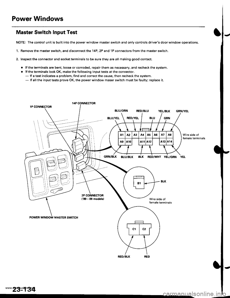
Master Switch Input Test
NOTE: The control unit is built into the power window master switch and only controls driver's door window operations.
1. Remove the master switch, and disconnect the 14P,2? and 1P connectors from the master switch.
2. Inspect the connector and socket terminals to be sure they are all making good contact.
. lf the terminals are bent, loose or corroded, repair them as necessary, and recheck the system,
. lf the terminals look OK, make the following input tests at the connector.- lf a test indicates a problem, find and correct the cause, then recheck the system.- lf all the input tests prove OK, the power window maser switch must be faulty; replace it.
1P CONNECTOR
BLU/ORN RED/BLUYEL/BLK
BLU/YEL RED/YELGRN
GRN/YEL
POWER WINDOW MASTEB SWITCH
GRN/BLK aLu/BLK BLK RED/WHT YEL/GRN YEL
Wire side offemale terminals
RED/BLK
lirP CONNECTOR
23-134
Wire side oIfemale terminals
.-
www.emanualpro.com
Page 1297 of 1395

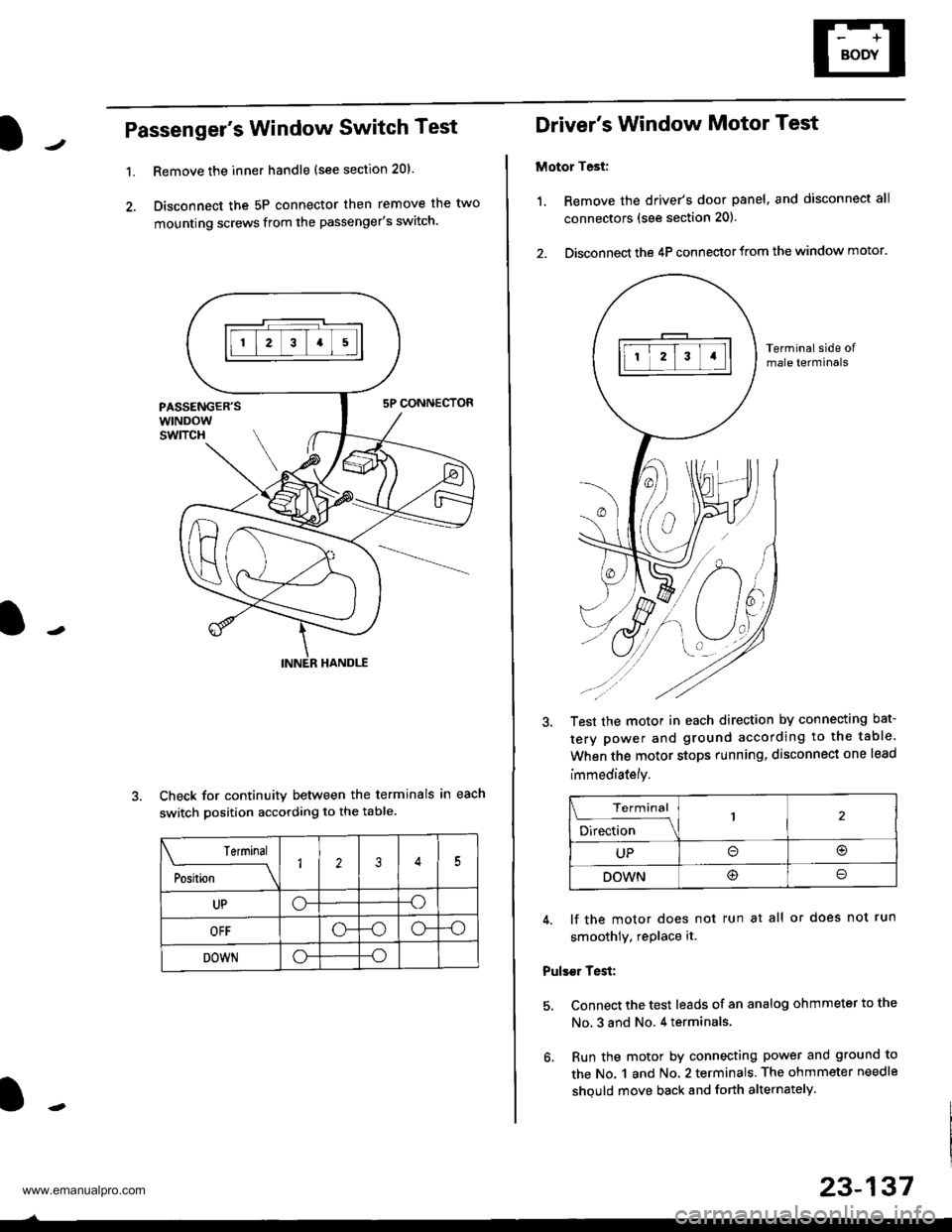
Passenger's Window Switch Test
1.Remove the inner handle (see section 20).
Disconnect the 5P connector then remove the two
mounting screws from the passenger's switch.
Check for continuity between the terminals in each
switch position according to the table
Terminal
;"rL-
__\1235
UPo--o
OFF-oo--o
DOWNo--o
Driver's Window Motor Test
Motor Test:
1. Remove the driver's door panel, and disconnect all
connectors (see section 201.
2. Disconnect the 4P connector from the window motor.
Terminal side ofmale terminals
Test the motor in each direction by connecting bat-
tery power and ground according to the table.
When the motor stops running. disconnect one lead
immediately.
Terminal
;;b"
-\
UPo(!r
DOWN@o
4. lf the motor does not run at all or does not run
smoothly. rePlace it.
Pulser Test:
5. Connect the test leads of an analog ohmmeter to the
No, 3 and No. 4 terminals.
6. Run the motor by connecting power and ground to
the No. 1 and No. 2 terminals. The ohmmeter needle
shquld move back and forth alternately.
23-137
www.emanualpro.com
Page 1298 of 1395

Power Windows
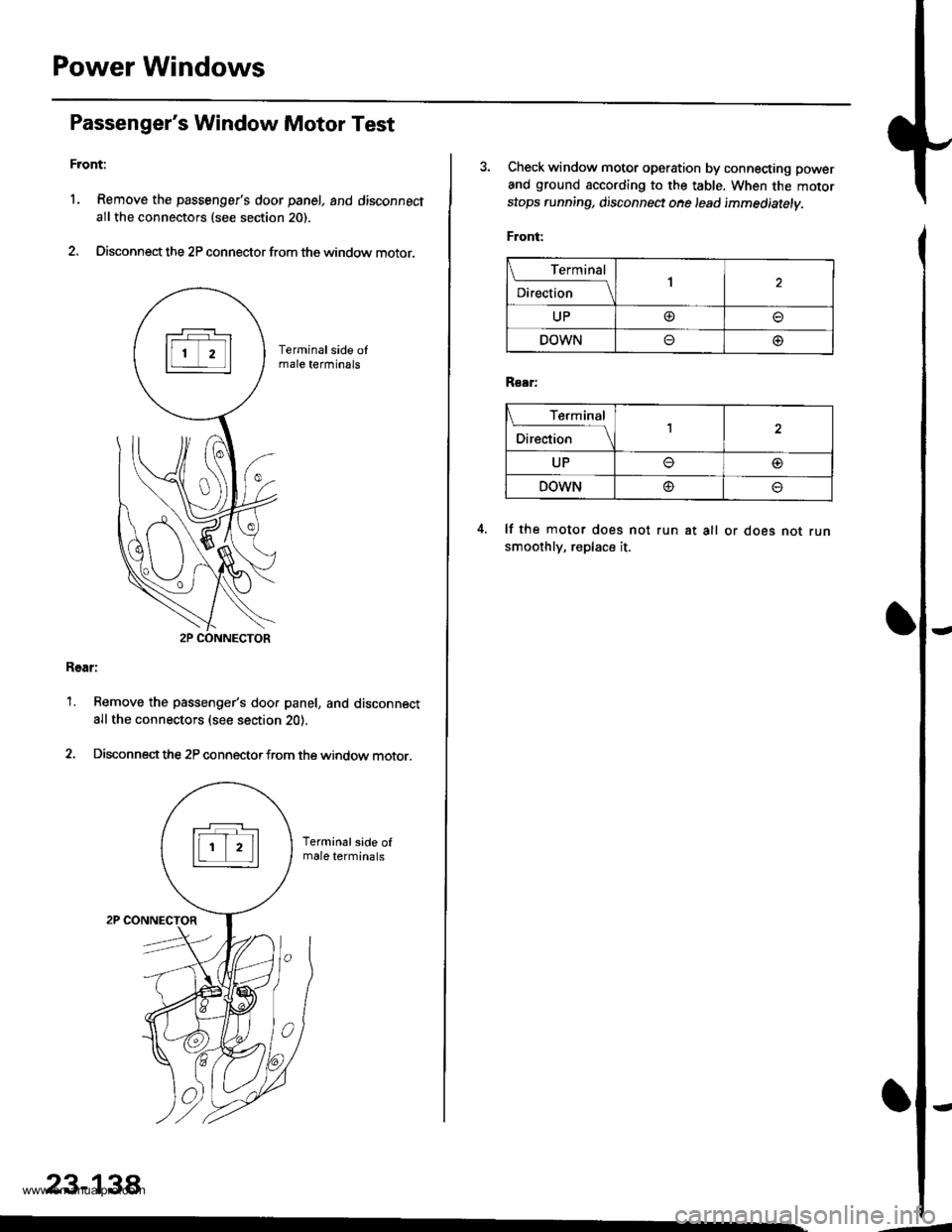
Passenger's Window Motor Test
Front:
l. Remove the passenger's door panel, and disconnect
allthe connectors (see section 20).
2. Disconnect the 2P connector from the window motor.
Rear:
1. Remove the passenger's doo. panel, and disconnect
allthe connectors (see section 20).
2. Disconnectthe 2P connectorfrom the window motor.
23-138
3. Check window motor operation by connecting power
and ground according to the table. When the motor
stops running, disconnect ohe lead immediatelv.
Front:
Terminal
;."b"
.l\
UP@
DOWNo@
R€ar:
I Terminal
;*r*
-l\
UPo@
DOWN@o
lf the motor does not run at all or does not runsmoothly, replace it.
www.emanualpro.com
Page 1395 of 1395

Airbag/Seat Belt Tensioner
1.
Disposal (cont'dl
Connect a 12 volt battery to the tool'
. It the green light on the tool comes on, the air-
bag igniter circuit is defective and cannot deploy
the airbag. Go to Damaged Airbag Special
Procedure.
.lftheredlightonthetool comes on, the airbag is
ready to be deployed.
Push the tool's deployment switch. The airbag
should deploy (deployment is both highly audible
and visible; a loud noise and rapid inflation of the
bag, followed by slow deflation).
. lf the airbags deploy and the green light on the
tool comes on, continue with this procedure.
. lf an airbag doesn't deploy, yet the green light
comes ON, its igniter is defective. Go to Dam-
aged Airbag Special Procedure.
. During deployment, the airbag can become hot
enough to burn you, Wait thirty minutes after
deployment before touching the airbag.
Dispose of the complete airbag. No part of it can be
reused. Place it in a sturdy plastic bag, and seal it
securety.
CAUTION:
. Wear a faco shield and gloves when handling a
deployed airbag.
. Wash your hands and rinse them well with
water after handling a deployed airbag.
24-98
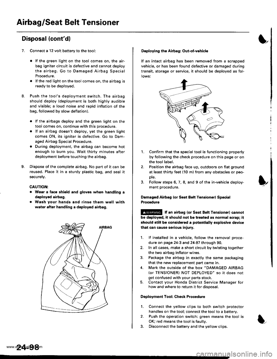
Deploying tho Airbag: Out-ot.vohicle
lf an intact airbag has been removed from a scrapped
vehicle, or has been found defective or damagsd during
transit. storage or seryice, it should be deployed as fol-
lows:
'L Confirm that the special tool is functioning properly
by following the check procedure on this page or on
the tool label.
2. Position the airbag face up, outdoors on flat ground
at least thirty feet (10 m) from any obstacles or peo-
Dte,
3. Follow steps 6, 7, 8. and 9 of the in-vehicle deploy-
ment proceoure.
Dlmaged Airbsg {or Seat Beh Ten3ion6r} Sp6cial
Procgdure
!@ r an airbag {or seat Beh rensioner} cannol
be doployod, it should not be treated as normal scrap; it
should still be considered a pot€ntially explosive device
lhat can cause serious iniury.
1. lf installed in a vehicle. follow the removal proce-
dure on page 24-3 and 24-87 through 90.
2. In all cases, make a short circuit by twisting together
the two airbag inflator wires.
3. Package the airbag in exactly the same packaging
that the new reDlacement Dart came in.
4. Mark the outside of the box "DAMAGED AIRBAG
{or TENSIONER) NOT DEPLOYED" so it does not
get confused with your parts stock.5. Contact your Honda District Service Manager forhow and where to return it for disposal.
Deployment Tool: Check Procedure
Connect the yellow clips to both switch protector
handles on the tool; connect the tool to a battery.
Push the operation switch: green means the tool is
OK: red means the tool is faultv.
Disconnect the baftery and the yellow clips.
I
t
l.
www.emanualpro.com