ECO mode HONDA CR-V 2000 RD1-RD3 / 1.G Workshop Manual
[x] Cancel search | Manufacturer: HONDA, Model Year: 2000, Model line: CR-V, Model: HONDA CR-V 2000 RD1-RD3 / 1.GPages: 1395, PDF Size: 35.62 MB
Page 1351 of 1395
Troubleshooting
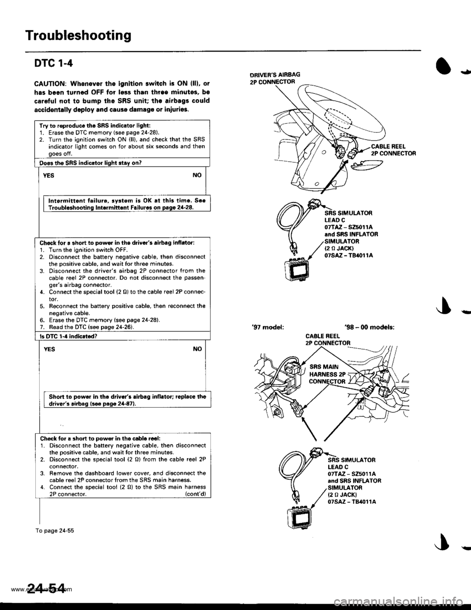
DTC 1-4
CAUTION: Whonover the ignition switch is ON (ll), or
has boen turned OFF for less than throe minutos, bs
carelul nol to bump tho SRS unit; the airbags could
accidentally deploy and cause damago or iniuri63.
ial
ltl
REEL2P CONNECTOR
SIMULATORLEAD C
ffi
07TAZ - SZ5011A.rd SRS INFIATOR
/SIMULATOR./ ea JA0KI
1( otstz-terore
'98 - 00 models:
CABLE REEL
'97 model:
SIMULATORI-EAD C07TAZ - SZ5011Aand SRS INFLATORSIMULATOR(2 0 JACKT07sAz - lB4011A
Try to rop.oduco tho SRS indicator light:1. Erase the DTC momory (soe page 24-28).2. Turn the ignition switch ON {ll}, and check that the SRSindicator light comes on for about six seconds and thengoes off.
Doe3 th6 SRS indicltor light 3tay on?
YESNO
Intormittent tailure, rystem is OK rt this timo. SeeTroubl$hooting Intermittent Failurcs on pago 2G28.
Chack lor a 3hort to powor in ths driyar's airbag inflrtor:1. Turn the ignition swilch OFF.2. Disconnect the battery negative cable, th€n disconnectthe positive cable, and wait for three minutes.3. Disconnect the driver's airbag 2P connector {rom thecable reel 2P connector. Do not disconnect the passen-ger's airbag connector.4. Connect the special tool (2 0) to the cable reel 2P conn6c-tor,5. Reconn€ct the battery positive cable. then reconnect thenegative cable.6. Erase the DTC memory (see page 24-28).7. Read the DTC {see page 24-261.
ls DTC 1-4 indicatod?
NOYES
Short to powe. in the driv.r's rirbrg inflator; replace theddver's airbeq (!o€ D.qa 2447).
Ch€ck for. short to powe. in tho cabl6.ool:1. Disconnect the battery negative cable, then disconnectthe oositive cable, and wait lor three minutes.2. Disconnect the special tool (2 O) from the cable reel 2Pconnefior,3- Remove the dashboard lower cover, and disconnect thecable reel 2P connector lrom the SRS main harness.4. Connect the special tool (2 0) to the SRS ma;n harn€ss2P connoctor. (cont'dl
To page 24-55
24-54
!
www.emanualpro.com
Page 1353 of 1395
Troubleshooting
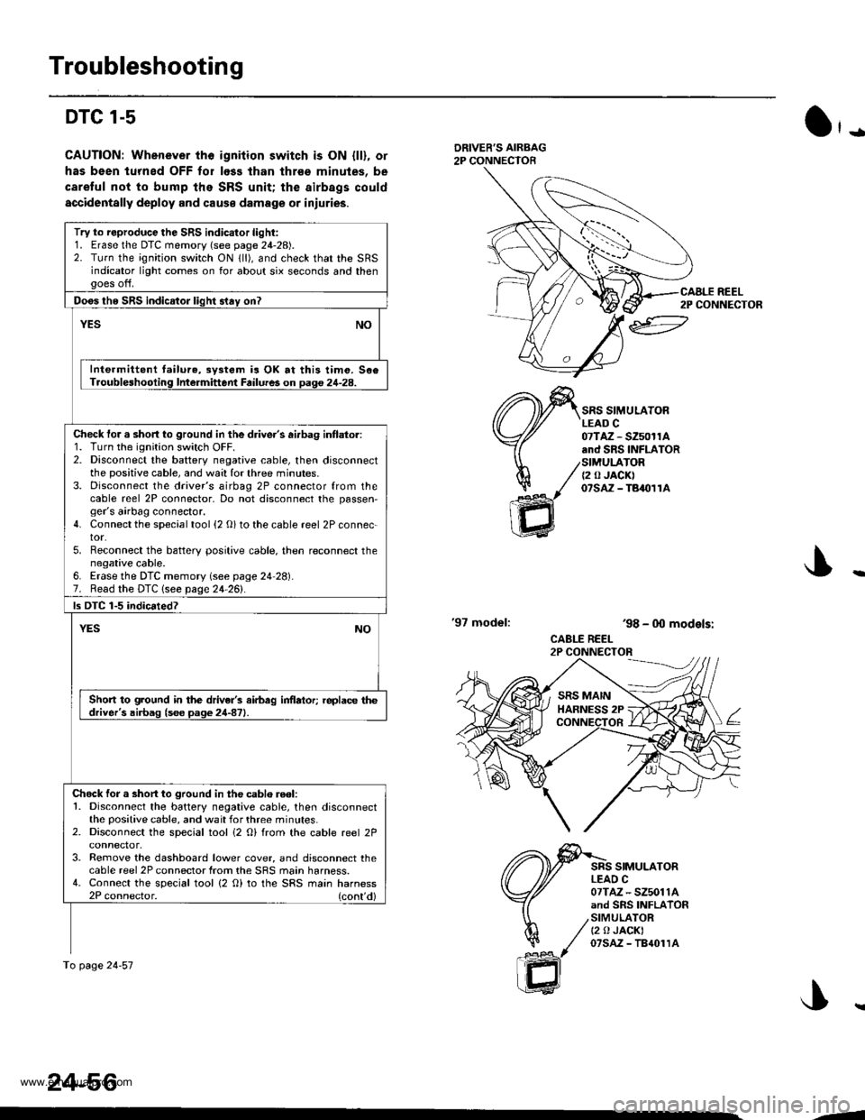
DTC l-s
CAUTION: Whenever tho igniiion switch is ON {ll), or
has been lurned OFF for loss lhan thrse minules, be
caretul not to bump the SRS unit; the airbags could
accidentally deploy and cause damage or iniuries.
O'-
DRIVER'S AIRBAG2P CONNECTOR
'97 model:
SRS SIMULATORLEAD C07TAZ - SZ50r1A.nd SRS INFLATORSIMULATOR{2 0 JACK)07sAz - TBaolrA
SRS SIMULATORLEAO C07TAZ - SZ5011Aand SRS INFLATORSIMULATORt2 0 JACKI07sAz - TB{01rA
ar
h/
ffi
'98 - 0O models:
CABLE REEL2P CONNECTOR
Try to reproduce the SRS indicator light:1. Erase the DTC memory (see page 24-28).2. Turn the ignition switch ON lll), and check that the SRSindicator light comes on for about six seconds and thengoes off.
Doos tho SRS indicator liqht stav on?
YESNO
Inte.mittent tailure,3y3tem is OK at this timo. 506Troubleshooling Intermittent Failures on Daq€ 24-28.
Check tor a short to ground in the driver's ai.bag intlator:1. Turn the ignition switch OFF.2. Disconnect the battery negative cable, then disconnectthe positive cable, and wa:l for three minutes.3. Disconnect the driver's airbag 2P connector from thecable reel 2P connector, Do not disconnect the passen,ger's airbag connector.4. Connect the special tool {2 O} to the cable reel 2P connec-tor.5. Reconnect the battery positive cable. then reconnect thenegative cable.6. Erase the DTC memory (see page 24 28).7. Read the DTC lsee page 24-261.
ls DTC 1-5 indicated?
YESNO
Short to ground in the driver's airbag inflator; replace thedriver's airbag (s6e page 24-871.
Chock for a short to ground in the cablo reel:1. Disconnect the battery negative cable, then disconnectthe positive cable, and wait for three minutes.2. Disconnect the special tool i2 O) from the cable reel 2P
3. Remove the dashboard lower cover, and disconnect thecable reel 2P connector from the SRS main harness.4. Connect the special tool {2 O) to the SRS main harness2P connector. (cont'd)
To page 24-57
24-56
CAALE REEL2P CONNECTOR
J..
.J
www.emanualpro.com
Page 1379 of 1395
Troubleshooting
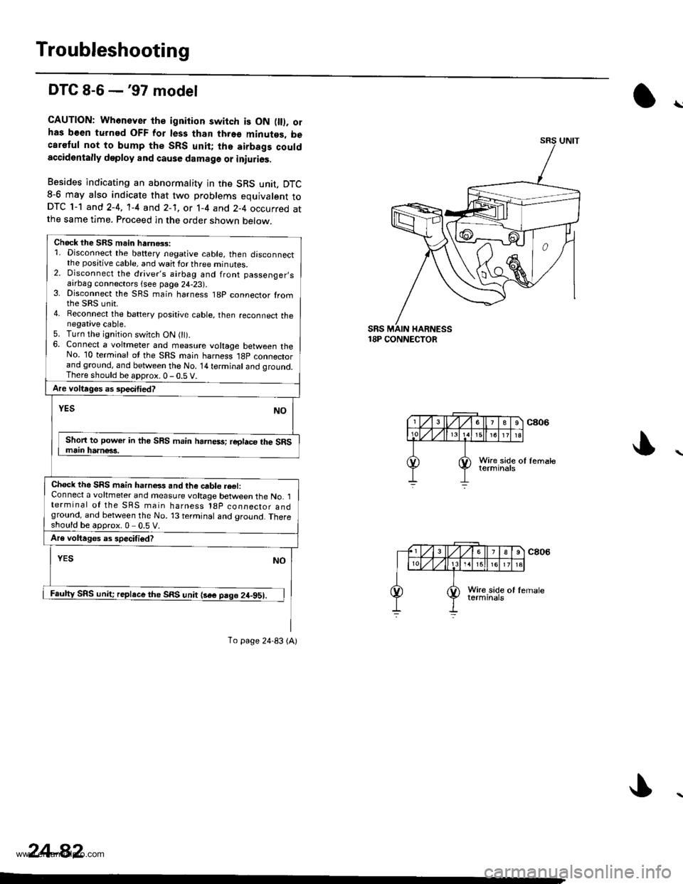
DTC 8-6 -'97 model
CAUTION: Whonever th€ ignition switch is ON fll). olhas b€en turned OFF for les3 than thro€ minutes, becaretul not to bump the SRS unit; tho airbags couldaccidentally deploy and cause damage or iniurios.
Besides indicating an abnormality in the SRS unit, DTC8-6 may also indicate that two problems equivalent toDTC 1-1 and 2-4, 'l-4 and 2-1, or 1-4 and 2-4 occurred atthe same time. Proceed in the order shown below.
18P CONNECTOR
\
Chock the SBS main harnGs:1. Disconnect the battery negative cable, then disconnectthe positive cable, and wait for three minutes.2. Disconnect the driver's airbag and front passenger,safrDag connectors {see page 24-23).3. Disconnect the SRS main harness t8p connector fromthe sRs unit.4. Reconnect the battery posative cable, then reconnect thenegative cable.5. Turn the ignition switch ON 0t).6. Connect a voltmeter and measure voltage between theNo. 10 terminal ot the SRS main harness l8p connectorand ground, and between the No. 14 terminal and qround.There should be aDorox.0-0.5 V.
Are voltages as specitied?
NOYES
Shon to power in tho SRS main harness; reglace the SRSmain harn€63.
Chock the SRS mein harnels and the cable re€l:Connect a voltmeter and measure voltage between the No. 1terminal of the SRS main harness l8p coonector andground, and between the No. 13 terminal and ground. Thereshould be approx.0 0.5 V.
Are voltages as specifiod?
YESNO
Faulty SRS unit; replace the SRS unit {sae pago 24-951.
To page 24-83 (A)
24-82
www.emanualpro.com
Page 1389 of 1395
Gable Reel
Replacement (cont'dl
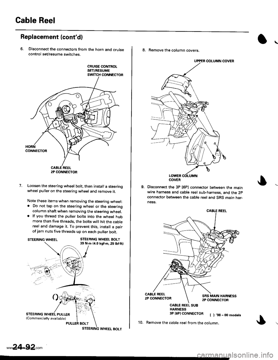
6, Disconnect the connectors from the horn and cruisecontrol sevresume switches.
cRursE coNtRoLSET/RESUMESWITCH CONNECTOR
1.Loosen the steering wheel bolt, then install a steeringwheel puller on the steering wheel and remove it.
Note these items when removing the stee.ing wheel:. Do not tap on the steering wheel or the steeringcolumn shaft when removing the steering wheel,. lf you thread the puller bolts into the wheel hubmore than five threads, the bolts will hit the cablereel and damage it. To prevent this. install a pair
of jam nuts five threads up on each puller bolt.
STEERING WHEEL BOLT39 N.m 14.0 kgf.m. 29 lbf.ftlSTEERING WHEEL
STEERING
2P CONNECTOR
24-92
8. Remove the column covers,
Disconnect the 3P [6P] connector between the mainwire harness and cable reel sub-harness, and the 2pconnector between the cable reel and SRS main har-ness.
CAALE REEL SU8HARNESS3P l6Pl CONNECTOR [ ]:,98_00modets
10. Remove the cable reelfrom the cotumn,
COVER
www.emanualpro.com
Page 1392 of 1395
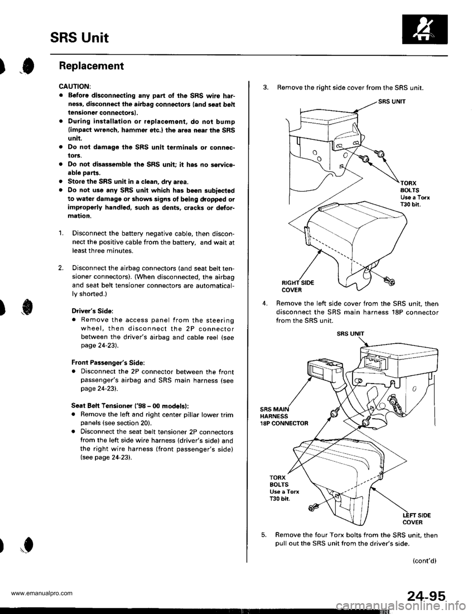
SRS Unit
).0Replacement
CAUTION:
. Before disconnecting any part of the SRS wire har-
nesg, disconnect the airbag connoctors (and soat beh
tensioner connectorsl.
. During installation or replacament, do not bump(impact wrench, hammer etc.) the area near the SRS
unit.
Do not damage the SFS unit terminalg or connsc-
lors.
Do not disassemble the SRS unit it has no saryice-
able parts,
Store the SRS unit in a clean, dry area.
Do not use any SRS unit which has been subiected
to water damage or shows signs ot being dropped orimproperly handlgd, such as dents, cracks or defor-
mation.
Disconnect the battery negative cable, then discon-
nect the positive cable from the battery, andwaitat
least three minutes.
Disconnect the airbag connectors (and seat belt ten-
sioner connectors). (When disconnected, the airbag
and seat belt tensioner connectors are automatical-
ly shorted.)
Driver's Side:
. Remove the access panel from the steering
wheel, then disconnect the 2P connector
between the driver's airbag and cable reel (see
page 24-231.
Front Passenger's Side:. Disconnect the 2P connector between the frontpassenger's airbag and SRS main harness (see
page 24-231.
Soat Beh Tensionor ('98 - 00 modelsr:. Remove the left and right center pillar lower trimpanels (see section 20).
. Disconnect the seat belt tensioner 2P connectors
from the left side wire harness (driver's side) and
the right wire harness (front passenger's side)(see page 24'231.
2.
a
a
'1.
)
)o
24-95
3. Remove the right side cover from the SRS unit.
SRS UNIT
TORXAOLTSUse a TorxT30 bir.
COVER
Remove the left slde cover from the SRS unit. then
disconnect the SRS main harness 18P connector
from the SRS unit.
sRsHARNESS18P CONNECTOR
TORXBOLTSUs€ a TorxT30 bir.
stoECOVER
Remove the four Torx bolts from the SRS unit. then
oull out the SRS unit from the driver's side.
(cont'd)
www.emanualpro.com
Page 1393 of 1395
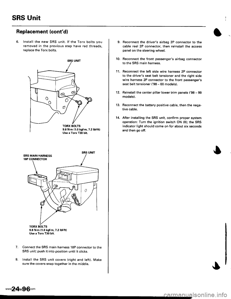
SRS Unit
Replacement (cont'dl
6. lnstall the new SRS unit. lf the Torx bolts you
removed in the previous step have red threads,
replace the Torx bolts.
TORX BOLTS9.8 N.m 11.0 kgf.m,7.2 lbtft)Uso a Torx T30 bit.
Connect the SRS main harness l8P connector to the
SRS uniu push it into position until it clicks.
Install the SRS unit covers (right and left). Make
sure the covers snap together in the middle.
7.
8.
TORX BOLTS9.8 N.m {1.0 kgf.m, ?.2Use . Torx T30 bh,
SRS UNIT
24-96
-
9. Reconnect the driver's aibag 2P connector to the
cable reel 2P connector, then reinstall the access
panel on the steering wheel.
Reconnect the front passenger's airbag connector
to the SRS main harness.
Reconnect the left side wire harness 2P connector
to the driver's seat belt tensioner and the right side
wire harness 2P connector to the front passenger's
seat belt tensioner ('98 - 00 models).
Reinstall the center pillar lower trim panels {'98 - 99
modelsl.
Reconnect the battery positive cable, then the nega-
tive cable.
After installing the SRS unit, confirm proper system
operation: Turn the ignition switch ON (ll); the SRS
indicator light should come on for about six seconds
and then go off,
10.
1't.
12.
13.
14.
www.emanualpro.com