ECO mode HONDA CR-V 2000 RD1-RD3 / 1.G Workshop Manual
[x] Cancel search | Manufacturer: HONDA, Model Year: 2000, Model line: CR-V, Model: HONDA CR-V 2000 RD1-RD3 / 1.GPages: 1395, PDF Size: 35.62 MB
Page 885 of 1395
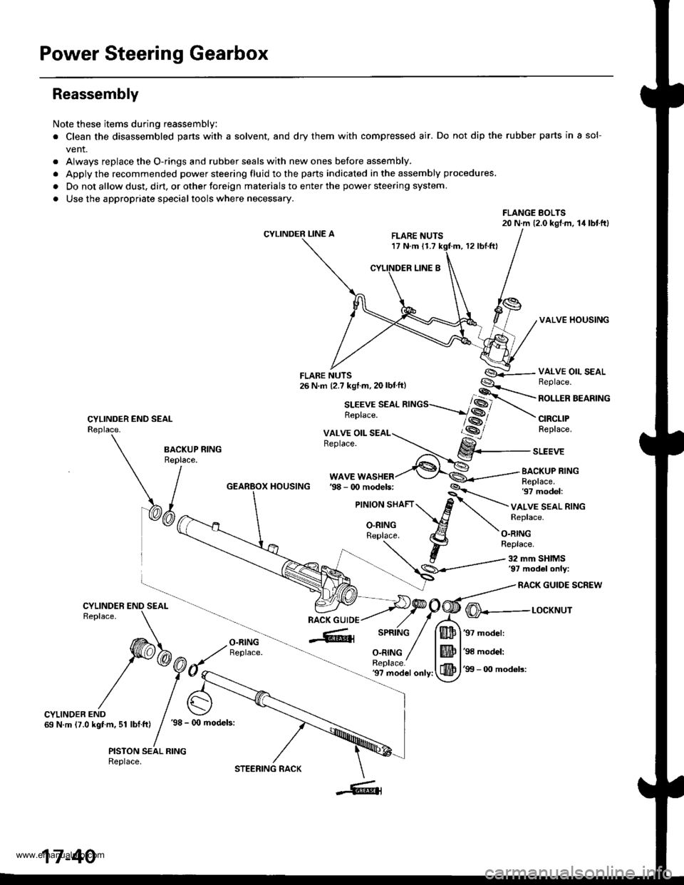
Power Steering Gearbox
Reassembly
Note these items during reassembly
. Clean the disassembled parts with a solvent, and dry them with compressed air. Do not dip the rubber parts in a sol-
vent.
. Always replace the O-rings and rubber seals with new ones before assembly.
. Apply the recommended power steering fluid to the parts indicated in the assembly procedures.
. Do not allow dust. dirt, or other toreign materials to enter the power steering system.
. Use the appropriate specialtools where necessary.
FLANGE BOLTS20 N.m (2.0 kgl.m, 14lbtftl
CYLINDER LINE AFLARE NUTS17 N.m 11.712 rbl.ftl
VALVE HOUSING
CYLINDER END SEALReplace.
VALVE OIL SEALBeplace.
ROLLER BEARING
CIRCLIPReplace.
BA.KUP RING
\/^"
WAVE WASHERBACKUP RINGReplace.97 model:HOUSING
VALVE SEAL RINGReplace.
O.RINGReplace.
32 mm SHIMS'97 mod6l only:
RACK GUIDE SCREW
O-RINGReplace.
@---r-ocxr'rur
'97 model:
'98 model:
'99 - 0O mod6ls:'9? model only:
CYLINDER END69 N.m (7.0 kgf.m, 51 lbf.ft)'98 - (x) models:
PISTON SEAL RINGReplace.
17-40
STEERING RACK
www.emanualpro.com
Page 898 of 1395
't 4.
15.
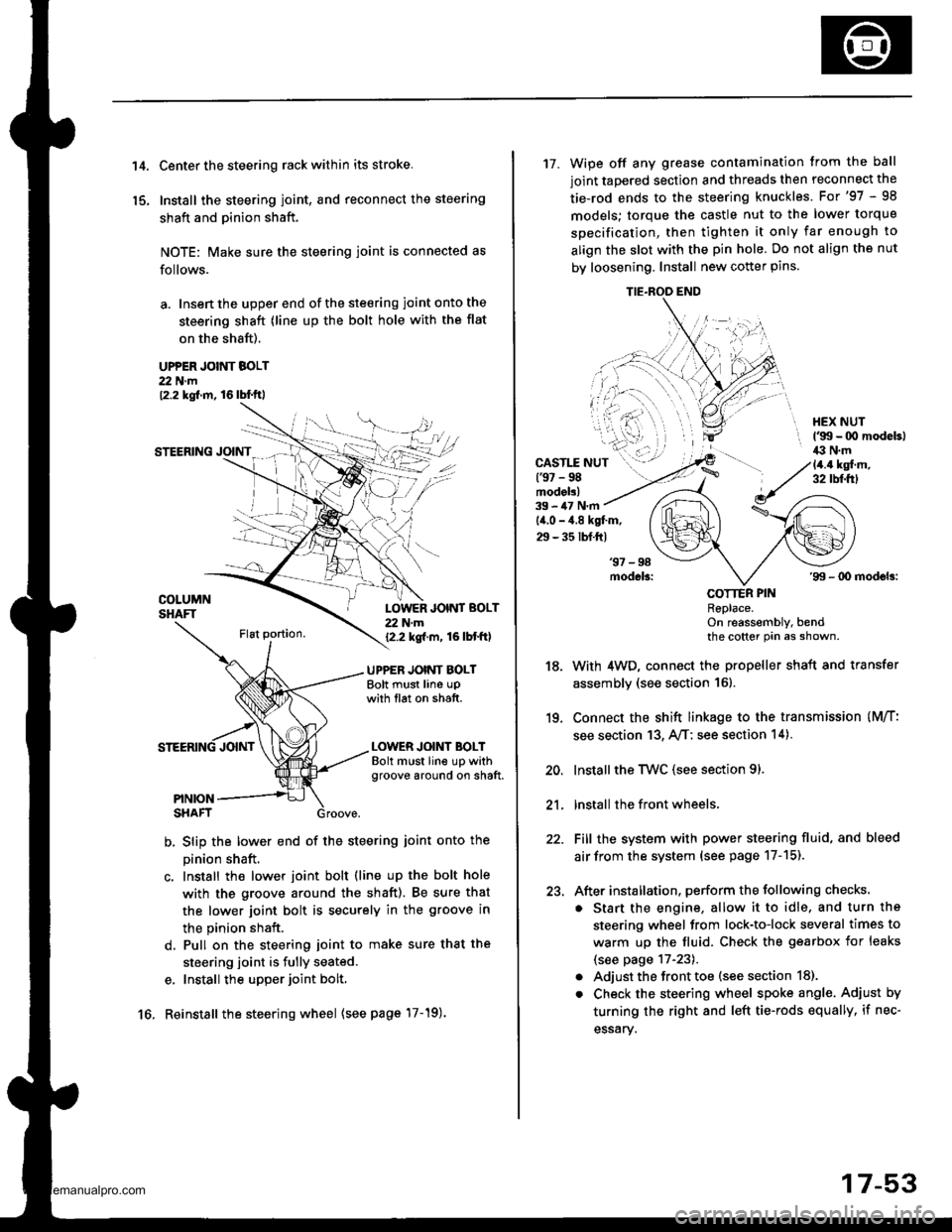
Center the steering rack within its stroke.
Install the steering joint, and reconnect the steering
shaft and pinion shaft.
NOTE: Make sure the steering joint is connected as
follows.
a. Insen the upper end of the steering joint onto the
steering shaft (line up the bolt hole with the flat
on the shaft).
UPPER JOINT BOLT22 N.m12.2 kgf.m, 16lbl.ft,
STEERING JOINT
COLUMNSHAFTLOWER JOINT BOLT22 N.m12.2 kgf.m, 16lbtftl
UPPER JOINT BOLTBolt must line upwith tlat on shatt.
LOWER JOINT BOLTBolt must line up withgroove around on shaft.
PINIONSHAFT
b, Slip the lower end of the steering ioint onto the
pinion shaft.
c. Install the lower joint bolt (line up the bolt hole
with ths groove around the shaft). Be sure that
the lower joint bolt is securely in the groove in
the pinion shaft.
d. Pull on the steering joint to make sure that the
steering joint is fully seated.
e, Install the upper joint bolt,
Reinstall the steering wheel {see page'17-19).16.
17-53
17. Wipe off any grease contamination trom the ball
joint tapered section and threads then reconnect the
tie-rod ends to the steering knuckles. For'97 - 98
models; torque the castle nut to the lower torque
specification, then tighten it only far enough to
align the slot with the pin hole. Do not align the nut
by loosening. Install new cotter pins.
CAST1T NUT(9t - 98modol!)
HEX NUTl'g!t - 00 modeb)il:l N.m14.4 ksl.m,32 tbf.f0
39 - iU N'm
lil.o - 4.8 kgl.m,
29 - 35 tbf.ftl
18.
19.
20.
21.
22.
23.
'99 - lD modeb:
COTTER PINRePlace.on reassembly, bendthe cotter Pin as shown.
With 4WD, connect the propeller shaft and transfer
assembly (see section 16).
Connect the shift linkage to the transmission (M/T:
see section 13, A,/T; see section 14).
Installthe Twc (see section 91.
lnstall the front wheels,
Fill the system with power steering fluid, and bleed
air from the system (see page 17-15).
After installation. perform the following checks.
. Start the engine, allow it to idle, and turn the
steering wheel from lock-to-lock several times to
warm up the fluid. Check the gearbox for leaks
(see page 17-23).
. Adjust the front toe (s€e section 18).
. Check the steering wheel spoke angl€. Adjust by
turning the right and left tie-rods equally, if nec-
essary.
TIE.ROO END
www.emanualpro.com
Page 959 of 1395
Troubleshooting Precautions
ABS lndicalor
1 lf the system is oK, the ABS indicator goes off two seconds after turning the ignition switch oN 1l) wathout staningthe engine, and then comes on again and goes off after two seconds. This occurs because the ABS control unit isturned on by the lG2 power source.2. The ABS indicator comes on when the ABS control unit detects a problem in the system. However, even thouoh thesystem is operating properly, the ABs indicator will come on too, under the following conditions:. Signal disturbance
. Wheel spin
. Only drive wheels rotate. Battery voltage fluctuates
To determine the actual cause of the problem, question the customer about the problem, taking these conditions intoconsideration:
3 When a problem is detected and the ABS indicator comes on, the indicator can stay on until the ignition switch isturned OFF, or it can automatically go off, depending on the mode.. Indicator stays on untilthe ignition switch is turned off: When the system is in the system down mode.. Indicator automatically goes off: When the system is in the control inhibition mode.4 The ABS indicator stays on when the system is reactivated without erasing the DTC, but it goes off after starting thevehicle.
When the wheel sensor system is faulty and the ABS indicator comes on. the algorithm of the system automatically turnsoff the ABS indicator after the wheel speed signal returns to the normal speed. Also, when the DTc is erased, the cpu isreset and the ABS indicator goes off when the system checked out normal by the initial diagnosis.Therefore, test-drive the vehicle after servicing the wheel sensor system. and be sure that the ABS indicator does notcome on.
5 When the ABS control unit outputs battery voltage to the gauge assembly, the ABS indicator ooes off.
Diagnostic Trouble Code (DTCI
1. The diagnostic trouble code (DTc) is memorized when a problem is detected and the ABS indicator does not go off,or when the ABS indicator comes on.The DTc is not memorized when the ABS indicator comes on unress the cpu is activated,2 The memory can hold any number of DTCs. However, when the same DTc is detected twice or more, the tater one iswritten over the old one.
Therefore, when the same problem is detected repeatedly, it is recorded as one DTC.3. The DTCs are indicated in the order of ascending number, not in the order they occur.4. The DTCS are memorized in the EEPROM (non-volatile memorv).Therefore, the memorized DTcs cannot be canceled by disconnecting the battery. perform the specified procedures toerase the DTCS.
Self-diagnosis
1. Self-diagnosis can be classified into these four categories:' Initial diagnosis: Performed right after the eng ine starts and untir theABS indicator goes off.. Except ABS control: Performed when the ABS is not functioning.. During ABS control: Performed when the ABS is functioning.. During warning: Performed when the ABS indicator is ON.2. The system performs the fo|owing contrors when a probrem is detected by the serf-diagnosis:. ABS indicator ON. Memorv of DTC. Mode changetothe "system down mode,, or the ,,control inhibition mode,,.
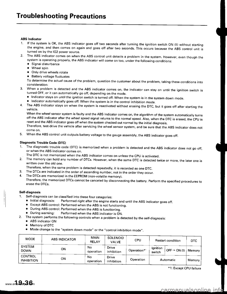
MODEABS INDICATORMAIN
RELAY
SOLENOID
VALVECPURestart conditionDTC
SYSTEM
DOWNONNo
operation
Drive
inhibitionOperation*rlgnition
switchoFF - ON l)Memory
CONTROL
INHIBITIONONNo
operal|on
Drive
inhibitionOperationAutomaticlMemory
*1: Except CPU failure
19-36
www.emanualpro.com
Page 961 of 1395
Diagnostic Trouble Code (DTC)
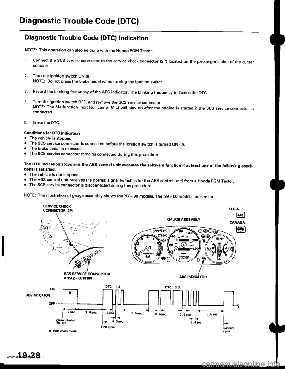
Diagnostic Trouble Gode IDTCI Indication
NOTE: This operation can also be done with the Honda pGM Tester.
1. Connect the SCS service connector to the service check connector (2P) located on the passenger's side of the centerconsote.
2. Turn the ignition switch ON (ll).
NOTE; Do not press the brake pedal whenturningthe ignition switch.
3 Record the blinking frequency of the ABS indicator. The brinking frequency indicates the DTc.
4. Turn the ignition switch OFF. and remove the SCS service connector.NOTE: The Malfunction Indicator Lamp (MlL) will stay on after the engine is startsd if the SCS seryica connecror rsconnected.
5. Erase the DTC.
Conditions for DTC indication. The vehicle is stopped.. The SCS service connector is connected before the ignition switch is turned ON flt).. The brake pedal is released.. The SCS service connector remains connected during this procedure.
The DTC indication stops and the ABS control unit axecutos tha softwaro lunction if at least one of tho following condi-tions i3 satisfiod:
. The vehicle is not stoooed.. The ABS control unit receives the normal signal (which is for the ABS control unit) from a Honda pGM Tesrer.. The SCS service connector is disconnectod during this procedure.
NQTE: The illustration of gauge assembly shows the '97 - 98 models. The '99 - oo models are similar.
SEFVICE CHECKCONNESTOR I2P}
GAUGE ASSEMBLY
A8S II{DEATOR
u.s.A.
@
CANADA
@
19-38
www.emanualpro.com
Page 1101 of 1395
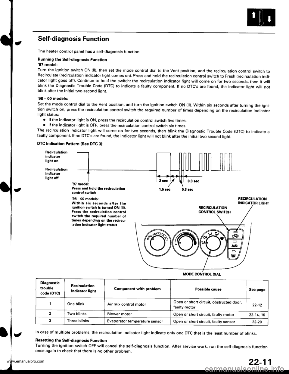
Self-diagnosis Function
The heater control panel has a self-diagnosis function.
Running the Self-diagnosis Function'97 mod€l:
Turn the ignition switch ON {ll), then set the mode control dial to the Vent position, and the recirculation controt switch toRecirculate {recirculation indicator light comes on). Press and hold the recirculation control switch to Fresh (recirculation indi-cator light goes off). Continue to hold the switch; the recirculation indicator light will come on for two seconds. then it willblink the Diagnostic Trouble Code (DTC) to indicate a iaulty component. lf no DTC'S are found, the indicator liqht will notblink atter the initial two second light.
'98 - 00 models:
Set the mode control dial to the Vent position, and turn the ignition switch ON (ll). Within six seconds after turning the igni-tion switch on, press the recirculation control switch the required number of times depending on the recirculation indicatorlight status:
.lftheindicatorlightisON,presstherecirculationcontrol switch five times..lftheindicatorlightisOFF,presstherecirculationcontrol switch six I|mes.The recirculation indicator light will come on for two seconds, then blink the Diagnostic Trouble Code (DTC) to indicate afaulty component. lf no DTC'S are found, the indicator light will not blink after the initial two second liqht.
DTC Indicaiion Pattern {See DTC 3}:
Rocirculationindicatorlight on
Recirculrtionindicatorlighi off'97 model:P.ess and hold th6 recircul.tioncontrol switch'98 - 00 modek:Within six second3 atter theignition switch b turned ON (lll.Prass the rocirculation controlswitch the required number oltimes depending on the r6circu-lation indicator light striu3
,r*
/1.5 aaa 0.3 aac
RECIRCULANONINDICATOR LIGHT
In case of multiple problems, the recirculation indicator light indicate only one DTC that is the least number of blinks.
Resetiing the Solf.diagnosis Funqtion
Turning the ignition switch OFF will cancel the self-diagnosis function. After service work, run the self-diaqnosis functiononce again to check that there is no other Droblem.
MODE CONTROL OIAL
Diagnostic
trouble
code {DTCI
R6circulation
indicator lightComponent with problsmPossiblo causcSee page
'lOne blinkAir mix control molorOpen or short circuit, obstructed door,
faulty motor22-12
2Two blinksElower motorOpen or short circuit, faultv motor22-14,16
Three blinksEvaporator temperature sensorOpon or short circuit, faulty sensor22-20
t
www.emanualpro.com
Page 1112 of 1395
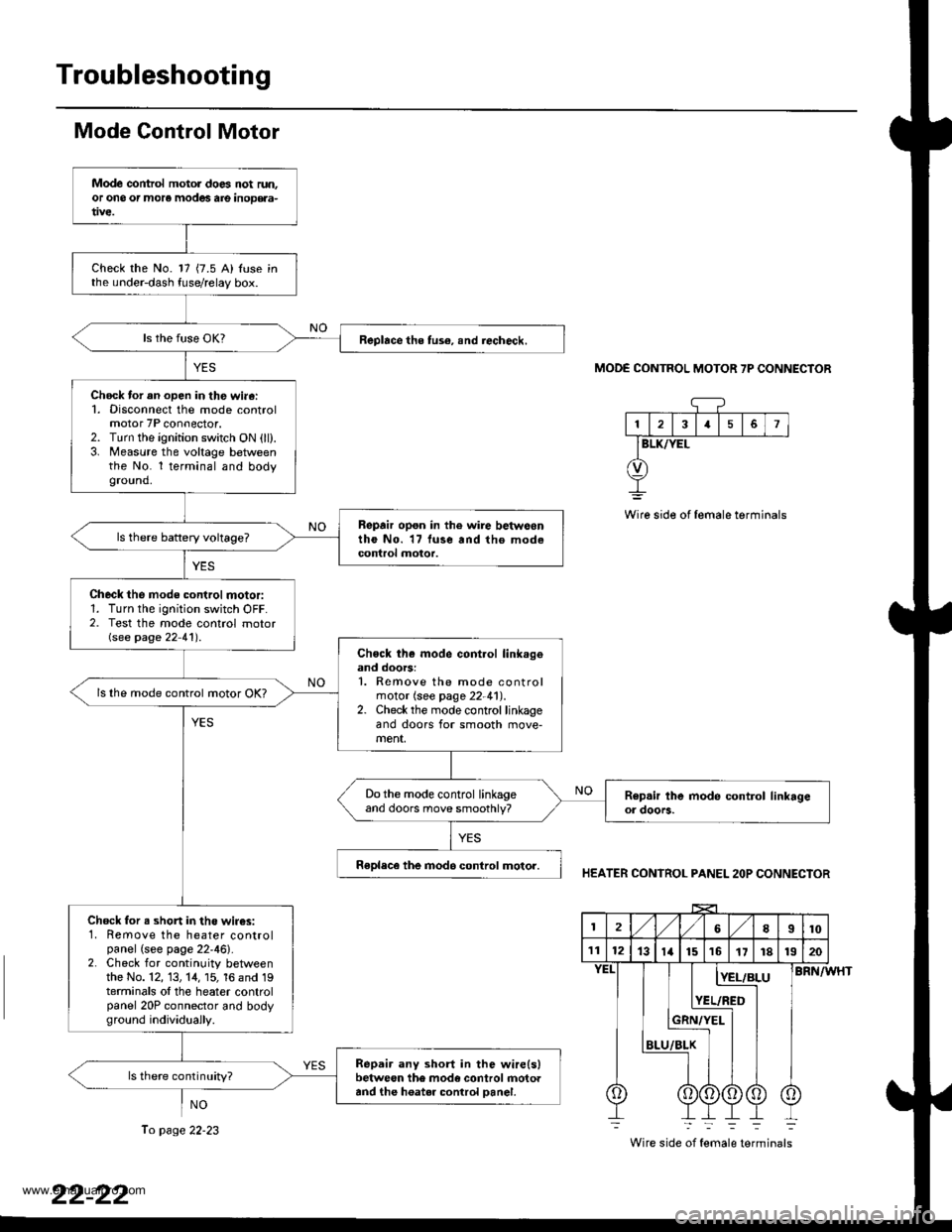
Troubleshooting
Mode Control Motor
NO
MODE CONTROL MOTOR 7P CONNECTOR
13I5
BLK/YEL
Wire side of female terminals
HEATER CONTROL PANEL 2OP CONNECTOR
BRN/WHT
Wire side of female terminals
Mode control motol does not run.or ono or more modes are inoD€aa-
Check the No. 17 {7.5 A) Iuse inthe under-dash fuse/relay box.
Replace the tus€, snd iecheck.
Chock tor an open in th€ wi.6:1. Disconnect the mode controlmotor 7P connector.2. Turn the ignition switch ON (ll).3. Measure the voltage betweenthe No. l terminal and bodyground.
Repair opon in the wire betwoontho No. 17 luse and tho modecontrol motor.
Check the mode control motor:1. Turn the ignition switch OFF.2. Test the mode control motorGee page 22 41') .
Chock th€ mode cont.ol link.geand doors:1. Remove the mode controlmotor (see page 22-41).2. Check the mode control linkageand doors for smooth move-ment,
ls lhe mode control motor OK?
Do the mode control linkageand doors move smoothly?
Replece the inod6 control motor.
Chock for s shon in the wir€s:1. Remove the heater controlpanel (see page 22'46).2. Check for continuity betweenthe No. 12, 13, 14, 15, 16 and 19terminals ol the heater controlpanel 20P connector and bodyground individuaily.
Repair any short in the wire(slbetween the mode control rnotoaand the h6ater control Danel.
ls there continuity?
2l,/1,/8I10
111213ta151617r81320
BLU
[E!r!
YEL/RED
Ii
To page 22-23
www.emanualpro.com
Page 1127 of 1395
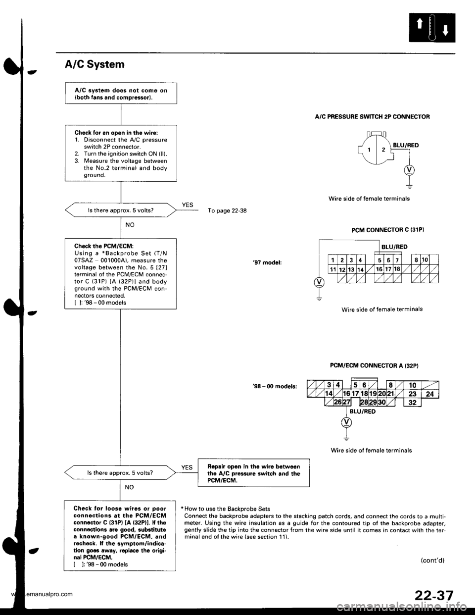
A/C aystem does not come on{both fans and comDrossor).
Ch6ck lor .n open in the wire:1. Disconnect the A,/C pressureswitch 2P connector.2. Turn the ignition switch ON (ll).
3. Measure the voltage betweenthe No.2 terminal and bodyground.
ls there approx. 5 volts?
check tho PcM/EcM:Using a *Backprobe Set (T/N
07SAZ 0010004). measure thevoltage between the No.5 t27lterminal of the PCM/ECM connec,tor C (31P) [A 132P)l and bodyground with the PCM/ECM con-nectors connected,I l: '98 - 00 models
Rop.ir open in th6 wire botweonthe A/C Dr*sure switch and thePCM/ECM.
ls there approx.5 volts?
Check tor loo3e wires or Doorconnections at the PCM/ECMconnoctor C l3lPl lA (32Pll. It theconnections arg good, 3ubdtitut€a known-good PCM/ECM, andrecheck. ll the 3ymptom/indica-tion go.. eway, r€placo thG origi-nal PCM/ECM,[ ]: '98 -00 models
A/C System
A/C PRESSURE SWITCH 2P CONNECTOR
fo page 22-38
PCM CONNECTOR C (31PI
'97 modol:
Wire side of female terminals
PCM/ECM CONNECTOR A I32P'
38 - 00 modeb:
Wire side of female terminals
* How to use the Backprobe SetsConnect the backprobe adapters to the stacking patch cords, and connect the cords to a multi-meter. Using the wire insulation as a guide for the contoured tip ol the backprobe adapter,gently slide the tip into the connector from the wire side until it comes in contact with the ter.minalond olthe wire (see section 11).
(cont'd)
22-37
www.emanualpro.com
Page 1146 of 1395
A/G System Service
Performance Test
The performance test will helD determine if the air con-
ditioner system is operating within specifications.
Use only service equipment that is U.L.-listed and is cer-
tified to meet the requirements of SAE J2210 to remove
HFC-134a (R-134a) from the air conditioner svstem.
CAUTION: Exposure to air condiiioner r€trigerant and
lubricant vapor or mist can irritate €yes, nose and
throat. Avoid bre8thing the air conditioner retrige.ant
and lubricant vapor or mist,
lf accidental system discharge occurs. ventilate work
area before resuming service.
R-134a service equipment o. vehicle air conditioner sys-
tems should not be pressure tested or leak tested with
comDressed air.
@ some mixtur€s ol air and R-134a have becn
shown to be combuslible at olsvated pressures and can
result in lire or explosion causing iniury or property
damage. Never use compressed air to prgssure test R-
13i[a service equipment or vehicle air conditioner sys.
tems.
Additional health and safety information may be obtained
from the refrigerant and lubricant manufacturers.
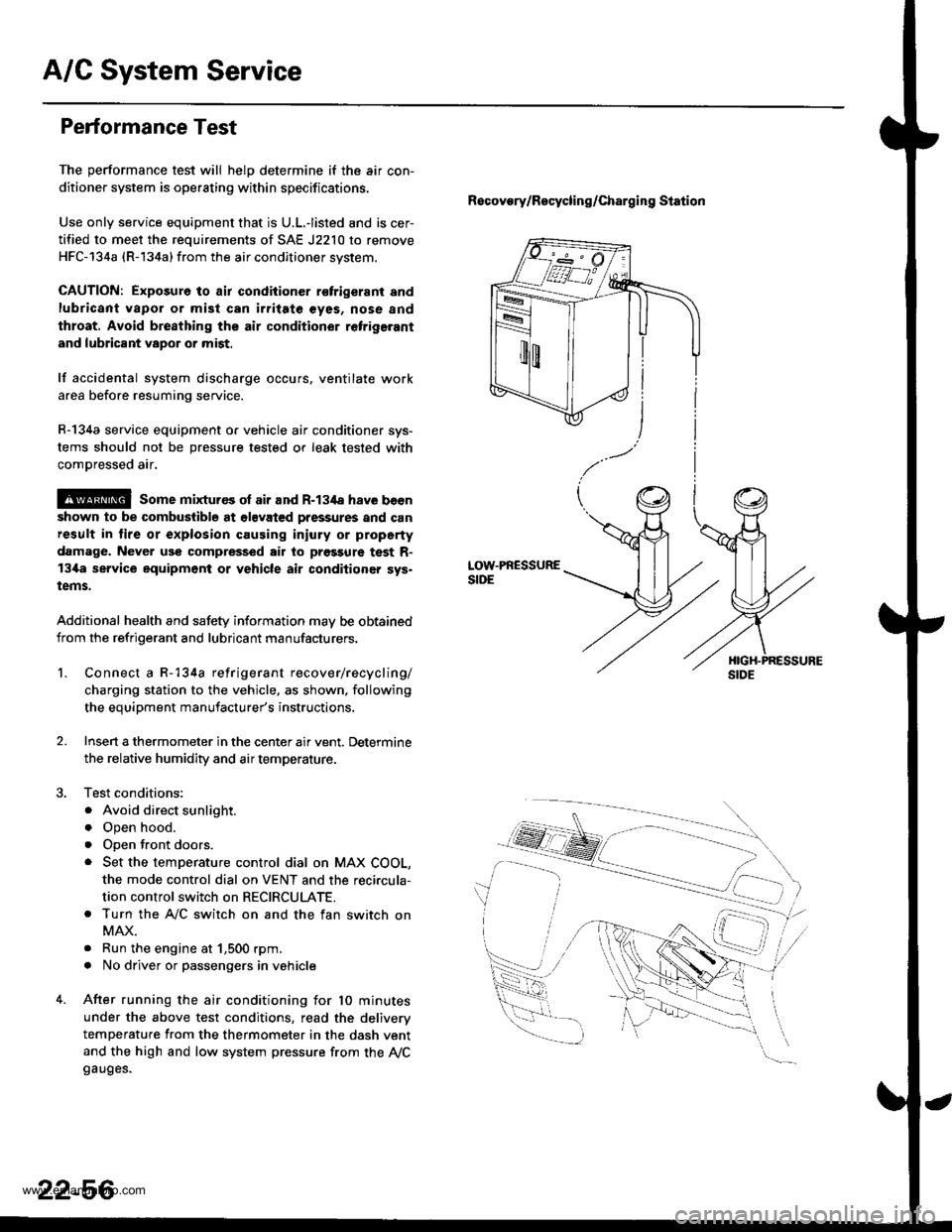
Recovory/Recycling/charging station
LOW.PRESSURESIDE
1.Connect a R-134a refrigerant recover/recycling/
charging station to the vehicle, as shown. following
the equipment manufacturer's instructions,
Insen a thermometer in the center air vent. Determine
the relative humidity and air temperature.
Test conditions:
. Avoid direct sunlight.
o Open hood.
. open front doors.
. Set the temperature control dial on MAX COOL,
the mode control dial on VENT and the reci.cula-
tion control switch on RECIRCULATE.
. Turn the A,/C switch on and the fan switch on
MAX.
. Run the engine at 1,500 rpm.
. No driver or passengers in vehicle
After running the air conditioning for 10 minutes
under the above test conditions, read the deliverv
temperature from the thermometer in the dash vent
and the high and low system pressure from the Ay'Cgauges.
2.
22-56
www.emanualpro.com
Page 1158 of 1395
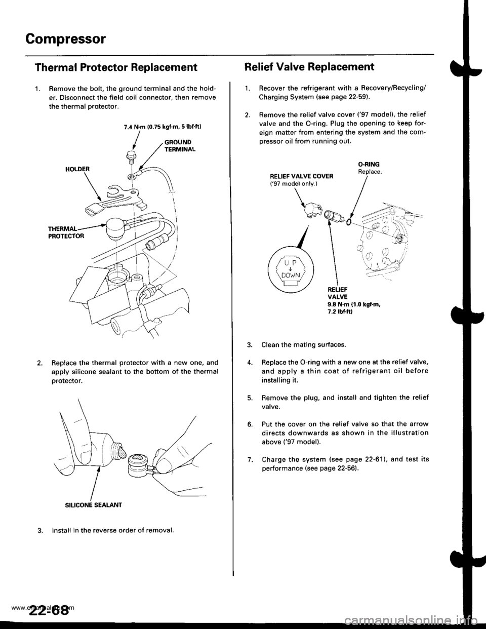
Compressor
Thermal Protector Replacement
1. Remove the bolt, the ground terminal and the hold-
er. Disconnect the field coil connector. then remove
the thermal Drotector.
7.4 N.m (0.75 kgrf.m,5lbf ftl
GROUNDTERMINAL
ReDlace the thermal protector with a new one, and
apply silicone sealant to the bottom of the thermal
orotector,
3. lnstall in the reverse order of removal.
SILICONE SEALANT
22-68
Relief Valve Replacement
l.Recover the refrigerant with a Recovery/Recycling/
Charging System (see page 22-59).
Remove the relief valve cover ('97 model), the relief
valve and the O-ring. Plug the opening to keep for-
eign matter from entering the system and the com-
pressor oil from running out.
O.RINGReplace.
RELIEFVALVE9.8 N.m {1.0 hgf.m,7.2 rbr.ftl
Put the cover on the relief valve so that the arrow
directs downwards as shown in the illustration
above ('97 model).
Clean the mating surfaces.
Replace the O-ring with a new one at the relief valve,
and apply a thin coat of refrigerant oil before
installing it.
Remove the plug. and install and tighten the relief
valve.
7. Charge the system (see page 22-61), and test its
performance (see page 22-561r.
www.emanualpro.com
Page 1165 of 1395
Five-step Troubleshooting
1.
3.
Verify The Complaint
Turn on all the components in the problem circuit to
verify the customer complaint. Note the symptoms.
Do not begin disassembly or testing until you have
narrowed down the problem area.
Analyze The Schematic
Look up the schematic for the problem circuit.
Determine how the circuit is supposed to work by
tracing the current paths from the power feed
through the circuit components to ground. lf several
circuits fail at the same time, the fuse or ground is a
likely cause,
Based on the symptoms and your understanding of
the circuit operation, identify one or more possible
causes of the problem.
lsolate The Problem By Testing The Circuit
Make circuit tests to check the diagnosis you made
in step 2. Keep jn mind that a logical, simple proce-
dure is the key to efficient troubleshooting. Test for
the most likely cause of failure first. Try to make
tests at points that are easily accessible,
Fix The Problem
Once the specific problem is identified, make the
repair. Be sure to use proper tools and safe proce-
dures.
Make Sure The Circuit Works
Turn on all components in the repaired circuit in all
modes to make sure you've fixed the entire prob-
lem. lf the problem was a blown fuse, be sure to
test all of the circuits on the fuse. lvlake sure no new
problems turn up and the original problem does nol
recur.
4.
O
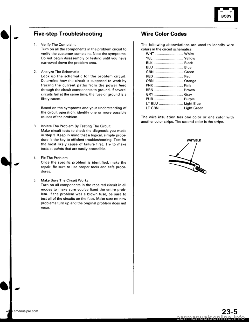
Wire Color Codes
The following abbreviations are used to identify wire
colors in the circuit schematics:
WHT ............................. White
YEL,.............................. Yellow
BLK ..........,................... Black
BLU .............................. Blue
GRN .............................Green
RED .............................. Red
ORN .............................Oran9e
PNK.....,........................ Pink
BRN .............................. Brown
GRY .............................. Gray
PUR .........,.................... Purple
LT BLU ..................,...... Light Blue
LT GRN ........................ Light Green
The wire insulation has one color or one color with
another color stripe. The second color is the stripe.
WHT/BLK
www.emanualpro.com