Hose HONDA CR-V 2000 RD1-RD3 / 1.G User Guide
[x] Cancel search | Manufacturer: HONDA, Model Year: 2000, Model line: CR-V, Model: HONDA CR-V 2000 RD1-RD3 / 1.GPages: 1395, PDF Size: 35.62 MB
Page 103 of 1395
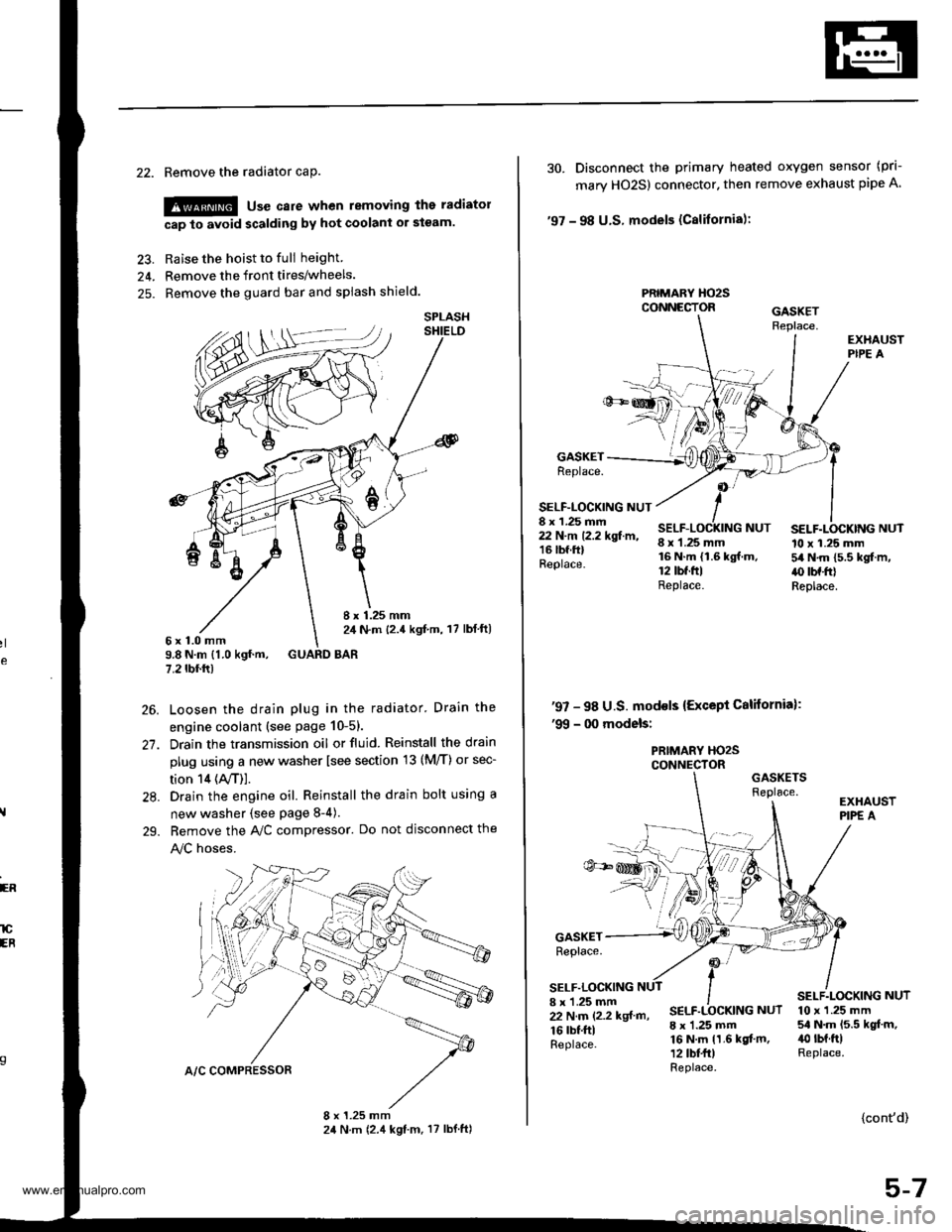
22. Remove the radiator caP.
!@ use care when removing the radiatol
cap to avoid scalding by hot coolani or steam.
23. Raise the hoist to full height
24. Remove the front tires/wheels.
25. Remove the guard bar and splash shield.
8 x 1.25 mm2,1 N.m {2.4 kgf,m, 17 lbl ft)6x1.0mm9.8 N.m {1.0 kgf.m, GUARD BAR7.2 tbf.rr)
Loosen the drain plug in the radiator. Drain the
engine coolant (see page 10-51.
Drain the transmission oil or fluid. Reinstall the drain
plug using a new washer lsee section 13 (M/T) or sec-
tion 14 (ly'T)].
Drain the engine oil. Reinstall the drain bolt using a
new washer {see page 8-4).
Bemove the A,/C compressor. Do not disconnect the
!y'C hoses.
SPLASH
26.
27.
28.
29.
ER
lCEB
30. Disconnect the primary heated oxygen sensor (prl-
mary HO2S) connector. then remove exhaust pipe A
'97 - 98 U.S. models (Cslifornia):
PRIMARY HO2SCONNECTOR
GASKETReplace.
SELF-LOCKING NUT8 x 1.25 mm22 N.m 12.2 kgf.m,16 lbf.ftlReplace.
8 x 1.25 mm16 N.m {1.6 kgf.m.12 tbt.ftlReplace.
SELF.LOCKING NUT10 x 1.25 mm54 N.m 15.5 kgf.m,.() tbf.frlReplace.
NUT
'97 - 98 U.S. mod€ls {Except California):'99 - 00 models:
PRIMARY HO2SCONNECTORGASKETSReplace.
GASKETReplace.
SELF.LOCKING8 x 'l.25 mm22 N.m (2.2 kgf m,
16 rbf.ftlReplace.
SELF.LOCKING NUT
8 x 1.25 mm16 N.m 11.6 kgf.m,12 tbt fr)Replace.
10 x 1.25 mm54 N.m 15.5 kgt.m,40 rbt.ftlReplace.
{cont'd)
5-7
www.emanualpro.com
Page 105 of 1395
rd
te
n-
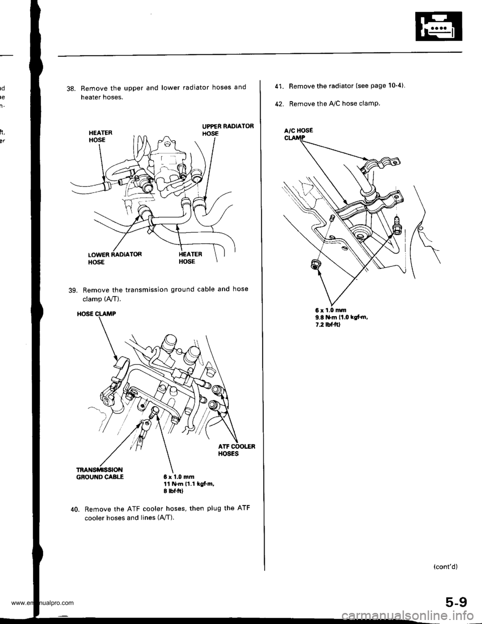
38. Remove the upper and lower radiator hoses and
heater hoses.
39. Remove the transmission ground cable and hose
clamp (A,/T).
GBOUI{DCABLE 6x 1,0 mm11 N.m 11.1 lof'm,I tbf.ftl
40. Remove the ATF cooler hoses, then plug the ATF
cooler hoses and, n"" lAfI).
rt,
BT
6xl,0mm
A/C HOSE
41.
42.
Remove the radiator (see page 10"4).
Remove the IVC hose clamp.
9.8 'm lt.o klt m,l.2tutal
(cont'd)
5-9
www.emanualpro.com
Page 107 of 1395
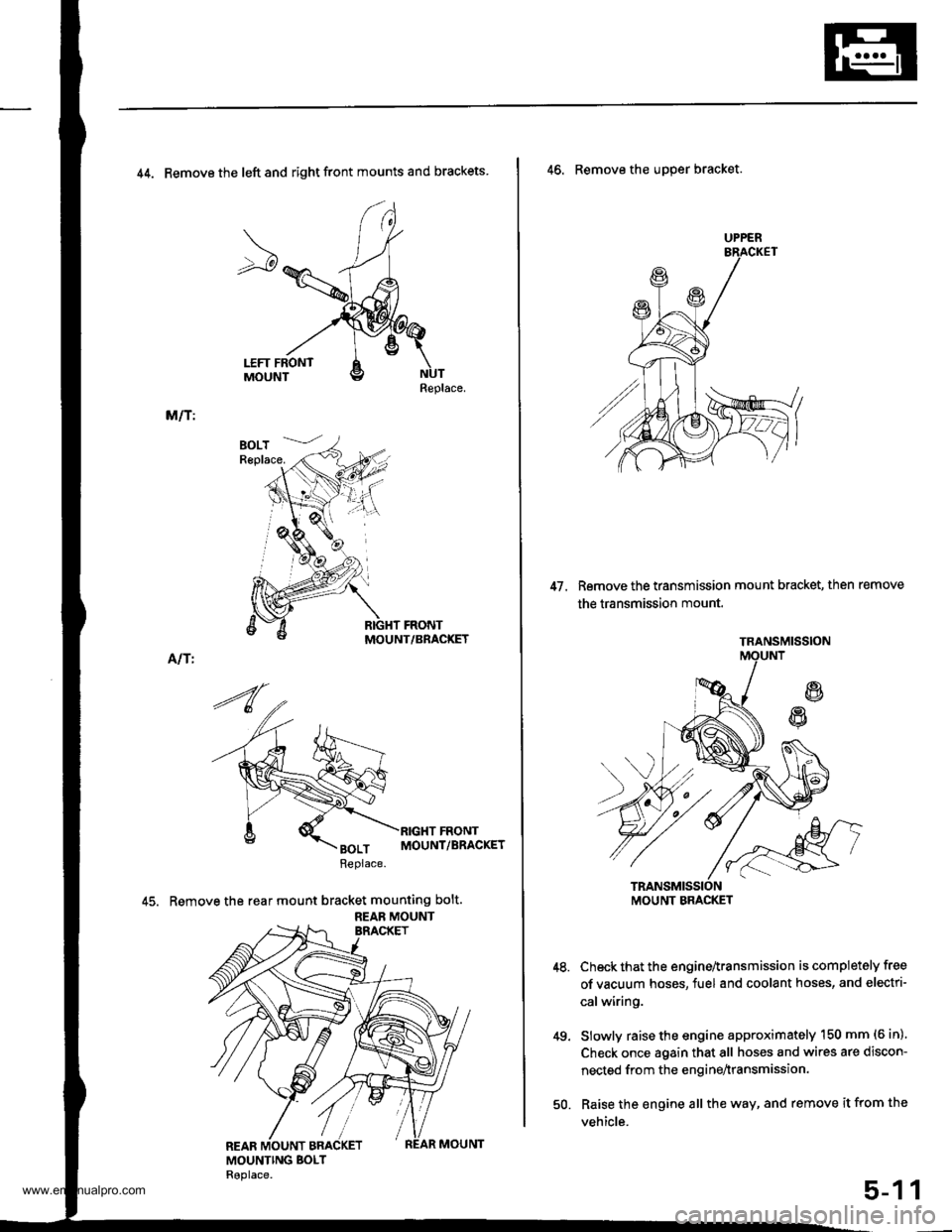
44. Remove the left and right front mounts and brackets
Replace.
M/T:
MOUNT/BRACKET
Alf I
45. Remove the rear mount bracket mounting bolt.
REAB MOUNT
UPPER
47. Remove the transmission mount bracket, then remove
the transmission mount.
46. Remove the uDper bracket.
Check that the engine^ransmission is completely free
of vacuum hoses, fuel and coolant hoses, and electri-
calwiring.
Slowly raise the engine approximately 150 mm (6 in)'
Check once again that all hoses and wires are discon-
nected from the enginenransmission.
Raise the engine all the way, and remove it from the
vehicle.
49.
1
TRANSMISSION
MOUNT BMCKET
50.
5-1
www.emanualpro.com
Page 129 of 1395
Gylinder Head
Removal
Engine removal is not required for this procedure.
l!@ Make sure iacks and safety stands are
placed properly, and hoist blackels ale attachgd to the
correct position on the engine.
NOTE:
o Use fender covers to avoid damaging painted sur-
faces.
o To avoid damage, unplug the wiring connectors care-
fully while holding the connector portion.
. To avoid damaging the cylinder head, wait until the
engine coolant temperature drops below 100"F (38'C)
before loosening the retaining bolts.
. Mark all wiring and hoses to avoid misconnection.
Also, be sure that they do not contact other wiring or
hoses, or interfere with other parts.
2.
4.
5.
1.Disconnect the negative terminal from the battery.
Drain the engine coolant (see page 10-5). Remove
the radiator cap to speed draining.
Remove the intake air duct and air cleaner housing(see page 5-2).
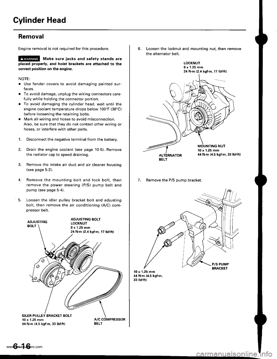
Remove the mounting bolt and lock bolt, then
remove the power steering (P/S) pump belt and
pump (see page 5-4).
Loosen the idler pulley bracket bolt and adjusting
bolt, then remove the air conditioning (A,/C) com,
pressor belt.
ADJUSTINGBOLT
ADJUSTING BOLTLOCKNUT8 x 1.25 mm24 N m {2.4 ksf.m, 17 lbttt}
IOLER PULLEY BBACKET BOLT10 x 1.25 mm44 N.m {4.5 kgtm, 33 lbf ft)
tt aAo-Io
6. Loosen the locknut and mounting nut, then remove
the alternator belt.
LOCKNUT8 x 1.25 mm24 N.m (2.4 kgf.m, 17 lbt.ftl
10 x 1.25 mm44 N.m (4.5 kgt.m. 33 lbf.ft)
7. Remove the P/S OUmo bracket.
l0 x 1.25 mm44 N.m (4.5 kgf.m,33 rbf.ft)
BELT
www.emanualpro.com
Page 130 of 1395
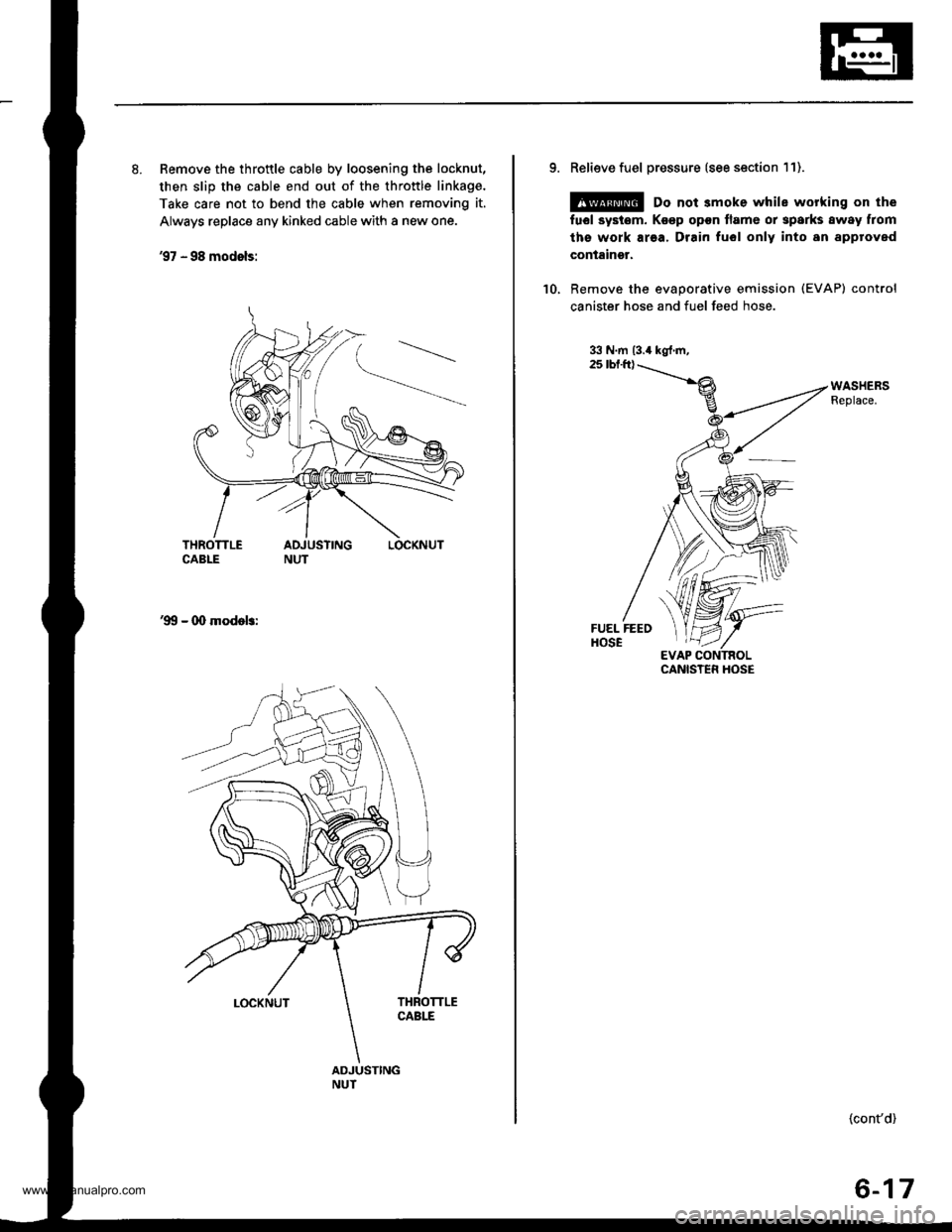
8. Remove the throttle cable by loosening the locknut,
then slip the cable end out of the throttle linkage.
Take care not to bend the cable when removing it.
Always replace any kinked cable with a new one.
'97 - 98 modols:
'!X, - 00 modob:
9. Relieve fuel pressure (see section 11).
@ Do not smoke while working on the
fuel systom. Ko€p opon flame or sparks away from
ths work area. Drain fuol only into an approved
containgr.
'10, Remove the evaporative emission (EVAP) control
canister hose and fuel feed hose.
CANISTER HOSE
{cont'd)
6-17
www.emanualpro.com
Page 131 of 1395
Gylinder Head
Removal (cont'dl
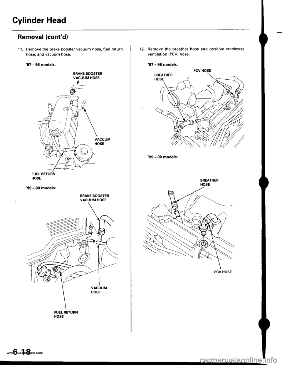
'11. Remove the brake booster vacuum hose. fuel return
hose, and vacuum hose.
'97 - 98 modsls:
VACUUMHOSE
BRAKE BOOSTEBVACUUM HOSE
6-18
BRAKE BOOSTER
12. Remove the breather hose and oositive crankcase
ventilation (PCV) hose,
'97 - 98 models:
BREATHEBHOSE
PCV HOSE
'99 - 00 models:
BREATHERHOSE
PCV HOSE
www.emanualpro.com
Page 132 of 1395

13. Remove the upper radiator hose, heater hose and
water bypass hose.
WATER BYPASS
UPPEBRADIATORHOSE
17
HEATERHOSE
Remove the engine wire harness connectors and
wire harness clamps from the cylinder head and the
intake manifold.
o Four fuel injector connectors
. Engine coolant temperature (ECT) sensor con-
neclor
. Radiator fan switch connector
. Coolant temperature gauge sendlng unlt connec-
tor
. Throttle position sensor connector
. Manifold absolute pressure {MAP) sensor con-
nector
Primary heated oxygen sensor (primary HO2S)
connector
ldle air control (lAC) valve connector
Distributor connector
Remove the spark plug caps and distributor from the
cylinder head.
Remove the cruise control actuator (see section 4).
Support the engine with a jack, then remove the
upper bracket. Make sure to place a cushion
between the oil pan and the iack (see page 6-10).
a
18. Remove the cylinder head cover.
19. Inspect the timing belt (see page 6-9).
CYLINDER
(cont'd)
6-19
www.emanualpro.com
Page 134 of 1395
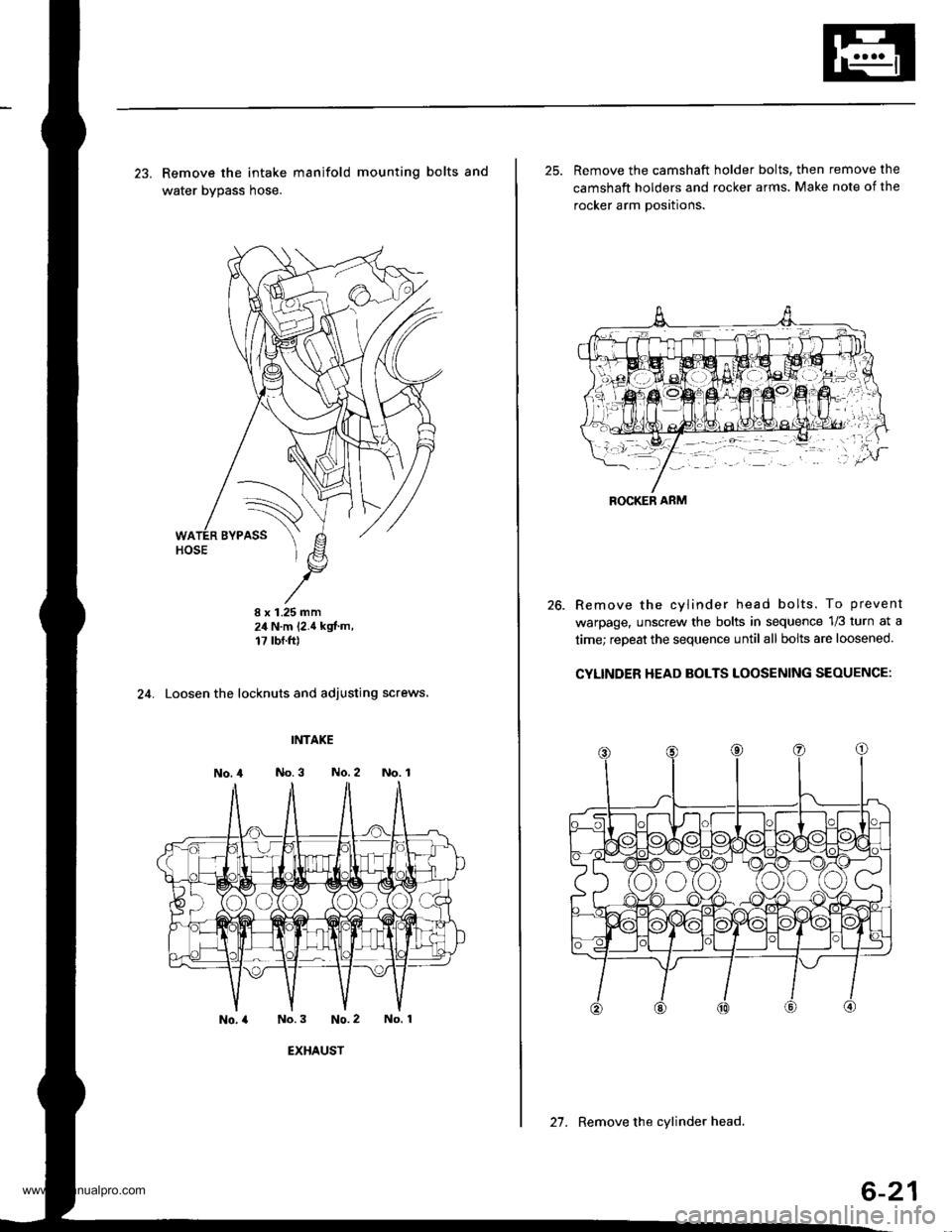
23. Remove the intake manifold mounting bolts and
water bvDass hose.
8 x 1.25 mm2,1 N.m 12.4 kgt.m,17 tbf.ft)
24. Loosen the locknuts and adjusting screws,
INTAKE
No.3 No.2 No. 1
No.3 No.2 No. 1
EXHAUST
No. 4
27. Remove the cylinder head.
6-21
25. Remove the camshaft holder bolts, then remove the
camshaft holders and rocker arms. Make note of the
rocker arm Dositions.
26. Remove the cylinder head bolts. To prevent
warpage, unscrew the bolts in sequence 1/3 turn at a
time; repeat the sequence until all bolts are loosened.
CYLINDER HEAD BOLTS LOOSENING SEOUENCE:
ROCKER ARM
www.emanualpro.com
Page 146 of 1395
21.
22.
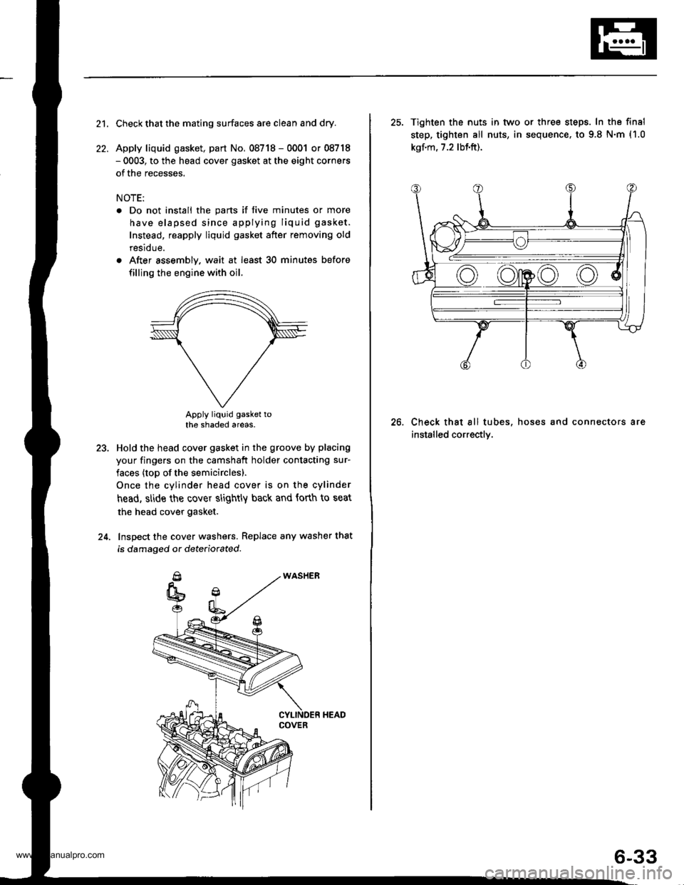
Check that the mating surfaces are clean and dry.
Apply liquid gasket, part No. 08718 - 0001 or 08718- 0003, to the head cover gasket at the eight corners
of the recesses.
NOTE:
. Do not install the parts if five minutes or more
have elapsed since applying liquid gasket.
Instead, reapply liquid gasket after removing old
residue.
. After assembly. wait at least 30 minutes before
filling the engine with oil.
Apply liquid gasket tothe shaded areas.
Hold the head cover gasket in the groove by placing
your fingers on the camshaft holder contacting sur-
faces (top of the semicirclesl.
Once the cylinder head cover is on the cylinder
head, slide the cover slightly back and forth to seat
the head cover gasket.
Inspect the cover washers. Replace any washer that
is damaged or dete(iorated.
23.
24.
25. Tighten the nuts in tvvo or three steps. In the final
step, tighten all nuts, in sequence. to 9.8 N.m (1.0
kgf.m, 7.2 lbf.ft).
Check that all tubes, hoses and connectors are
installed correctly.
26.
6-33
www.emanualpro.com
Page 166 of 1395
PistonsCrankshaft
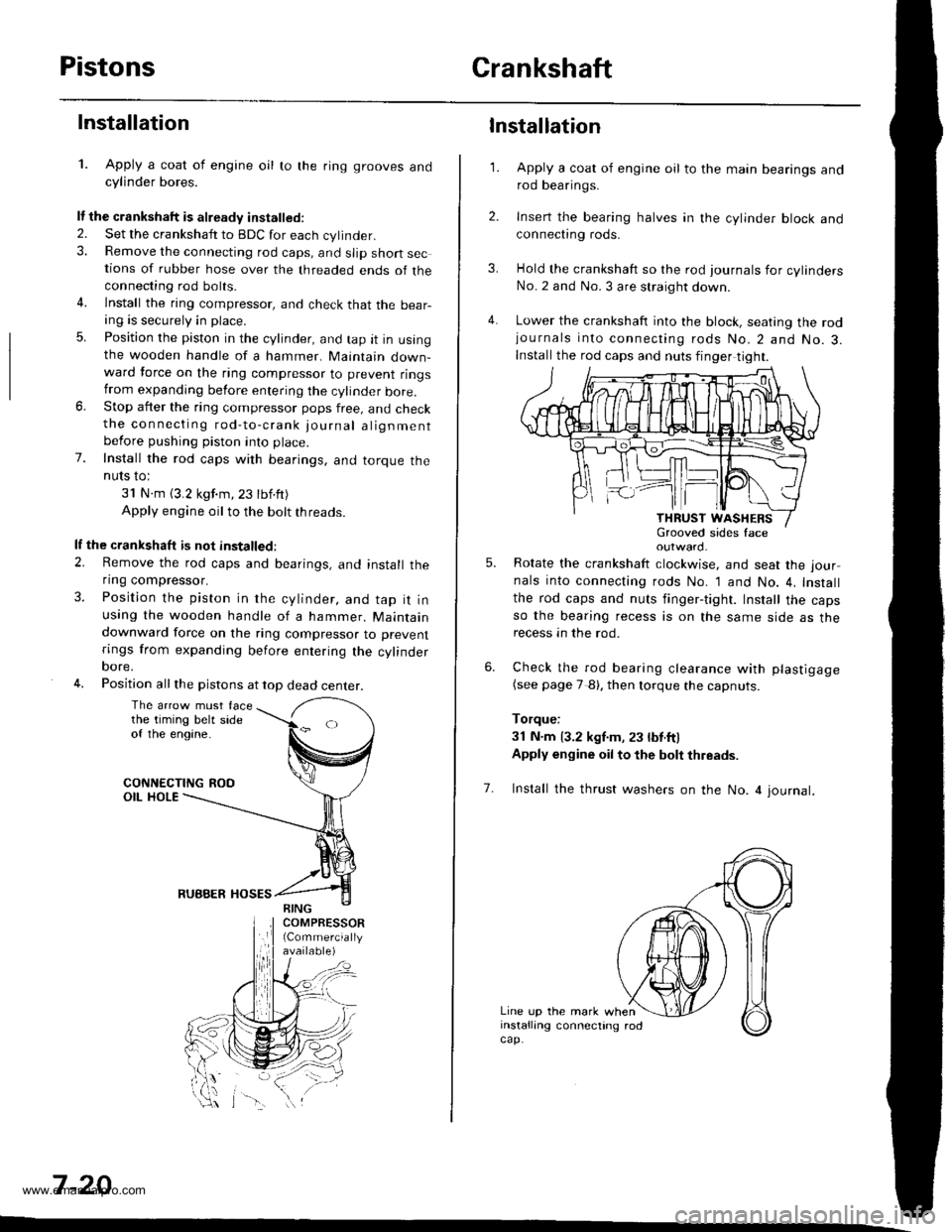
Installation
1. Apply a coat of engine oil to the ring grooves andcylinder bores.
It the crankshaft is already installed.
2. Set the crankshatt to BDC for each cylinder.3. Remove the connecting rod caps, and slip short sections of rubber hose over the threaded ends of theconnecting rod bolts.
4. lnstall the ring compressor, and check that the bear-ang is securely in place.
5. Position the piston in the cylinder, and tap it in usingthe wooden handle of a hammer. Maintain down-ward force on the ring compressor to prevent ringstrom expanding before entering the cylinder bore.6. Stop after the ring compressor pops free, and checkthe connecting rod-to-crank journal alignmentbefore pushing piston into place.
7. Install the rod caps with bearings, and torque theNUIS IO:
31 N.m (3.2 kgf.m,23 tbf.ft)
Apply engine oil to the bolt threads.
lf the crankshaft is not installed:
2. Remove the rod caps and bearings, and install theflng compressor.
3. Position the piston in the cylinder, and tap it inusing the wooden handle of a hammer. Maintaindownward force on the ring compressor to prevent
rings from expanding before entering the cylinderoore,
4. Position all the pistons at top dead center.
The arrow must facethe timing belt sideof the engine.
CONNECTING ROOOIL HOLE
RUBBER HOSES
7 -20
\-\
3.
4.
1.
6.
Installation
Apply a coat of engine oil to the main bearings androd bearings.
Insert the bearing halves in the cylinder block andconnect|ng rods.
Hold the crankshaft so the rod journals for cylindersNo.2 and No. 3 are straight down.
Lower the crankshaft into the block, seating the rodjournals into connecting rods No.2 and No.3.Install the rod caps and nuts finger tight.
outward.
Rotate the crankshaft clockwise, and seat the jour
nals into connecting rods No. 1 and No. 4, Install
the rod caps and nuts finger-tight. Install the capsso the bearing recess is on the same side as therecess an the rod.
Check the rod bearing clearance with plastigage(see page 7 8). then lorque the capnuts.
Torque:
3l N.m 13.2 kgf.m, 23 lbt.ftl
Apply engine oil to the bolt thleads.
5.
7. Install the thrust washers on the No. 4 journal.
Line up the mark wheninstalling connecting rodcap.
www.emanualpro.com