Range switch HONDA CR-V 2000 RD1-RD3 / 1.G User Guide
[x] Cancel search | Manufacturer: HONDA, Model Year: 2000, Model line: CR-V, Model: HONDA CR-V 2000 RD1-RD3 / 1.GPages: 1395, PDF Size: 35.62 MB
Page 410 of 1395
Emission Control System
Evaporative Emission (EVAP) Controls (cont'd)
99 - 00 models:
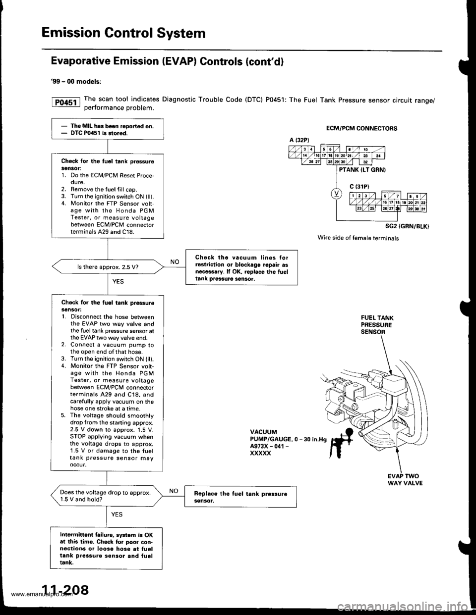
The scan tool indicates Diagnostic Trouble Code {DTC) P0451: The Fuel Tank Pressure sensor circuit range/oerformance Droblem.
ECM/PCM CONNECTORS
SG2 {GRN/BLK)
Wire side of {emaleterminals
FUEL TANKPRESSURESENSOR
VACUUMPUMP/GAUGE.0 -30 in.H9A973X - 041 -
XXXXX
- The MIL har been rooort€d on.- DTC P0451 b storod.
Check lor th6 tu6l tank pr€ssurelen30r:1. Do the ECM/PCM Reset Proce,oure.2. Remove the fuelfill cap.3. Turn the ignition switch ON (ll).4. Monitor the FTP Sensor voltage with the Honda PGMTester, or measure voltagebetween ECM/PCM connectorterminals A29 and C18.
Chock tho vacuum lin6s torrGlriction o. blockago repair asnecessary. lf OK, roplace the fueltank Drer3ur€ sentor.
ls there approx. 2.5 V?
Check for the fuel tank piessureSensot:L Disconnect the hose betweenthe EVAP two way valve andthe fuel tank pressure sensor atthe EVAP two way valve end.2. Connect a vacuum pump tothe open end ofthat hose.3. Turn the ignition switch ON (lll.4. Monitor the FTP S€nsor volt-age with the Honda PGMTester, or measure voltagebetween ECNI/PCNI connectorterminals A29 and C18, andcarefully appiy vacuum on thehose one stroke at a time.5. The voltage should smoothlydrop from the staning approx.2.5 V down to approx. 1.5 V.STOP applying vacuum whenthe voltage drops to approx.1.5 V or damage to the tueltank pressure sensor may
Does the voltage drop to approx.1.5 V and hold?
Intermittent tailuro. sv3tem is OKat this tim€. Chack to. poor con-n€ction6 or 10036 hose at fu6ltank pres3ure ionsor and fueltrnk.
a t32Pl
PTANK ILT GRNI
WAY VALVE
11-208
www.emanualpro.com
Page 519 of 1395

Description
General Operation
The Automatic transmission is a 3-element torque converter and triple-shaft electronically controlled unit which provides 4
speeds forward and 1 reverse speed The unit is positioned in line with the engine'
There are two tvoes of automatic transmission on CR-V; the four-wheel drive (4WD) model ('97 - 00)' and the front-wheel
drive (2WD) model ('98 - 00).
Toroue Converter, G€ars, and Clutches
The torque converter consists of a pump. turbine. and stator assembly in a single unit. The torque converter is connected to
the engine crankshatt. These parts turn together as a unit as the engine turns. Around the outside of the torque converter is
a ring gear which meshes with the starter pinion when the engine is started. The torque converter assembly serves as a fly-
wheel while transmitting power to the transmission mainshaft.
The transmission has three parallel shafts: the mainshaft. the countershaft, and the sub-shaft. The mainshaft is in line with
the engine crankshaft. The mainshaft includes the 1st, 2nd. and 4th clutches, and gears lor 3rd,2nd,4th. reverse and 1st
(3rd gear is integral with the mainshaft, while reverse gear is integral with the 4th gear). The countershaft includes the 3rd
clutch and gears for 3rd,2nd, 4th, reverse, 1st, and park. Reverse and 4th gears can be locked to the countershaft at its cen-
ter, providing 4th gear or reverse, depending on which way the selector is moved. The sub-shaft includes the lst-hold
clutch and gears for lst and 4th.
The gears on the mainshaft are in constant mesh with those on the countershaft and sub-shaft. When certain combinations
of gears are engaged by the ctutches, power is transmitted from the mainshaft to the countershaft to provide E, D!, tr, tr,
and E position ('97 - 98 models). and E. E, E, and E position ('99 - 00 models)'
Electlonic Control
The electronic controt system consists of the Powenrain Control Module (PCM), sensors, a linear solenoid, and four
solenoid valves. Shifting and lock-up are electronically controlled for comfortable driving under all conditions. The PCM is
located below the dashboard, under the kick panel on the passenger's side.
Hydraulic Control
The valve bodies include the main valve body, the secondary valve body, the regulator valve body, the servo body, and
the lock up valve body. They are bolted to the torque converter housing. The main valve body contains the manual valve,
the 1-2 shift valve, the 2nd orifice control valve. the CPB {Clutch Pressure Back-up) valve, the modulator valve, the servo
control valve. the relief valve, and ATF pump gears. The secondary valve body contains the 2-3 shift valve, the 3-4 shift
valve, the 3,4 orifice control valve. the 4th exhaust valve and the CPC (Clutch Pressure Control) valve. The regulator valve
bodv contains the pressure regulator valve, the torque converter check valve, the cooler relief valve, and the lock-up con-
trol valve. The servo body contains the servo valve which is integrated with the reverse shift tork, and the accumulators
The lock-up valve body contains the lock-up shift valve and the lock-up timing valve. The linear solenoid and the shift con-
trol solenoid valve Ay'B are bolted to the outside of the transmission housing, and the lock-up control solenoid valve Ay'B is
bolted to the outside of the torque converter housing. Fluid trom the regulator passes through the manual valve to the
various control valves. The clutches receive fluid from their respective feed pipes or internal hydraulic circuit
ShiftControl Mechanism
input from various sensors located throughout the vehicle determines which shift control solenoid valve the PCM will acti-
vate. Activating a shift control solenoid valve changes modulator pressure, causing a shift valve to move. This pressurizes
a line to one of the clutches. engaging that clutch and its corresponding gear. The shift control solenoid valves A and B are
controlled by the PCM.
Lock-up Mechanism
tn E! position (,97 - 98 modets) and in E position ('99 - O0 models), in 3rd and 4th, and in Del position in 3rd ('97 - 98
models) and in El position with Over,Drive (O/D) is OFF (by pressing rhe O/D switchl in 3rd ('99 - 00 models), pressurized
fluid is drained from the back of the torque converter through a fluid passage, causing the lock-up piston to be held
against the torque converter cover, As this takes place, the mainshaft rotates at the same speed as the engine crankshaft.
Together with hydraulic control, the PcM optimizes the timing of the lock-up mechanism The lock-up valves control the
range of lock-up according to lock-up control solenoid valves A and B, and the linear solenoid. When lock-up control
solenoid valves A and B activate, the modulator pressure changes. The lock-up control solenoid valves A and B and the
linear solenoid are controlled by the PCM.
{cont'd)
14-3
www.emanualpro.com
Page 520 of 1395
Description
General Operation (cont'dl
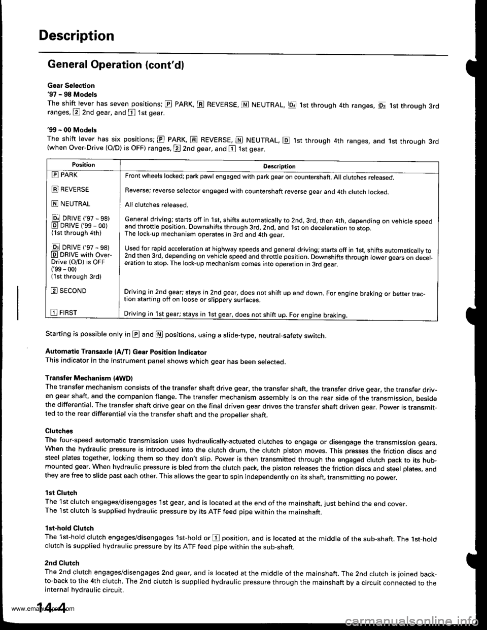
Gsar Selection'97 - 98 Models
The shift lever has seven positions; El PARK, ts REVERSE, N NEUTRAL, Ell 1st through 4th ranges, lpq 1st th.ough 3rdranges, P 2nd gear, and [ 1st gear
'99 - 00 Models
The shitt lever has six positions; El PARK, E REVERSE, E NEUTRAL. E ,lst through 4th ranges, and 1st through 3rd(when Over-Drive (O/D) is OFF) ranges. @ 2nd gear, and E 1st gear.
Starting is possible only in @ and @ positions. using a slide-type. neutral-safety switch.
Automatic Transaxle (A/T) Gear Position IndicatorThis indicator in the instrument panel shows which gear has been selected.
Transler Mochanism {4WD}
The transfer mechanism consists of the transfer shaft drive gear. the transfer shaft. the transfer drive gear, the transfer driv-en gear shaft, and the companion flange, The transfer mechanism assembly is on the rear side ot the transmission. besidethe differential. The transfer shaft drive gear on the final driven gear drives the transfer shaft driven qear. power is transmit-ted to the rear differential via the transfer shaft and the Drooeller shaft.
Clutches
The four-speed automatic transmission uses hydraulically-actuated clutches to engage or disengage the transmission gears.When the hydraulic pressure is introduced into the clutch drum, the clutch piston moves. This presses the friction discs andsteel plates together, locking them so they don't slip. Power is then transmifted through the engaged clutch pack to its hu$mounted gear. When hydraulic pressure is bled from the clutch pack, the piston releases the friction discs and steel plates, andthey are free to slide past each other. This allows the gearto spin independently on its shaft, transmitting no power.
lst Clutch
The 1st clutch engages/disengages lst gear, and is located at the end ofthe mainshaft, just behind the end cover.The 1st clutch is supplied hydraulic pressure by its ATF feed pipe within the mainshaft.
lst-hold Clutch
The 1st-hold clutch engages/disengages 1st-hold or E position, and is located at the middle of the sub-shaft. The 1st-holdclutch is supplied hydraulic pressure by its ATF feed pipe within the sub-shaft.
2nd Clutch
The znd ciutch engages/disengages 2nd gear, and is located at the middle of the mainshaft. The 2nd clutch is joined back-to-back to the 4th clutch. The 2nd clutch is supplied hydraulic pressure through the mainshaft by a circuit connected to theinternal hydraulic circuit.
PositionDescription
Reverse; reverse selector engaged with countershaft reverse gear and 4th clutch locked.
Allclutches released.
General driving; starts off in 1st, shifts automatically to 2nd, 3rd, then 4th, depending on vehicle speedand throftle position. Downshifts through 3rd,2nd, and lst on deceleration to stop.The lock-up mechanism operates;n 3rd and 4th gear.
used for rapid €cceleration at highway speeds and general driving; stans off in 1st, shifts automatically to2nd_then 3rd, dejending on vehicle speed and throttle position. Downshifts through lower gears on decel-eration to stop. The lock-up mechanism comes into operation in 3rd gear.
Driving in 2nd_gear; stays in 2nd gear, does not shift up and down. For engine braking or better trac_tion starting off on loose or slippery surfaces.
Driving in 1st gear; stays in 1st gear, does not shift up. For engine braking.
tll PARK
t!!l l|EvEn>E
E NEUTRAL
Ell DRrvE ('97 - sB)E DRrvE ('ss - oo)(1st through 4th )
E DRrvE {'97 - s8)O DRTVE with over-Drive (O/D) is OFF('99 - 00)(1st through 3rd)
E SECOND
E FIRST
14-4
www.emanualpro.com
Page 555 of 1395
Lock-up System
TOROUE CONVERTER
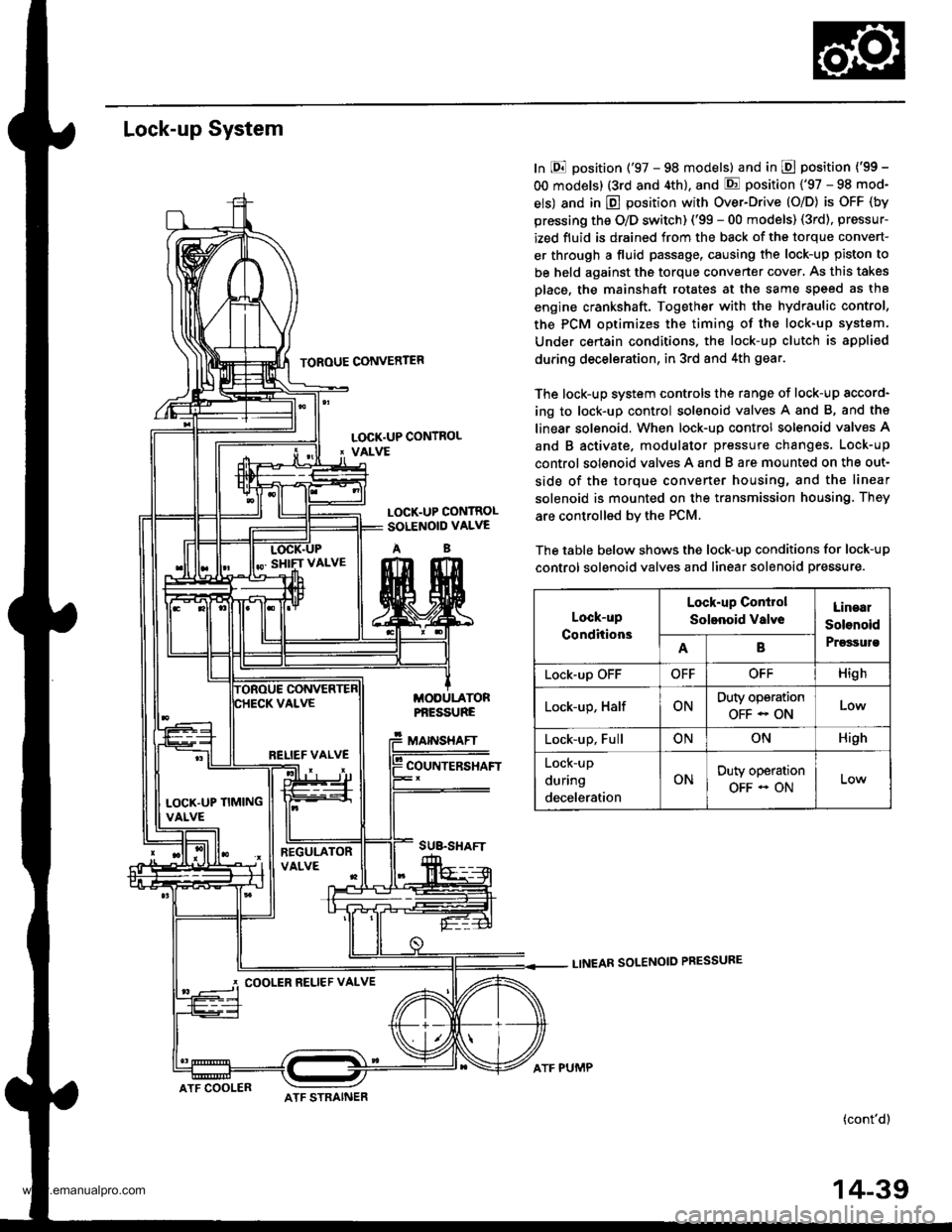
In E position ('97 - 98 models) and in E position ('99 -
OO models) (3rd and 4th), and E position ('97 - 98 mod-
els) and in E position with Over-Drive (O/D) is OFF (by
pressing the O/D switch) ('99 - 00 models) (3rd), pressur-
ized fluid is drained from the back of the torque convert-
er through a fluid passage, causing the lock-up piston to
be held against the torque converter cover, As this takes
Dlace, the mainshaft rotates at the same speed as th8
engine crankshaft. Together with the hydraulic control,
the PCM optimizes the timing of the lock-up system.
Under certain condltions. the lock-up clutch is appli€d
during deceleration, in 3rd and 4th gear.
The lock-up system controls the range of lock-up sccord-
ing to lock-up control solenoid valves A and B, and ths
linear solenoid. When lock-up control solenoid valves A
and B activate. modulator pressure changes. Lock-up
control solenoid valves A and B are mounted on the out-
side of the torque converter housing, and the linear
solenoid is mounted on the transmission housing. They
are controlled bv the PCM.
The table below shows the lock-up conditions for lock-up
control solenoid valves and linear solenoid pressure.
LINEAR SOLENOID PRESSURE
(cont'd)
LOCK.UP CONTROL' VALVE
LOCK.UP CONTROLSOLENOID VALVE
AB
MODULATORPf,ESSURE
MAINSHAFT
COUNTERSHAFT
SUB.SHAFT
Lock-up
Conditions
Lock-up Conirol
Solenoid valveLinaal
Solenoid
PrgssulsAB
Lock-up OFFOFFOFFHigh
Lock-up, HalfONDuty operation
OFF - ONLow
Lock-up, FullONONHigh
Lock-up
during
deceleration
ONDuty operation
OFF - ON
RELIEF VALVE
LOCK'UP TIMINGVALVE
COOLER RELIEF VALVE
ATF COOLERATF STRAINER
ATF PUMP
14-39
www.emanualpro.com
Page 957 of 1395
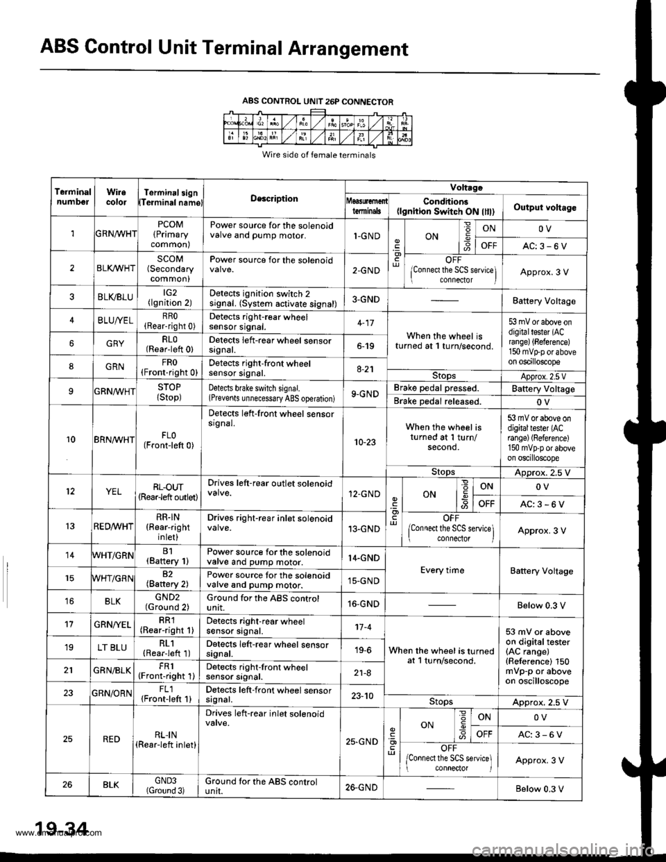
ABS Control Unit Terminal Arrangement
ABS CONTROL UNIT 26P CONNECTOR
Wire side of female terminals
TeiminalnumbelWiiecolorTerminal3ignTeiminalnamglDescription
Voltrge
tdminalsCondhions(lgnition Switch ON llll)Output voltago
1GRNn/VHTPCOM(Primary
common)
Power source for the solenoidvalve and pump motor.1-GNDON6
ONOV
OFFAC:3-6V
2BLI(WHTSCOM(Secondary
common)
Power source for the solenoid2-GNDOFF
lConnect the SCS seNice] connector IApprox.3 V
BLVBLU(lgnition 2)Detects ignition switch 2signal. (System activate signal)3-GNDBattery Voltage
4BLUA/ELRRO(Rear-right 0)Detocts right-rear wheelsensor srgnat.When the wheel isturned at 1 turn/second.
53 mV or above ondigitaltester (ACrange) {Beference)150 mvtrp or aboveon oscilloscope
GRYRLO(Rear-left 0)Detects left-rear wheel sensorsrgnat.6-19
8GRNFRO(Fronr-right 0)Detects right-front wheelsensor signal.8-21StopsApprox.2.5 VSTOP
{Stop)Detects bfake switch signal.(Prevents unnecessary ABS operation)9-GNDBrake pedal pressed.Battery Voltage
Brake Dedal released.OV
10BRN^/VHTFLO(Front-left 0)
Detects left-front wheel sensorsrgnal.
10-23
When the wheel isturned at 1 turn/second.
53 mV or above ondigitaltester lACrange) (Reference)
150 mvpp or aboveon oscilloscope
StopsADprox. 2.5 V
YELRL-oUT(Rearleft outlet)
Drives left-rear outlet solenoid12.GNDONONOV
OFFAC:3-6V
13RED^/vHTRR.IN(Rear-right
inlet)
Drives right-rear inlet solenoid13.GNDOFF
lConnect the SCS service\ connector IApprox. 3 V
14WHT/GRNB1(Baftery 1)Power source for the solenoidvalve and pump motor.14.GND
Every timeBattery Voltage82(Battery 2)Power source for the solenoidvalve and pump motor.15-GND
16BLKGND2(Ground 2)Ground for the ABS controlunit.16-GNDBelow 0.3 V
't7GRN/YELRR1(Rear-right 1)Detects right-rear wheelsensor signal.'t7 -4
When the wheel is turnedat l turn/second,
53 mV or aboveon digitaltester(AC range)(Reference) 150mVp-p or aboveon oscilloscope
19LT BLURL1(Rearieft 1)Detects left-rear wheel sensorsignal.19-6
GRN/BLKFR1(Front-right 1)Detects right-front wheelsensor srgnat.21-8
23GBN/ORNFL1{Front-left 1}Detects left-front wheel sensorsagnal.23-10StopsApprox. 2.5 V
REDRLI N(Rear-left inlet)
Drives left-rear inlet solenoid
25,GND
ON
=
-9ONOV
AC:3-6V
OFF
/Connect the SCS service] conneclor IApprox. 3 V
26BLKGND3(Gtound 3)Ground tor the ABS controluntI.26-GNDBelow 0.3 V
19-34
www.emanualpro.com
Page 1316 of 1395
Precautions/Procedures
)General Precautions
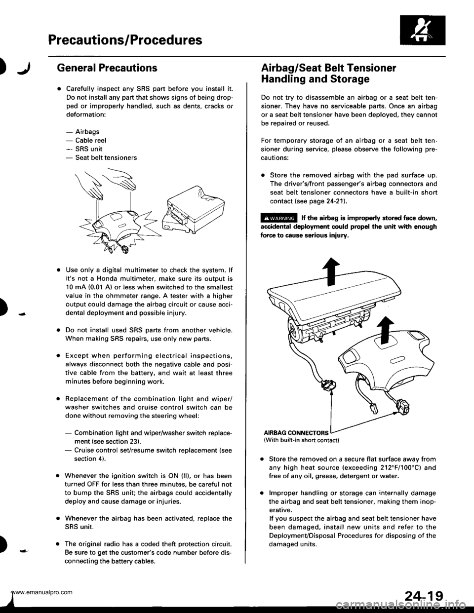
Carefully inspect any SRS part before you install it.
Do not install any part that shows signs of being drop-
ped or improperly handled, such as dents, cracks or
deformation:
- Airbags- Cable reel- SRS unit- Seat belt tensioners
N
)-
Use only a digital multimeter to check the system, lf
it's not a Honda multimeter, make sure its output is
10 mA (0,01 A) or less when switched to the smallest
value in the ohmmeter range. A tester with a higher
output could damage the airbag circuit or cause acci-
dental deployment and possible injury.
Do not install used SRS Dans from another vehicle,
When making SRS repairs, use only new pans.
Except when performing electrical inspections,
always disconnect both the negative cable and posi-
tive cable from the batterv. and wait at least three
minutes before beginning work.
Replacement of the combination light and wiper/
washer switches and cruise control switch can be
done without removing the steering wheel:
- Combination light and wiper/washer switch replace-
ment {see section 231.- Cruise control sevresume switch replacement (see
section 41.
Whenever the ignition switch is ON {ll}, or has been
turned OFF for less than three minutes, be careful not
to bump the SRS unit; the airbags could accidentally
deploy and cause damage or injuries.
Whenever the airbag has been activated, replace the
SRS unit.
The original radio has a coded theft protection circuit.
Be sure to get the customer's code number before dis-
connecting the battery cables.
)
Airbag/Seat Belt Tensioner
Handling and Storage
Do not try to disassemble an airbag or a seat belt ten-
sioner. They have no serviceable parts. Once an airbag
or a seat belt tensioner have been deployed. they cannot
be repaired or reused.
For temporary storage of an airbag or a seat belt ten-
sioner during service, please observe the following pre-
cautons:
. Store the removed airbag with the pad surface up.
The driver's/front passenger's airbag connectors and
seat belt tensioner connectors have a built-in short
contact (see page 24-211.
@ r th€ airb.g is impropcrty stor€d face down,
accidental deployment could propel the unit with enough
forc€ to caus6 serious iniury,
Store the removed on a secure flat surface awav from
any high heat source (exceeding 212"F/100'C) and
free of any oil, grease. detergent or water.
lmproper handling or storage can internally damage
the airbag and seat belt tensioner. making them inop-
erative.
lf you suspect the airbag and seat belt tensioner have
been damaged, install new units and refer to the
Deploymenvoisposal Procedures for disposing of the
damaoed units.
AIRBAG CONNECTORS
www.emanualpro.com
Page 1323 of 1395
Troubleshooting
Self-diagnostic Procedures
The self-diagnostic function of the SRS system allows it to locate the causes of system problems and to store this informa-
tion in memory, For easier troubleshooting, this data can be retrieved via a data link circuit.
. When you turn the ignition switch ON (ll). the SRS indicator will come on. lf it goes off after six seconds, the system is
normal.
. lf there is 8n abnormality, the system locates and defines the problem. stores this information in memory, and turns
the SRS indicator light on. The data will remain in the memory even when the ignition switch is turned off or if the bat-
terv is disconnected.
. When you connect the SCS service connector to the service check connector (2P), and turn the ignition switch ON (ll),
the SRS indicator light will indicate the diagnostic trouble code (DTC) by the number of blinks.
. After reading and recording the DTC, proceed with the troubleshooting forthis code.
Precsutions
. Use only a digital multimeter to check the system. lf it's not a Honda multimeter. make sure its output is 10 mA (0.01 A)
or less when switched to the smallest value in the ohmmeter range. A tester with a higher output could damage the
airbag circuit or cause accidental airbag deployment and possible injury.
. Whenever the ignition switch isON (ll). or has been turned OFF for less than three minutes, be careful nottobumpthe
SRS unit; the airbags could accidentally deploy and cause damage or injuries.
. Before you remove the SRS main harness, disconnect the airbag and tensioner connectors (see page 24-23).
. Make sure the battery is sufficiently charged (see section 23). lf the battery is dead or low, measuring values won't be
correct.
. Do not touch a tester probe to the terminals in the SRS unit or harness connectors, and do not connect the terminals
with a jumper wire. Use only the backprobe set and the SCS service connector.
For backprobing spring-loaded lock type con nectors, .efet to page 24-22.
Reading the DTC
When the SRS indicator light is on, read the DTC using one of these methods;
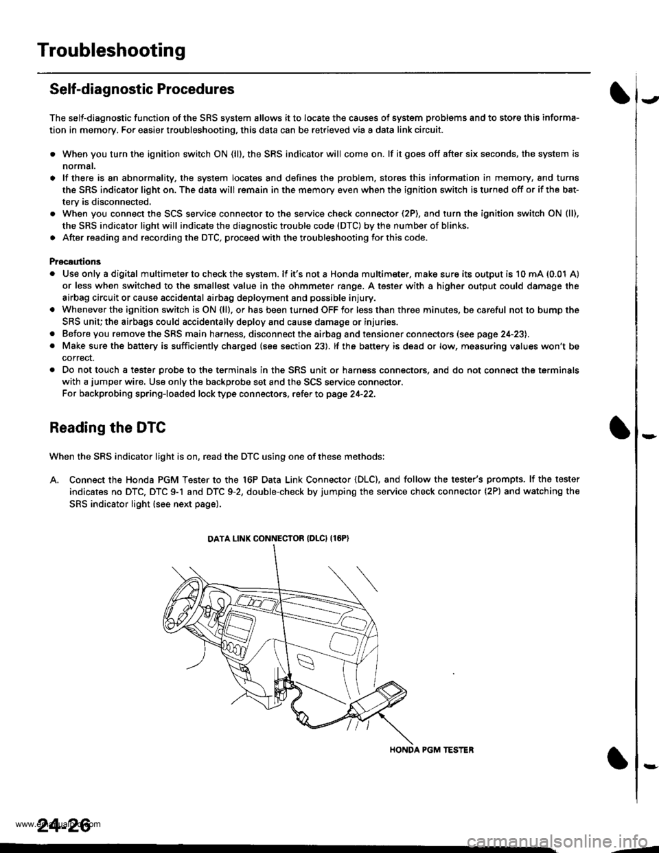
A. Connect the Honda PGM Tester to the 16P Data Link Connector {DLC), and follow the tester's prompts. lf the tester
indicates no DTC, DTC 9-1 and DTC 9-2, double-check by jumping the service check connector (2P) and watching the
SRS indicator light (see next page).
HONDA PGM TESTER
DATA LINK CONNECIOR {DLCI {16P)
24-26
,1
www.emanualpro.com