cata HONDA CR-V 2000 RD1-RD3 / 1.G User Guide
[x] Cancel search | Manufacturer: HONDA, Model Year: 2000, Model line: CR-V, Model: HONDA CR-V 2000 RD1-RD3 / 1.GPages: 1395, PDF Size: 35.62 MB
Page 278 of 1395
Troubleshooting
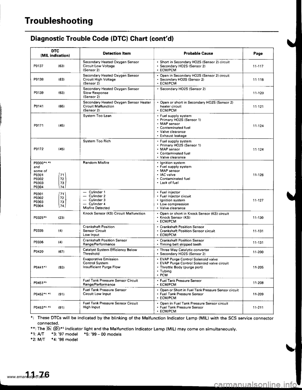
Diagnostic Trouble Code (DTCI Chart (cont'd)
*: These DTCS will be indicated by the blinking o{ the Malfunction Indicator Lamp (MlL) with the SCS service connector
connected.**: The E (El*s indicator light and the Malfunction Indicator Lamp {MlL) may come on simultaneously,*1; A/T *3: '97 model *5: '99 - 00 models*2: MlT *4: '98 model
11-76
DTClMlL indicationlDetection hemProbable Caus.Page
P0137(63)Secondary Heated Oxygen SensorCircuit Low Voltage{Sensor 2)
Shon in Secondary HO2S (Sensor 2) circuatSecondary HO2S (Sensor 2)ECM/PCM
'n-1t7
P0138 (63)Secondary Heated Oxygen SensorCircuit High VoltageOpen in Secondary HO2S (Sensor 2) circuitSecondary HO2S (Sensor 2)EC|\il/PCM11118
P0139{63)Secondary Heated Oxygen Sensor
lSensor 2i
Secondary HO2S (Sensor 2)11-120
P0141 (65)Second6ry Heated Oxygen Sensor HeaterCircuit Malfunction(Sensor 2)
Open orshon in Secondary HO2S (Sensor 2)heater circuitEC|V/PCtu11't2l
P0r71 (45)
System Too LeanFuel supply systemPrimary HOzS (Sensor 1)
Contaminated fuel
Exhaust leakage
11124
P0112 (45)
System Too RichFuel supplv systemPrimary HO2S (Sensor 1)
Contaminated fuel11 124
and
Po3ol ltr \P0302 112 |P0303 173 iP0304 \74 t
Random Mistirelgnition systemFuel supply system
IAC valveContaminated fuelLack of fuel
11-126
P0301 /71 \P0302 112 |P0303 173 |P0304 \7 4l
- Cylinder 1- Cylinder 2Cylinder 3- Cylinder 4Misfire Detected
Fuel injectorFuel injector circuitlgnition system't't 127
P0325*5{23)Knock Sensor {KS) Circuit MalfunctionOpen or shon in Knock Sensor (KS) circuitKnock Sensor (KS)ECM/PCt\411-130
P033s{4}Crankshaft PositionSensor CircuitCrankshaft Position SensorCrankshaft Positaon Sensor circuitE Cl\,l/PC l\,'!11-131
P0336(4)Crankshaft Position SensorRange/PerformanceCrankshaft Position SensorTiming belt skipped teeth11,131
P0420{67)Catalyst System Efficiency BelowThresholdThree Way Catalytic convenerSecondary HO2S {Sensor 2)'t1-200
P0441*3 (92)
Evaporative EmissionControlSystemInsulficient Purge Flow
EVAP Purge Control Solenoid valveEVAP Purge Control Solenoid valve circuitThrottle gody (purge port)TubingPCM
'It 205
P0451*5FuelTank Pressure Sensor CircuitBange/PerformanceFuel Tank Pressure SensorECM/PCMt't-208
(91iFuel Tank Pressure SensorCirclit Low InputOpsn orShort in FuelTank Pressure Sensor circuitFuel Tank Pressure SensorECM/PCt\411-209
P0453*r.5 {91)FuelTank Pressure Sensor CircuitHigh InputOpen in Fuel Tank Pressure Sensor circuitFuel Tank Pressure SensorECt /PCt\.111-211
www.emanualpro.com
Page 328 of 1395
PGM-FI System
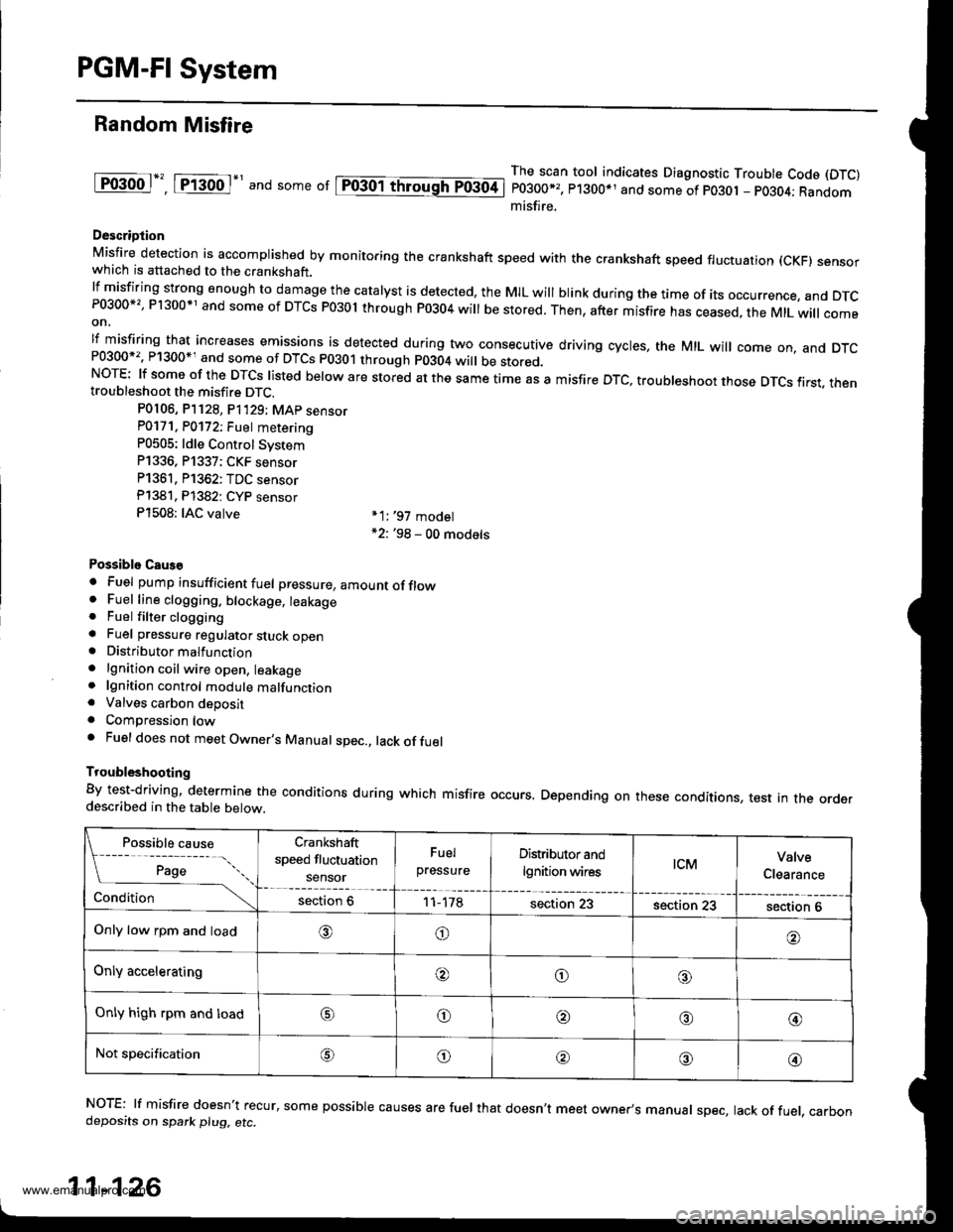
Random Misfire
lF()gool", tftod-' and some or lpiogol throughTo3oti
The scan tool indicates Diagnostic Trouble Code (DTC)
P0300*,, P1300*1 and some of po30t - pO3O4; Randommisfire.
Descriotion
Misfire detection is accomplished by monitoring the crankshaft speed with the crankshaft speed fluctuation (cKF) sensorwhich is attached to the crankshaft.lfmisfiring strong enough to damage the catalyst is detected, the MIL will blink during the time of its occurrence, and DTcP0300*'�, P1300*1 and some of DTCs P03ol through P0304 will be stored. Then, after misfire has ceased, the MtL will comeon,
lf misfiring that increases emissions is detected during two consecutive driving cycles, the MIL will come on, and DTcand some of DTCS p0301 through p0304 wi
be stored.NOTE: lf some of the DTCS listed below are stored at the same time as a misfire DTc, troubleshoot those DTcs first. thentroubleshoot the misfire DTC.
P0106, P]128, P1'129; MAp sensorP0171. P0172; Fuet metering
P0505: ldle Control Svstem
P1336, P1337; CKF sensor
P1361, P1362: TDC sensor
Pl381. Pl382: CYP sensor
P1508: IAC valve *1:,97 model*2: '98 - 00 models
Possiblo Caus€
. Fuel pump insufficient fuel pressure, amountofflow. Fuel line clogging. blockage, leakage. Fuel filter clogginga Fuel pressure regulator stuck open. Distributormalfunction
. lgnition coil wire open, leakage. lgnition control module malfunction. Valves carbon deposita Compression lowa Fuel does not meet Owner's Manual spec., lack offuel
Troubleshooting
By test-driving, determine the conditions during which misfire occurs. Depending on these conditions, test in the orderdescribed in the table below.
Possible cause
[ ;;;;- -....
Crankshaft
speed fluctuation
sensor
Fuel
pressureDistributor and
lgnition wirestcMValve
Clearance
Conditionsection 611-178section 23section 23section 6
Only low rpm and load,6)o
Only acceleratingooo
Only high rpm and loado@,a'@
Not specificationG\o@o@
NOTE: lf misfire doesn't recur, some possible causes are fuel that doesn't meet owner's manual spec, lack of fuel, carbondeposits on spark plu9, etc.
11-126
www.emanualpro.com
Page 329 of 1395
![HONDA CR-V 2000 RD1-RD3 / 1.G User Guide
Misfire Detected in One Cylinder
Ipffi1] Thescantoot indicates Diagnostic Trouble Code (DTC) P0301: Cylinder 1 misfire detected.
lF03O2l 16".""n toot indicates Diagnostic Trouble Code (DTC) P0302; Cy HONDA CR-V 2000 RD1-RD3 / 1.G User Guide
Misfire Detected in One Cylinder
Ipffi1] Thescantoot indicates Diagnostic Trouble Code (DTC) P0301: Cylinder 1 misfire detected.
lF03O2l 16".""n toot indicates Diagnostic Trouble Code (DTC) P0302; Cy](/img/13/5778/w960_5778-328.png)
Misfire Detected in One Cylinder
Ipffi1] Thescantoot indicates Diagnostic Trouble Code (DTC) P0301: Cylinder 1 misfire detected.
lF03O2l 16".""n toot indicates Diagnostic Trouble Code (DTC) P0302; Cylinder 2 misfire detected.
I P0303 | fne scan tool indicates Diagnostic Trouble Code (DTC) P0303: Cylinder3 misfire detected.
lF0il04l 16" ""un tool indicates Diagnostic Trouble Code (DTC) PO3O4: Cylinder 4 misfire detected
Description
Misfire detection is accomplished by monitoring the crankshaft speed with the crankshaft speed fluctuation (CKF) sensor
which is attached to the crankshaft.
lf misiiring strong enough to damage the catalyst is detected, the MIL will blink during the time of its occurrence. and DTC
P0301, P0302, P0303 and/or P0304 will be stored. Then, after the misfire has ceased, the MIL will come on.
lf misfiring that increases emissions is detected during two consecutive driving cycles. the MIL will come on, and DTc
P0301, P0302, P0303 and/or P0304 will be stored.
NOTE: lJ some of the DTcs listed below are stored at the same time as a misfire DTc, troubleshoot those DTcs first, then
troubleshoot the misfire DTC.
P0107, P0108, P'n2a, P1129t MAP sensor
Po'17 'l , P0112t Fuel suPP|Y system
P0441: EVAP insufficient Purge flow
P1336, P1337: CKF sensor
P1359, Pl361, P1362: TDC sensor
Pl381, P1382: CYP sensor
Possible Cause
. Fuel injector clogging, fuel leakage, air leakage
. Fuel injector circuit open or shorted
. Spark plug carbon deposits, fouling, malfunction
. lgnition wires open, leaking
. Distributor malfunction
. Compression low
. Valve clearance out of specification
(cont'd)
11-127
www.emanualpro.com
Page 401 of 1395
Emission Control System
System Description
The emission control system includes, a Three Way
Catalytic Converter {TWC), Positive Crankcase Ventilation
(PCV) svstem and Evaporative Emission (€VAP) Control
system. The emission control system is designed to meet
federal and state emission standards.
Tailpipe Emission
Inspsction
!@ Do not smoke during this procsdura. Keep
any open tlame away from your work area.
1. Start the engine. Hold the engine at 3,000 rpm with
no load (in Park or neutral) until the radiator fan
comes on, then let it idle,
Connect a tachometer.
Check and, if necessary, adjust the idle speed, (see
page 11-169, 170).
Warm up and calibrate the CO meter according to the
meter manufacturer's instructions.
Check idle CO with the headlights, heater blower, rear
window defogger, cooling fan, and air conditioner off.
(Canada) Pull the parking brake lever up. Start the
engine, then check that the headlights are off.
CO meter should indicate 0.1% maximum.
4.
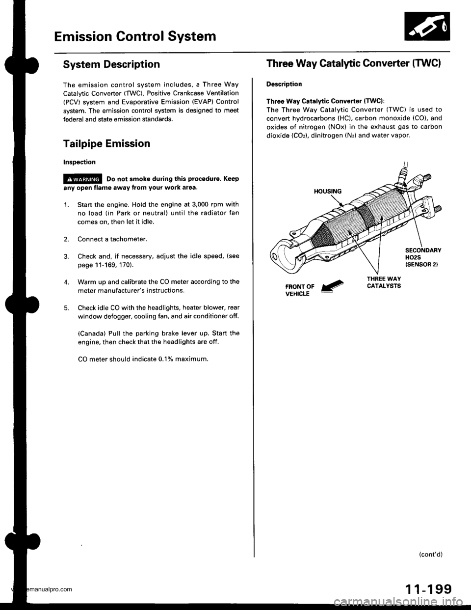
Three Way Catalytic Converter (TWCI
DsscriDtion
Three Way Catalytic Convertsr lTwcl:
The Three wav Catalvtic Converter (TWC) is used to
convert hydrocarbons (HC), carbon monoxide (CO), and
oxides of nitrogen (NOx) in the exhaust gas to carbon
dioxide (COr), dinitrogen (Nr) and water vapor,
{cont'd)
1 1-199
www.emanualpro.com
Page 402 of 1395
Emission Control System
Three Way Catalytic Converter {TWCI (cont'd}
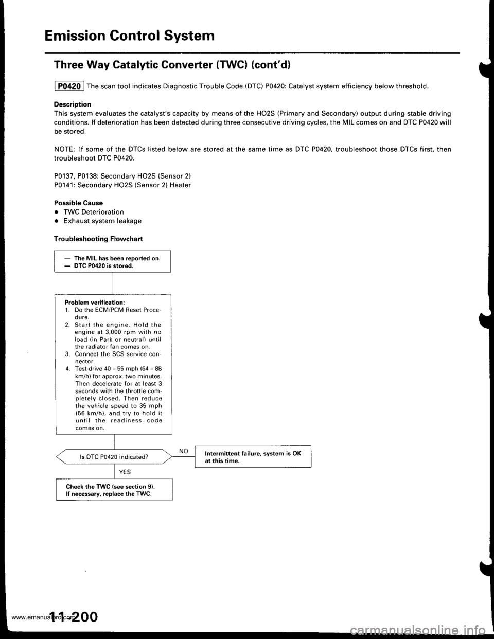
1P0420 Thescantool indicates Diagnostic Trouble Code (DTC) P0420: Catalyst system efficiency belowthreshold.
DescriDtion
This system evaluates the catalyst's capacity by means of the HO2S (Primary and Secondary) output during stable driving
conditions. lf deterioration has been detected during three consecutive driving cycles, the MIL comes on and DTC P0420 will
be stored.
NOTE: lf some of the DTCS listed below are stored at the same time as DTC P0420, troubleshoot those DTCS first. then
troubleshoot DTC P0420.
P0137, P0138: Secondary HO2S (Sensor 2)
P0141: Secondary HO2S (Sensor 2) Heater
Possible Cause
. IWC Deterioration
. Exhaust system leakage
Troubleshooting Flowchart
- The MIL has been reDoried on.- DTC P0420 is stored.
Problem verification:1. Do the ECM/PCM Reset Procedure,2. Start the engine. Hold theengine at 3,000 rpm with noload (in Park or neutrali untilthe radiator fan comes on.3. Connect the SCS service connector.4. Test-drive 40 - 55 mph (64 - 88km/h) for approx. lwo minutes.Then decelerate for at least 3seconds with the throftle completely closed. Then reducethe vehicle speed to 35 mph
156 km/h), and try to hold ituntil the readiness code
Intermittent tailure. system is OKat this time.ls DTC P0420 indicated?
Check the TWC (see section 9).lI nocessary, replace the TwC.
11-200
www.emanualpro.com
Page 594 of 1395
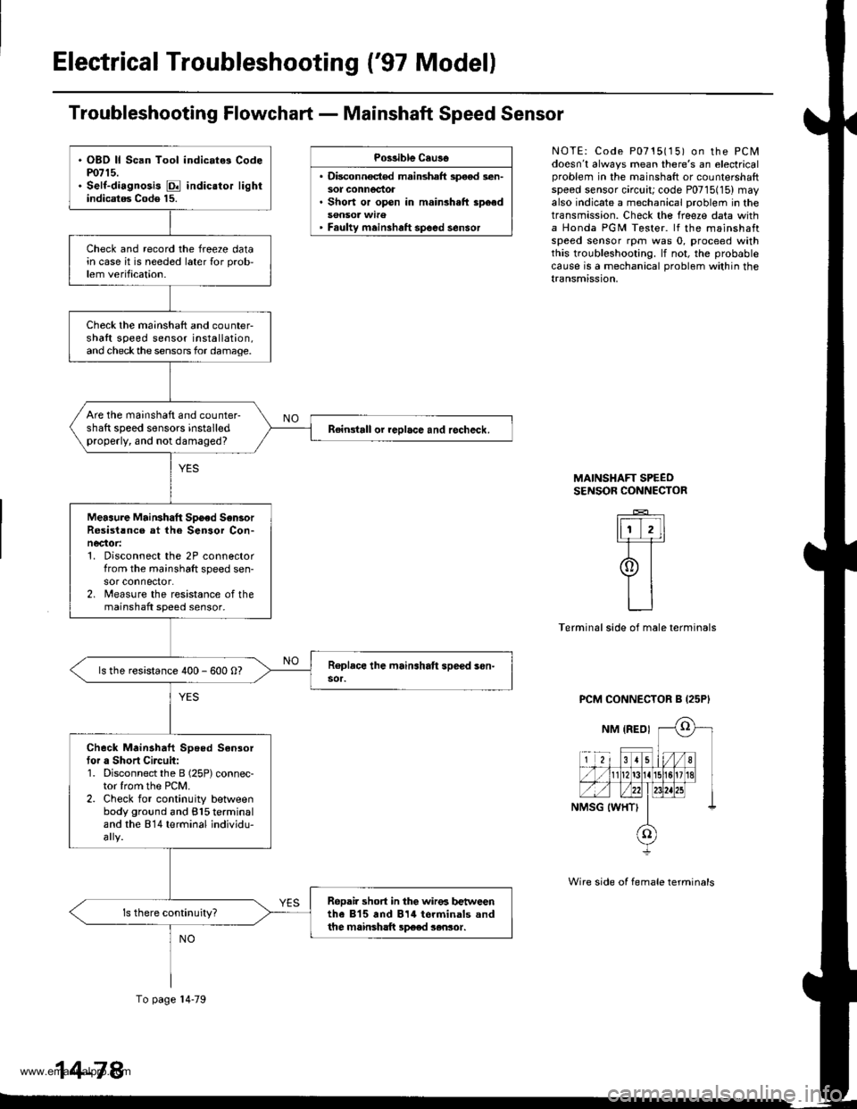
Electrical Troubleshooting {'97 Model)
Troubleshooting Flowchart - Mainshaft Speed Sensor
Po$ible Cau3o
. Disconnocted mainshaft speod sen-sot connectot. Short or open in mainsh.ft sp6ed
' Faulty meinshaft spoed sensor
NOTE: Code P0715115) on the PCMdoesn't always mean there's an electricalproblem in the mainshaft or counlersharlspeed sensor circuit; code P0715(15) mayalso indicate a mechanical problem in thetransmission. Check the freeze data witha Honda PGM Tester. lf the mainshaftspeed sensor rpm was 0, proceed withthis troubleshooting. lf not, the probablecause is a mechanical problom within thetransmission,
MAINSHAFT SPEEOSENSOR CONNECTOR
_E_
ItiT,ll-F=r
9t
LJ
Terminal side of male terminals
PCM CONNECTOR B {25P'
Wire side of female terminals
. OBD ll Scan Tool indic.t6 Codem715.. Self-diagnosis E indic.tor lightindicatag Code 15.
Check and record the freeze datain case it is needed later {or prob,lem verification.
Check the mainshaft and counter-shaft speed sensor installation,and checkthe sensors for damage.
Are the mainshaft and counter-shaft speed sensors installedproperly, and not damaged?Reingtall or reolace and recheck.
Meaaure MaiNhatt Spoed Sen3orR6sist!nce at the Sensor Con-necaor:1. Disconnect the 2P connectorfrom the mainshaft speed sen-sor connector.2. lreasure the resistance of themainshaft speed sensor.
ls the resistance 400 - 600 O?
Check Mainahaft Speed Sensortor a Short Circuit:1. Disconnect the B (25P) connec-tor lrom the PCM.2. Check for continuity betlveenbody ground and 815 terminaland the 814 terminal individu-
ReDair short in the wir€6 b€t reenthe 815 and 814 torminals andthe mainsh!ft sp€ed sensor.
To page l4-79
14-78
www.emanualpro.com
Page 615 of 1395
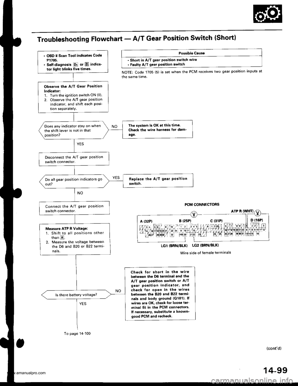
TroubleshootingFfowchart - AIT Gear Position Switch {Short)
Possible Cau3e
. short in A/T gear position switch wire. Faulty A/T gear pGition switch
NOTE: Code 1705 (5) is set when the PCM receives two gear position inputs at
the same time,
PCM CONNECTORS
A (32P1
LGl IBRN/BLK) LG2 (BRN/BLK)
Wire side of female terminals
' O8O ll Scan Tool indicatas Code
P1705.. self-diagnGi3 E or El indica'
tor light blinks five time3
Obs€rve the A/T Goar Position
lndicalor:1. Turn the ignition switch ON (ll).
2. Observe the A/T gear Positionindicator, and shift each Posi'tion seParatelY.
The system is OK at lhis time.
Check the wir€ harne3s fot dam'
age.
Does any indicator stay on when
the shift lever is not in thatposition?
Moasu.e ATP R Voltage:1. Shift to all positions other
than E.2. Measure the voltage between
the D6 and 820 or 822 termi-nals,
Check for short in the wire
betwoon thc DS terminal and tho
A/T gear position switch or A/Tgear porition indicatol, and
check for open in the wires
batween the 820 and 822 t6lmi'
nals and body ground 1G1011. lf
wires are OK, check lor loos€ i€r_
minel fit in the PCM connectors.
lf necBsarv, substittlle a known'good PCM and recheck.
To page'14-100
(cont'd)
14-99
www.emanualpro.com