coolant temperature HONDA CR-V 2000 RD1-RD3 / 1.G User Guide
[x] Cancel search | Manufacturer: HONDA, Model Year: 2000, Model line: CR-V, Model: HONDA CR-V 2000 RD1-RD3 / 1.GPages: 1395, PDF Size: 35.62 MB
Page 207 of 1395
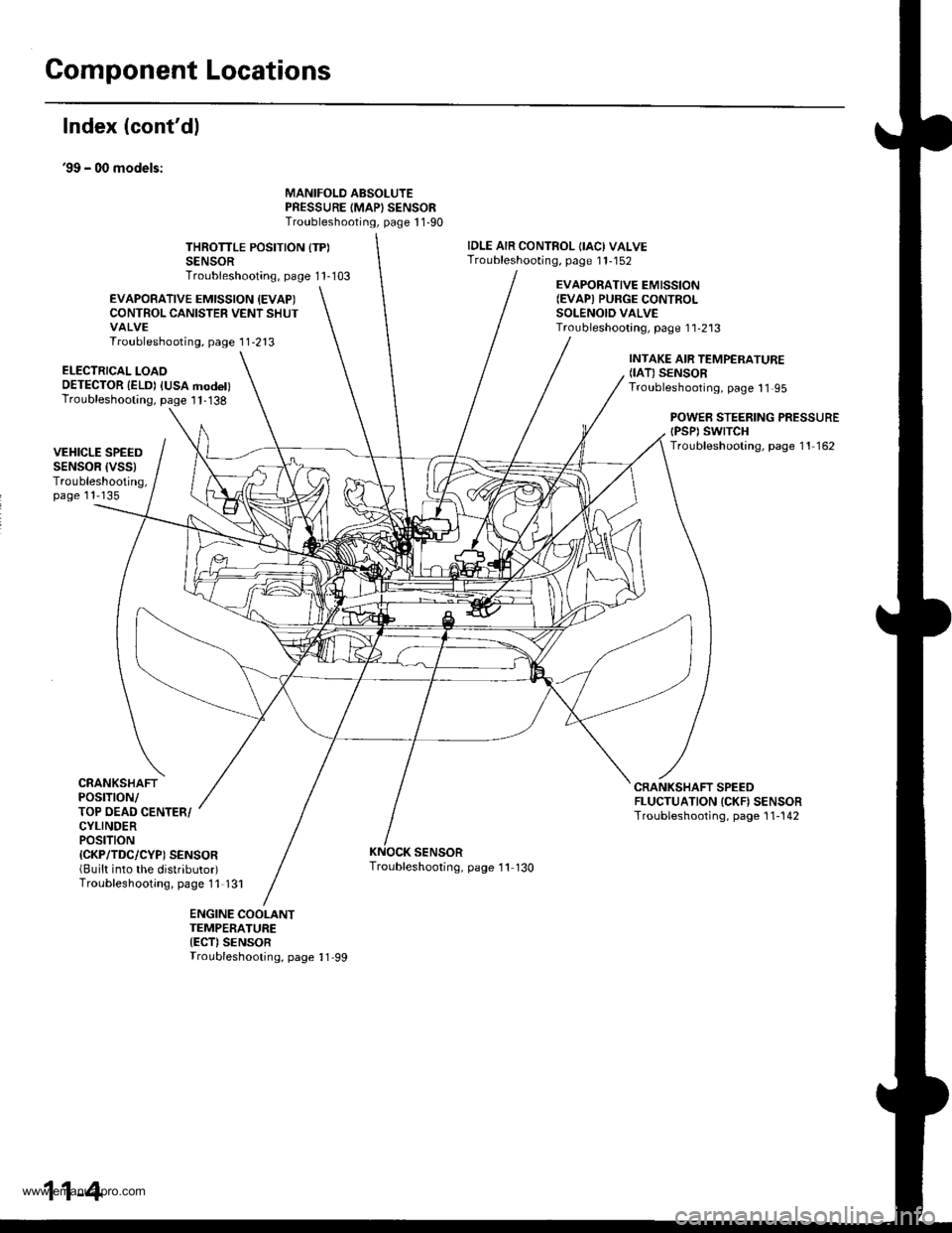
Component Locations
Index (cont'dl
39 - 00 models:
MANIFOLD ABSOLUTEPRESSURE IMAPISENSORTroubleshooting, page 1 1-90
THROTTLE POSITION {TP)SENSORTroubleshooting, page 1 1-103
IDLE AIR CONTROL OACI VALVETroubleshooting, page 1 1-152
EVAPOBATIVE EMISSION {EVAPICONTROL CANISTER VENT SHUTVALVETroubleshooting, page 1 1-213
EVAPORATIVE EMISSION(EVAPI PURGE CONTROI-SOLENOID VALVETroubleshootang, page 1 1-2'13
ELECTRICAL LOAOOETECTOR {ELD) IUSA modet)Troubleshooting, page I 1-138
INTAKE AIR TEMPERATURE(IAT) SENSORTroubleshooting, page 11 95
POWEB STEERING PRESSUREtPsPt swtTcHTroubleshooting, page 11 162VEHICLE SPEEDSENSOR IVSSITroubleshooting,page 11'135
CRANKSHAFTPOSTTTON/TOP OEAD CENTER/CYLINDERPOStTtON{CKP/TDC/CYP) SENSOR(Built into the distributor)Troubleshooting, page 11 131
CRANKSHAFT SPEEDFLUCTUATION ICKN SENSORTroubleshooting, page 1 1-142
SENSORTroubleshooting, page '11 130
ENGINE COOLANTTEMPERATURE{ECT)SENSORTroubleshooting, page 11 99
11-4
www.emanualpro.com
Page 213 of 1395
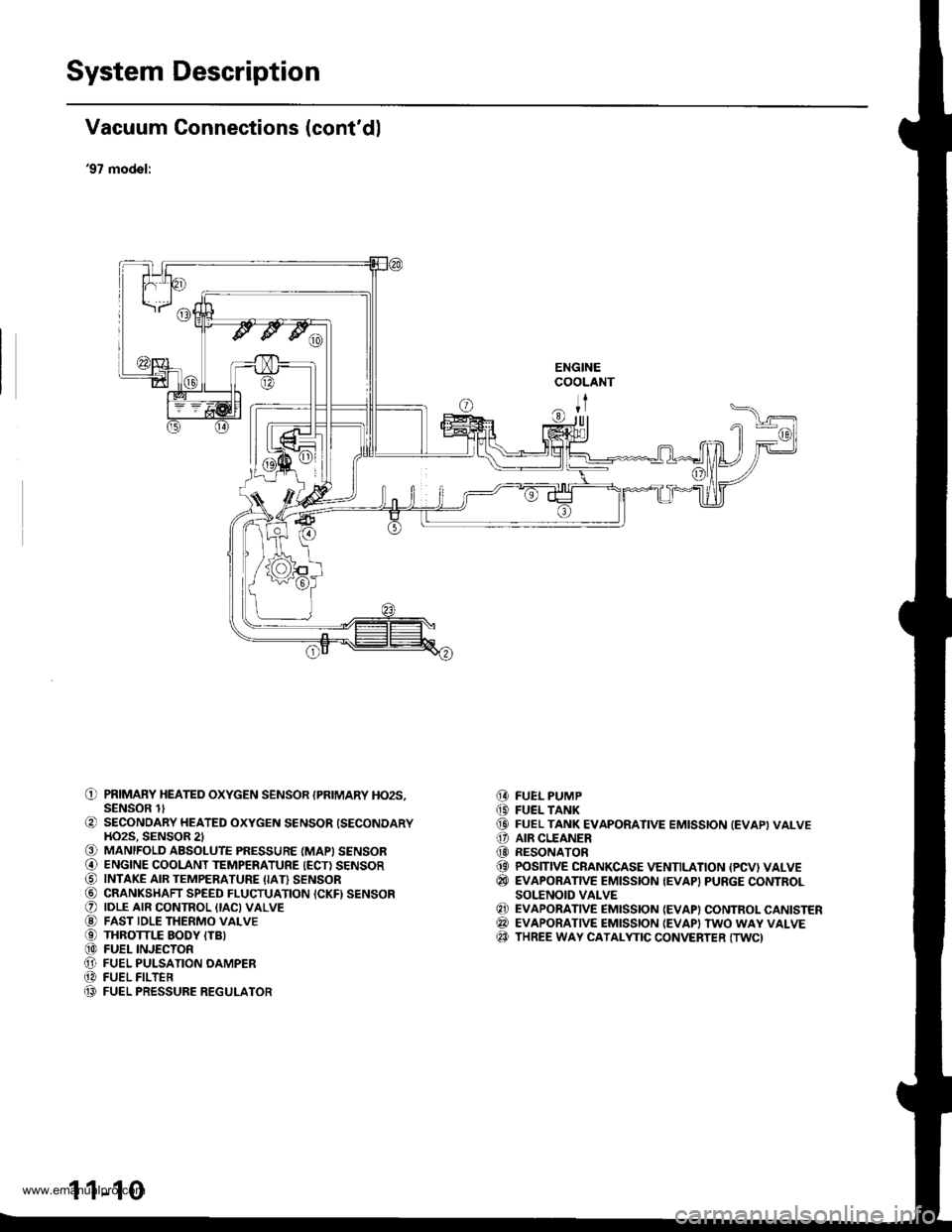
System Description
Vacuum Connections (cont'dl
'97 model:
ENGINECOOLANT
ITr|ll
O PRIMARY HEATED oxYGEN sENsoR {PRIMARY Ho2s,SENSOR lt
O SECONDARY HEATED oxYGEN sENsoR {SECoNDARYHO2S. SENSOR 2l€) MANIFOLD ABSOLUTE PRESSURE (MAPI SENSOR@ ENGINE cooLANT TEMPERATURE {EcT} sENsoRO INTAKE AIR TEMPERATURE (IAI} sENsoR@ CRANKSHAFT SPEED FLUCTUATION ICKFI SENSORO |DLE ArR coNTRoL {tAc)vALvE@ FAST IDLE THERMo vALvEO THRoTTLE EoDY ITB)@ FUEL INJEcTonO FUEL PULSATIoN oAMPER@ FUEL FILTEn(} FUEL PRESSURE REGULATOR
FUEL PUMPFUEL TANKFUEL TANK EVAPORATIVE EMISSION (EVAPIVALVEAIR CLEANERRESONATORPOSITIVE CRANKCASE VENTILATION {PCVI VALVEEVAPORATIVE EMISSION {EVAP} PURGE CONTROLSOI.'ENOID VALVEEVAPORATIVE EMISSION {EVAP) CONTROL CANISTEREVAPORATIVE EMISSION {EVAPI TWO WAY VALVETHREE WAY CATALYTIC CONVERTER (TWC)
@(D(D
o@(}
@
@@@
1 1-10
www.emanualpro.com
Page 215 of 1395
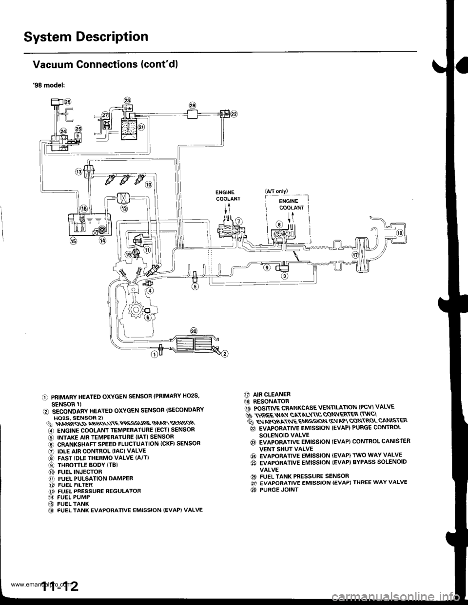
System Description
I
I
I
Vacuum Connections (cont'dl
'98 model:
C PRIMARY HEATEO OXYGEN SENSOR (PRIMARY HO2S,
SENSOR 1)(, SECONDARY HEATEO OXYGEN SENSOR ISECONDARYHO2S, SENSOR 2)(!)\\\\ss\SNBSS\\\ETRESS\RE\\NQ\SE\SSR
G) ENGINE COOLANT TEMPERATUBE (ECT) SENSOR
O INTAKE AIR TEMPERATURE {IAT} SENSOR
@ CRANKSHAFT SPEED FLUCTUATION (CKFI SENSOR
O IDLE AIR CONTROL (IAC) VALVE
@ FAST IDLE THERMO VALVE (A/T)
O THROTTLE BODY (TBI(0) FUEL INJECTOR.1' FUEL PULSATION DAMPER.14 FUEL FILTER(i FUEL PRESSURE REGULATOR14 FUEL PUMP(D FUEL TANK@ FUEL TANK EVAPORATIVE EMISSION {EVAPI VALVE
C] AIR CLEANER(O RESONATOR1iC POSITIVE CRANKCASE VENTILATION (PCV) VALVE
6 \$REE$IN gN NL$\C CON\ER\ER (TNC\
ti q rpos,xr E qN
ssros \E aP cqN\RoLcaNtsr€R
@ EVAPORATIVE EMISSION IEVAP) PURGE CONTROL
SOLENOID VALVEq3 EVAPORATIVE EMISSTON IEVAP} CONTROL CANISTER
VENT SHUT VALVE
@ EVAPORATIVE EMISSION (EVAP) TWO WAY VALVE
€i EVAPORATIVE EMISSION {EVAP) BYPASS SOLENOID
VALVE
€9 FUEL TANK PRESSURE SENSOROi EVAPORATIVE EMISSION {EVAP) THREE WAY VALVE
Qd PURGE JOINT
G/T only)
f
-i*'";-t
COOLANT Jt
U
11-12
www.emanualpro.com
Page 217 of 1395
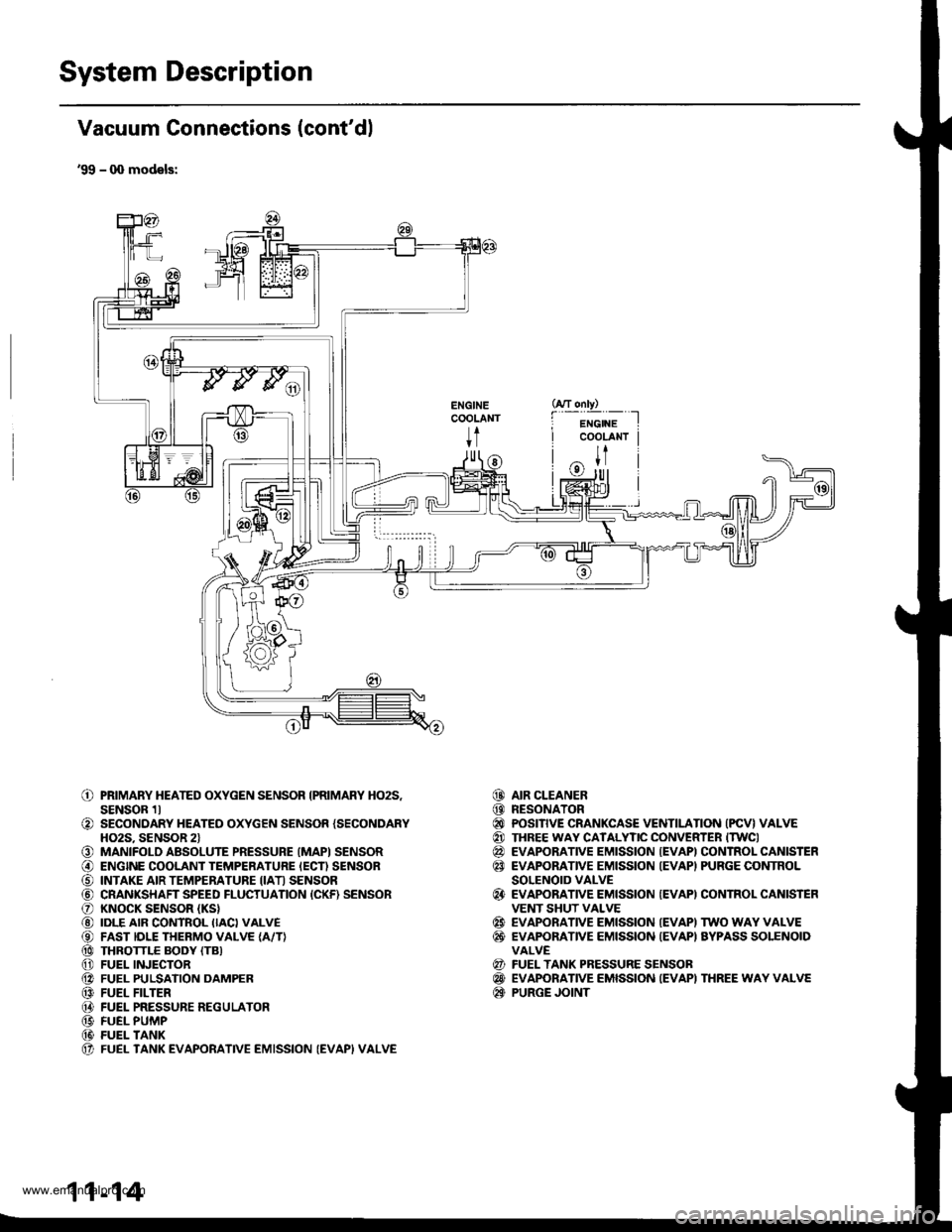
System Description
Vacuum Connections (cont'dl
'99 - q) models:
ENGINECOOLANT
t
o
o
o@
o@@@@@@@@@(t
PRIMARY HEATED OXYGEN SENSOR IPRIMARY HO2S,SENSOR 1lSECONDARY HEATED OXYGEN SENSOR {SECONDARYHO2S. SENSOR 2lMANIFOLD ABSOLUTE PRESSURE (MAPI SENSORENGINE COOLANT TEMPERATURE IECN SENSORINTAKE AIR TEMPERATURE IIATI SENSORCRANKSHAFT SPEED FLUCTUATION {CKF) SENSORKNOCK SENSOR (KS}
IDLE AIR CONTROL IIACI VALVEFAST IDLE THERMO VALVE {A/T}THROTTLE BODY (TB}
FUEL INJECTORFUEL PULSATION DAMPERFUEL FILTERFUEL PRESSURE REGULATORFUEL PUMPFUEL TANKFUEL TANK EVAPORATIVE EMISSION (EVAPI VALVE
AIR CLEANERRESONATORPOSITIVE CRANKCASE VENTILATION (PCV} VALVETHREE WAY CATALYTIC CONVERTER ITWCIEVAPORATIVE EMISSION {EVAPI CONTROL CANISTEREVAPORATIVE EMISSION IEVAPI PURGE CONTROLSOLENOID VALVEEVAPORATIVE EMISSION {EVAPI CONTROL CANISTEFVENT SHUT VALVEEVAPORATIVE EMISSION IEVAPI TWO WAY VALVEEVAPONANVE EMISSION {EVAPI AYPASS SOLENOIDVALVEFUEL TANK PRESSURE SENSOBEVAPORATIVE EMISSION IEVAPI THREE WAY VALVEPURGE JOINT
@@@@@@
@
@@
@@@
11-14
www.emanualpro.com
Page 267 of 1395
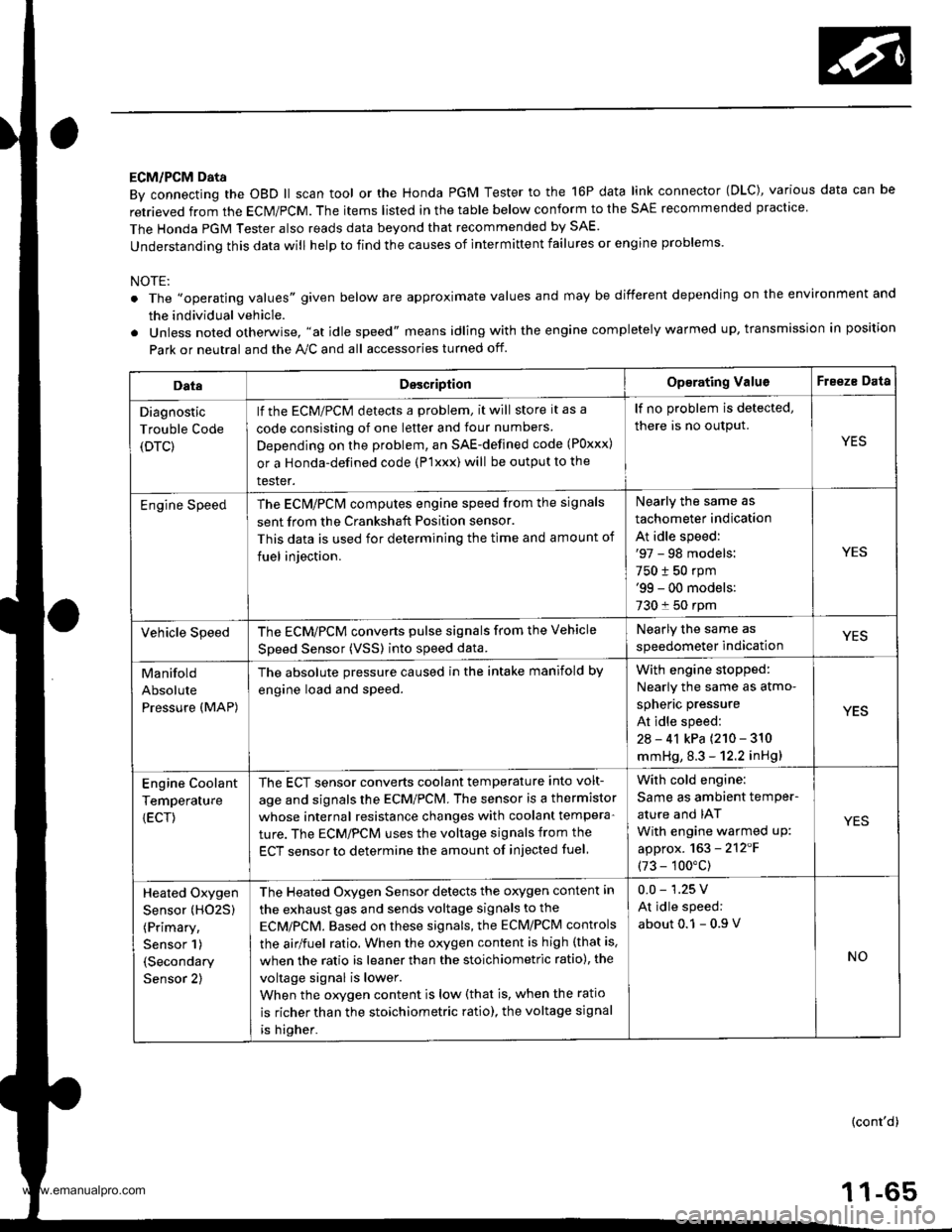
ECM/PCM Data
By connecting the OBD ll scan tool or the Honda PGM Tester to the 16P data link connector (OLC), various data can be
retrieved from the ECM/PCM. The items listed in the table below conform to the SAE recommended practice
The Honda PGM Tester also reads data beyond that recommended by SAE.
understanding this data will help to find the causes of intermittent failures or engine problems.
NOTE:
The ',operating values" given below are approximate values and may be different depending on the environment and
the individual vehicle.
Unless noted otherwise. "at idle speed" means idling with the engine completely warmed up, transmission in position
Park or neutral and the A,./C and all accessories turned otf.
DataDesc.iptionOp€rating ValuoFreeze Data
Diagnostic
Trouble Code
(DTC)
lf the ECM/PCM detects a problem, it will store it as a
code consisting of one letter and tour numbers
Depending on the problem, an SAE-defined code (Poxxx)
or a Honda-defined code (P'lxxx) will be output to the
tester.
lf no problem is detected,
there is no output.
YES
Engine SpeedThe ECN4/PCN4 computes engine speed from the signals
sent from the Crankshaft Position sensor.
This data is used for determining the time and amount of
fuel iniection.
Nearly the same as
tachometer indication
At idle speed:'97 - 98 models:
750 t 50 rpm'99 - 00 models:
730 f 50 rpm
YES
Vehicle SpeedThe ECM/PCM converts pulse signals from the Vehicle
Speed Sensor (VSSI into speed data.
Nearly the same as
speedometer indicationYES
Manifold
Absolute
Pressure (MAP)
The absolute pressure caused in the intake manifold by
engine load and speed.
With engin6 stopped:
Nearly the same as atmo-
spheric pressure
At idle speed:
2a - 41 kPa {210 - 310
mmHg, 8.3 - 12.2 inHg)
YES
Engine Coolant
Temperature
{ECT)
The ECT sensor converts coolant temperature into volt-
age and signals the ECM/PCM. The sensor is a thermistor
whose internal resistance changes with coolant tempera-
ture. The ECM/PCM uses the voltage signals from the
ECT sensor to determine the amount of injected fuel
With cold engine:
Same as ambient temPer-
ature and IAT
With engine warmed uP:
approx. 163 - 2'12'F
(73 - 100"c)
YES
Heated Oxygen
Sensor (HO25)
(Primary,
Sensor 1)
(Secondary
Sensor 2)
The Heated Oxygen Sensor detects the oxygen content in
the exhaust gas and sends voltage signals to the
ECMiPCM. Based on these signals, the ECM/PCM controls
the airlfuel ratio. When the oxygen content is high (that is.
when the ratio is leaner than the stoichiometric ratio), the
voltage signal is lower.
When the orygen content is low (that is, when the ratio
is richer than the stoichiometric ratio), the voltage signal
is higher.
0.0 - 1.25 V
At idle speed:
about 0.1 - 0.9
NO
(cont'd)
1 1-65
www.emanualpro.com
Page 272 of 1395
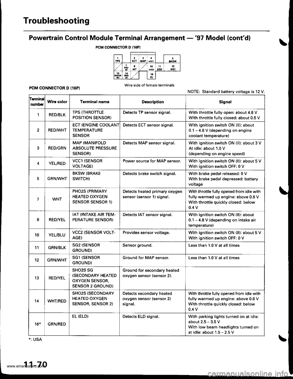
Troubleshooting
Powertrain Gontrol Module Terminal Arrangement -'97 Model (cont'd)
PCM CONNECTOR O {16PI
PCM CONNECTOR D (I6P)Wire side of f6male terminals
NOTE: Standard battery voltage is 12 V.
f.rminal
numbcrWir! colorT€rminal nam6DescriptionSignal
1RED/BLKTPS ffHROTTLE
POSITION SENSOR}
Detects TP sensor signal.With throttle fullv oDen: about 4.8 V
With throttle fullv closed: about 0.5 V
RE D,4/VHT
ECT (ENGINE COOLANT
TEMPERATURE
SENSOR
Detects ECT sensor signal.With ignition switch ON {ll): about
0.1 - 4.8 V (depending on engine
coolant temperature)
RED/GRN
MAP (MANIFOLD
ABSOLUTE PRESSURE
SENSOR)
Detects MAP sensor signal.With ignition switch ON (ll): about 3 V
At idle; about 1.0 V(depending on engine speed)
YEUREDVCCl (SENSOR
VOLTAGE)
Pow€r source for MAP sensor.With ignition switch ON (ll): about 5 V
With ignition switch OFF: 0 V
EG R N/WHT
BKSW (BRAKE
SWITCH)
Detects brake switch signal.With brake pedal released:0 V
With brake pedal depressed: battery
voltage
7WHT
PHO2S (PRIMARY
HEATED OXYGEN
SENSOR SENSOR 1)
Detects heated primary oxygen
sensor (sensor 1) signal.
With throttle fully opened from idle with
fully warmed up engine: above 0.6 V
With throttle quickly closed: below
0.4 v
8RED//E L
IAT (INTAKE AIR TEM.
PERATURE SENSOR)
Detects IAT sensor signal.With ignition switch ON lll): about
0.1 - 4.8 V (depending on intake air
temperaturel
10YEUBLUVCC2 (SENSOR VOLT-
AGEI
Provides sensor voltage.With ignition switch ON (ll): about 5 V
With ignition switch OFF: 0 V
11GRN/BLKSG2 (SENSOR
GROUND)
Sensor ground.Less than 1.0 V at all times
12GRN/WHTSGl (SENSOR
GROUND)
Ground for MAP sensor.Less than 1.0 V at all times
13RED/YE L
SHO2S SG(SECONDARY HEATED
OXYGEN SENSOR,
SENSOR 2 GROUND)
Ground for secondary heated
orygen sensor (sensor 2).
14WHT/RED
SHO2S (SECONDARY
HEATED OXYGEN
SENSOR, SENSOR 2)
Detects secondary heated
orygen sensor (sensor 2)
signal,
With throttle fully opened from idle with
fully warmed up engine; above 0.6 V
With throttle quickly closed: below
0.4 v
16*GRN/RED
EL (ELD)Detects ELD signal.With parking lights turned on at idle
about 2.5 - 3.5 V
With low beam headlights turned on
at idle: about 1.5 - 2.5V
1-70
www.emanualpro.com
Page 275 of 1395
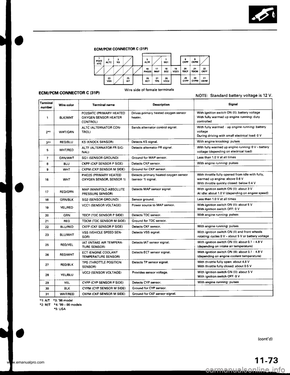
ECM/PCM CONNECTOF C (31PI
Wire side o{ female terminal€ECM/PCM CONNECTOR C (31P)NOTE: Standard battery voltage is 12 V.
TermidalD.3criptionSignal
8LI(WHTPOzSHTC {PRIII4ABY HEATEDOXYGEN SENSOR HEATERCONTROL)
Drivss prim6ry h$ted oxygsn sensorWilh ignition switch ON (ll): baneryvoltsgeWith ftrllywarmsd up €ngine runnang: duty
2"WHT/GBNALTC (ALTERNATOR CON,TROL)Sonds alternalor control signsl.With fully wafmod up €ngine rnningr ban€ryvoltagoDu ng driving with small elsctrical lo6d: 0 v
3'1FED/8LUKS (KNOCK SENSOR)Dstects KS signal.With engine knockang: pulses
5WHT/REDALTF (ALTERNATOR FR SIG-NAL}Detects alternator FR signal.Wth fullywarmed up €ngine running:0 V-batteryvoltag€ {d€pending on slsctrical load)
1GRN,4trHTSG1 (SENSOR 680UND}Ground for l/tAP sensor.L€ss than 1.0 v 6t all times
8BLUCKPP (CKP SENSOF P SIDE)Dat€cls CKP s6nsor.With €ngin€ runningr puls€s
9CKPI.,I| {CKP SENSOF M SIDE)Ground for CKP s€nsor.
15PHO2S {PRIMARY HEATEDOXYGEN SENSOR, SENSOR 1)Detocts pfimary he6t6d oxygen ssnsor
{sonsor 1)signal.with ihfottls fully opened from idle with fully,
walm6d up engins: above 0.6 VWith throttlo quickly clossd: below 0.4 v
17RED/GRNMAP (MANIFOLD ABSOLUTEPRESSURE SENSOR)
D6tects MAP s€nsor sign6l.With ignition switch ON (ll):about 3 VAt idls: aboul 1.0 V {dspsnding on engine speed)
18GRN/BLKSG2 (SENSOB GNOUNDiLsss than 1.0 V at all tim€s
19YEUBEDVCCl {SENSOR VOLTAGE)Power soufce to MAP s€nsor.With ignition switch ON (ll): about 5 VWith ignition switch OFF:0 V
20GRNTDCP {TDC SENSOR P SIDE)Derecis TDC sensor.With engine funning: Pulses
2lREDTDCM ITDC SENSOR M SID€)Ground for TDC sensor.
22BLU/REDCKFP (CKF SENSOR PSIDE)Dstscts CKF s€nsor.With sngins running: pulsss
23BLU/WHTVSS (VEHICLE SPEED SEN-soR)Dstscrs vss signal.With ignition switch ON (ll)and front wheelsrotaringrcyclss 0 v- 6bout 5 V or ban€ry voltage
25RED//ELIAT (INTAKE AIR TEMPERA'TURE SENSOB)Detacts IAT sensor signal.With igniiion switch ON (ll): about 0.1 - 4.8 V(d€p€nding on iniate air t€mp€raturc)
26REO/WHTECT {ENCINE COOLANTTEMPERATURE SENSOR)oetscts ECT sensor signal.With ignition switch ON (ll): about 0.1 4.8 V
{doponding on 6ngin€ coolanl lemper6tu16)
27RED/BLKTPS (THROTTLE POSITIONSENSOR)Dotects TP sensor signrl.with rhrottls fully op€n: aboui 4.8 vwith throtrl6 fullyclosed: about 0.5 v
2AYEUBLUVCC2lSENSOR VOLTAG€}Provid€s s€nsor voltage.With ignilion switch ON (ll): about 5 VWhh ignition switch OFF: 0 V
29YELCYPP ICYP SENSO8 P SIDE)Dsrscts CYP sensor.With €ngins runningr pulsss
30BLKCYPM (CYP SENSOR M SIDE)Ground for CYP sansor.
31WHT/REDCKFM {CKF SENSOR M SIDE)6.ound lof CKF ssnsor signal.
11. AfT 13. '94 model'2:M/T 14:'99- 0o modsls.5: USA
(cont'd)
11-73
www.emanualpro.com
Page 277 of 1395
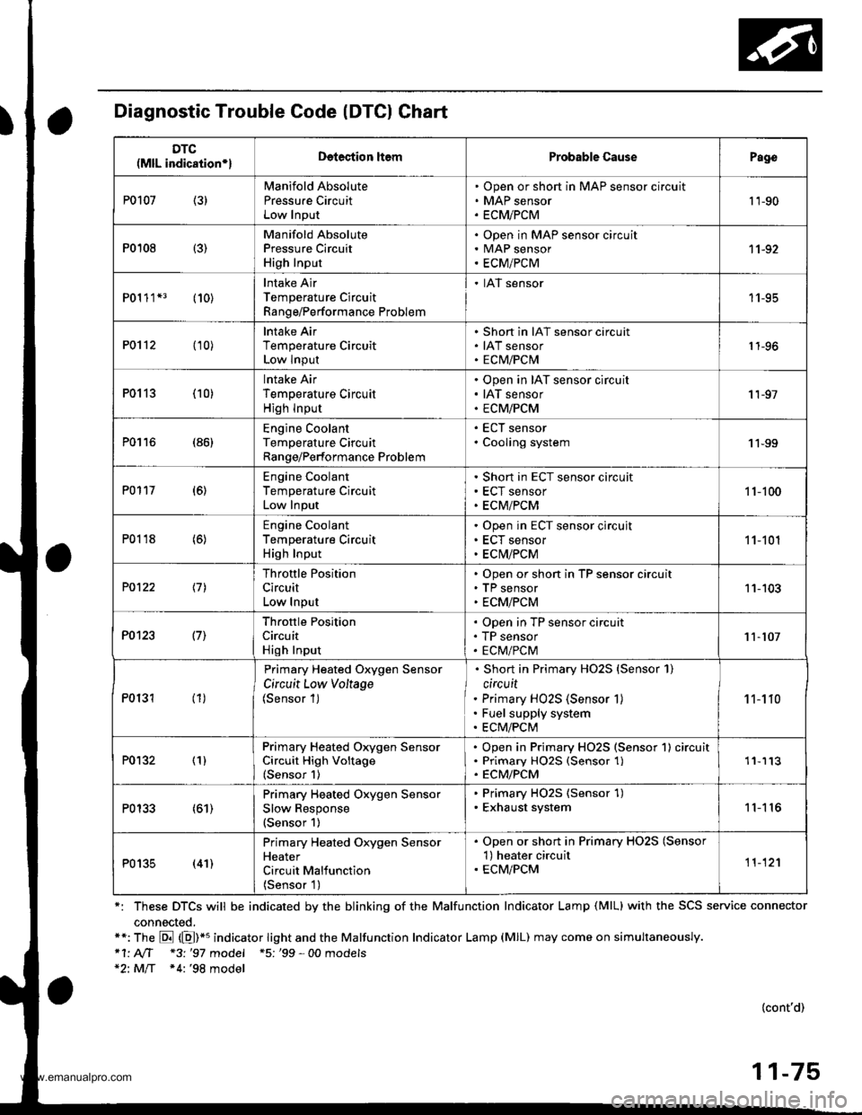
Diagnostic Trouble Code (DTCI Chart
*: These DTCS will be indicated by the blinking of the Malfunction Indicator Lamp (MlL) with the SCS service connector
connected.**: The E (E)*u indicator tight and the Malfunction Indicator Lamp (MlL) may come on simultaneously.*1' AIT *3 '97 model +5; '99 - 00 models*2: MlT *4:'98 model
{cont'd)
11-75
DTC(MlL indication*lDetection ltemProbable CausePago
P0107 (3)Manifold Absolute
Pressu.e CircuitLow Input
Open or short in MAP sensor circuit
MAP sensor
ECMiPCM
't 'l-90
P0108 {3)
Manifold AbsolutePressure Circuit
High Input
Open in MAP sensor circuitMAP sensor
ECM/PCM
11-92
P01 1 1*3 (10)Intake Air
Temperature Circuit
Range/Performance Problem
. IAT sensor
11-95
P0112 (10)lntake Air
Temperature CircuitLow Input
Short in IAT sensor circuit
IAT sensorECM/PCM1 1-96
P0113 (10)lntake Air
Temperature Circuit
High lnput
Open in IAT sensor circuit
IAT sensor
ECM/PCM
'I 1-97
P0116 (86)Engine CoolantTemperature CircuitRange/Performance Problem
ECT sensor
Cooling system1 1-99
P0117 (6)Engine Coolant
Temperature Circuit
Low Input
Short in ECT sensor circuit
ECT sensor
ECM/PCM
1 1-100
P0118 (6)Engine Coolant
Temperature CircuitHigh Input
Open in ECT sensor circujt
ECT sensor
ECM/PCM
11-101
P0122 \11
Throttle Position
Circuit
Low Input
Open or short in TP sensor circuitTP sensor
ECM/PCM
11-103
P0123 l7l
Throftle Position
Circuit
High Input
Open in TP sensor circuit
TP sensor
ECM/PCM11-107
P0131 (1)
Primary Heated Oxygen Sensor
Circuit Low Voltage(Sensor 1)
Short in Primary HO2S {Sensor 1)
circuit
Primary HO2S (Sensor 1)
Fuel supply system
ECM/PCM
1 1-1 10
P0132 (1)Primary Heated Orygen SensorCircuit High Voltage(Sensor 1)
Open in Primary HO2S (Sensor 1) circuitPrimary HO25 (Sensor 1)ECM/PCM
'11113
P0133 (61)Primary Heated Oxygen Sensor
Slow Response(Sensor 1)
. Primary HO2S (Sensor 1). Exhaust system11'I 16
P0135 (41)
Primary Heated Oxygen SensorHeater
Circuit Malfunction
{Sensor 1)
. Open or short in Primary HO2S (Sensor'l) heater circuit. ECM/PCM11-12'l
www.emanualpro.com
Page 282 of 1395

PGM-FI System
System Description
INPUTS
CKP/TDC/CYP Sensor
CKF Sensor
MAP Sensor
ECT Sensor
IAT Sensor
TP Sensor
Primary HO2S
Secondary H02S
vss
KS*5
BARO Sensor
ELD*6
Starter Signal
ALT FR Signal
Air Conditioning Signal
Ay'T Gear Position Signal*1
Baftery Voltage (lGN.1)
Brake Switch Signal
PSP Switch Signal
Fuel Tank Pressuae Sensor*4. *5
Countershaft Speed Sensor*1
Mainshaft Speed Sensor*r
OVER-DRIVE Switch Signal*s
ENGINE CONTROL MODULE (ECM)/
POWERTRAIN CONTROL MODULE (PCM) OUTPUTS
|iuel 1"j""- Th,rhg ""d Drrafr";-l
Et*-.nt"tdt"cont.orl
to,r*,c;;trffi;]
l.----.---:. .Lrgnrnon |lmrng Lonrror I
Ecir/PcM B*k',p Fr""il]
m;"t-ll-r*'io*l
Fuel Injectors
PGM-Fl Main Relay (Fuel Pump)
MIL
IAC Valve
Ay'C Compressor Clutch Relay
Radiator Fan Relay
Condenser Fan Relay
ALT
tcM
EVAP Purge Control Solenoid
Valve
Primary HO2S Heater
Secondary H02S HeaterEVAP Bypass Solenoid Valve*a *5
EVAP Control Canister Vent Shut
DLC
Lock-up Control Solenoid Valve*l
Shift Control Solenoid Valve*1
Ay'T Clutch Pressure Control
Solenoid Valve*1
D4 Indicator Light'1 *3, *a
D Indicator Light,l *5
OVER-DRIVE OFF Indicator
Lighl*t *:
*1: A/T {3:'97 model'2: M/f +4:'98 model*5: '99 - 00 models"6: USA
PGM-Fl System
The PGM-Fl system on this model is a sequential multiport fuel injection system.
Fuel iniecior Timing and Duration
The ECM/PCM contains memories for the basic discharge durations at various engine speeds and manifold pressure. The
basic discharge duration, after being read out from the memory, is further modified by signals sent from various sensors
to obtain the final discharge duration.
ldle Air Control
ldle Air Control Valve (lAC Valve)
When the engine is cold, the Ay'C compressor is on, the transmission is in gear, the brake pedal is depressed, the P/S load
is high, or the alternator is charging, the ECM/PCM controls current to the IAC Valve to maintain the correct idle speed.
lgnition Timing Control
o The ECM/PCM contains memories for basic ionition timing at various engine speeds and manifold air flow rates.
lgnition timing is also adjusted for engine coolant temperature.
. A knock control system was adopted which sets the ideal ig nition timing for the octane rating of the gasoline used.*s
Other Control Funstions
1. Starting Control
When the engine is started. the ECM/PCM provides a rich mixture by increasing fuel injector duration.
2. Fuel Pump Control
. When the ignition switch is initially turned on (ll). the ECMiPCM suppli€s ground to the PGM-FI main relay that
supplies current to the fuel pump for two seconds to pressurize the fuel system.
. When the engine is running, the ECM/PCM supplies ground to the PGM-FI main relay that supplies current to the
fuel oumo.
. When the engine is not running and the ignition is on, the ECM/PCM cuts ground to the PGM-FI main relay which
cuts current to the fuel pump.
1 1-80
www.emanualpro.com
Page 283 of 1395

Fuel Cut-off Control
. During deceleration with the throttle valve closed, current to the fuel injectors iscutoffto improvefuel economyat
speeds over 970 rpm ('97 - 98 models), 920 rpm ('99 - 00 modelsl.
. Fuel cut-off action also takes place when engine speed exceeds 6,500 rpm ('97 - 98 models), 6900 rpm ('99 - 00
models), regardless of the position of the throttle valve, to protect the engine from over-rewing.
With Ay'T model. the PCM cuts the fuel at engine speeds over 5,000 rpm when the vehicle is not moving.*'�
4,./C Comoressor Clutch Relav
When the ECM/PCM receives a demand for cooling from the air conditioning system, it delays the compressor from
being energized, and enriches the mixture to assure a smooth transition to the Ay'C mode.
Evaporative Emission (EVAP) Purge Control Solenoid Valve
When the engine coolant temperature is above 154"F (68'C), the ECM/PCM controls the EVAP purge control solenoid
valve which controls vacuum to the EVAP purge control canister,
Alternator Control
The system controls the voltage generated at the alternator in accordance with the electrical load and driving mode.
which reduces the engine load to improve the fuel economy.
PCM Fail-saf e/Back-up Functions
1. Fail-safe Function
When an abnormality occurs in a signal from a sensor, the ECM/PCM ignores that signal and assumes a pre-pre
grammed value for that sensor that allows the engine to continue to run.
2. Back-up Function
When an abnormality occurs in the ECM/PCM itself, the fuel injectors are controlled by a back-up circuit independent
of the system in order to permit minimal driving.
3. Self-diagnosis Function IMalfunction Indicator Lamp (MlL)l
When an abnormality occurs in a signal from a sensor, the ECM/PCM supplies ground for the MIL and stores the DTC
in erasable memory. When the ignition is initially turned on {ll), the ECM/PCM supplies ground for the MIL for two
seconds to check the MIL bulb condition.
4. Two Trio Detection Method
To prevent false indications, the Two Trip Detection Method is used for the HO2S*1, fuel metering-related. idle control
system, ECT sensor and EVAP control system self-diagnostic functions. When an abnormality occurs, the ECM/PCM
stores it in its memory. When the same abnormality recurs after the ignition switch is turned OFF and ON (ll) again,
the ECM/PCM informs the driver by lighting the MlL. However, to ease troubleshooting, this function is cancelled
when you jump the service check connector, The MIL will then blink immediately when an abnormality occurs.
5. Two (or Three) Driving Cycle Detection Method {'97 model)
A "Driving Cycle" consists of starting the engine, beginning closed loop operation, and stopping the engine. lf misfir-
ing that increases emissions or EVAP control system malfunction is detected during two consecutive driving cycles.
or TWC deterioration is detected during three consecutive driving cycles, the ECM/PCM turns the MIL on. However, to
ease troubleshooting, this function is cancelled when you jump the service check connector. The MIL will then blink
immediately when an abnormality occurs.
*1: '97 - 98 models*2: '99 - 00 models
5.
www.emanualpro.com