differential mount HONDA CR-V 2000 RD1-RD3 / 1.G User Guide
[x] Cancel search | Manufacturer: HONDA, Model Year: 2000, Model line: CR-V, Model: HONDA CR-V 2000 RD1-RD3 / 1.GPages: 1395, PDF Size: 35.62 MB
Page 807 of 1395

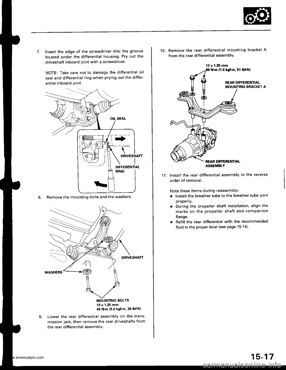
7. Insert the edge of the screwdriver into the groove
located under the differential housing Pry out the
driveshaft inboard ioint with a screwdraver.
NOTE: Take care not to damage the differential oil
seal and differential ring when prying out the differ-
ential inboard joint.
8. Remove the mounting bolts and the washers.
DRIVESHAFT
MOUNTING BOLTS'10 x 1 .25 mm,19 N'm (5 0 kgf m, 36 lbtftl
Lower the rear differential assembly on the trans-
mission jack, then remove the rear driveshafts from
the rea r difterential assembly.
DIFFERENTIAL
12 x 1.25 fifi
10. Remove the rear difterential mounting bracket A
from the rear differential assembly.
N.m {7.0 lgf.m. 5l lbl.tt)
REAR DIFFERENTIALMOUNTING BRACKET A
REAN DFFERENTI,ALASSEMBLY
11.Install the rear differential assembly in the reverse
order of removal.
Note these items during reassembly
. lnstall the breather tube to the breather tube joint
properly.
. During the propeller shaft installation, align the
marks on the propeller shaft and companion
flange.
. Reiill the rear differential with the recommended
fluid to the proper level {see page 15-14).
15-17
www.emanualpro.com
Page 813 of 1395
![HONDA CR-V 2000 RD1-RD3 / 1.G User Guide
Reassembly
1. Apply CVT fluid to the rubber of the oil strainer, then
install the oil strainer, the magnet, and the oil pump
pin to the differential carrier.
OIL PUMP PIN
DIFFERE]TTIAL CARRIERASSEMBL HONDA CR-V 2000 RD1-RD3 / 1.G User Guide
Reassembly
1. Apply CVT fluid to the rubber of the oil strainer, then
install the oil strainer, the magnet, and the oil pump
pin to the differential carrier.
OIL PUMP PIN
DIFFERE]TTIAL CARRIERASSEMBL](/img/13/5778/w960_5778-812.png)
Reassembly
1. Apply CVT fluid to the rubber of the oil strainer, then
install the oil strainer, the magnet, and the oil pump
pin to the differential carrier.
OIL PUMP PIN
DIFFERE]TTIAL CARRIERASSEMBLY
Align the oil pump pin with the groove of the rear oil
pump in the pump body assembly, then install the oil
pump body assembly to the differential carrier assem-
oty.
-n
CWfluid
2.
MAGNET
OIL PUMP BODY ASSEMBLY
3. Tighten the oil pump body assembly mounting
bolts.
4. Install the oil pump driveshaft by aligning the pro-
jection of the oil pump driveshaft with the groove of
the front oil pump in the oil pump body assembly.
lnstall in this direction.
Projection
6x1.0mm12 N.m 11.2 kg{.m,8.7 lbl.ft}
Install the thrust needle bearing.
Install the pressure plate assembly by aligning the
projection of the pressure plate with the groove of
the oil pump driveshaft.
5.
OIL PUMPDRIVESHAFT
(cont'd )
15-23
THRUST NEEDLE BEABING
PRESSURE PLATE
www.emanualpro.com
Page 843 of 1395

Rear Driveshafts
Reassembly (cont'd)
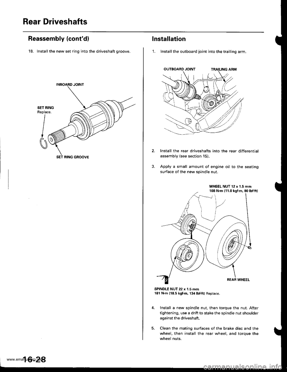
18. Install the new set ring into the driveshaft groove.
SET RINGReplace.
I
CI
SET RING GROOVE
16-2A
lnstallation
'1. lnstall the outboard joint into the trailing arm.
Install the rear driveshafts into the rear differential
assembly (see section 15).
Apply a small amount of engine oil to the seating
surface of the new spindle nut.
SPINDLE NUT 22 x 1.5 mm181 N.m (18.5 kgf.m, 134lbl.ftl Replace.
Install a new spindle nut, then torque the nut. After
tightening, use a drift to stake the spindle nut shoulder
against the driveshaft.
Clean the mating surfaces of the brake disc and the
wheel, then install the rear wheel, and torque the
wheel nuts.
WHEEL NUT 12 x 1.5 mm108 N.m (11.0 kgt.m, 80lbtftl
www.emanualpro.com
Page 845 of 1395

Propeller Shaft
RemovaUlnstallation
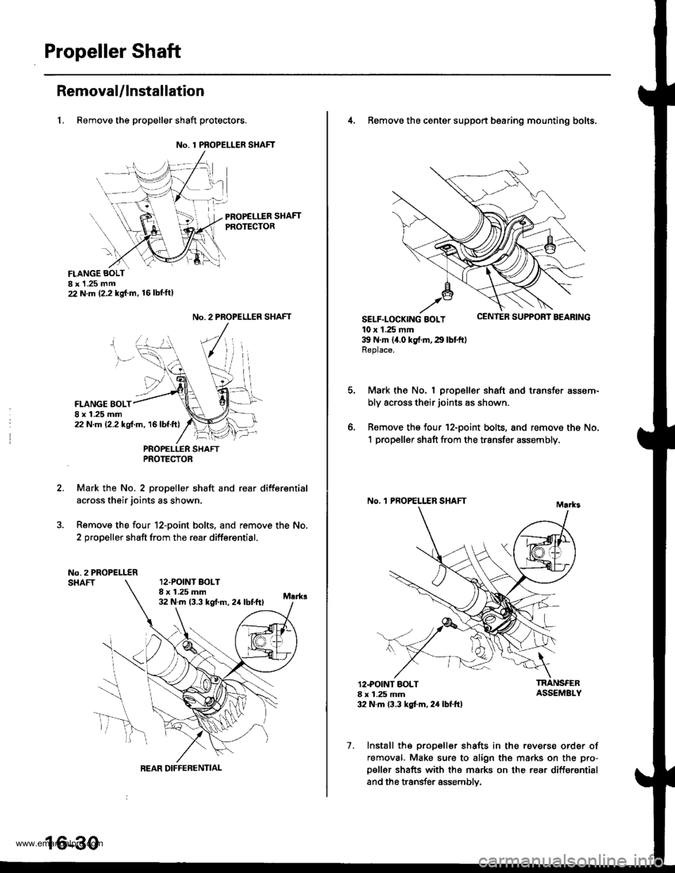
1, Remove the propeller shaft protectors.
No. 1 PROPELLER SHAFT
PROPELLER SHAFTPROTECTOR
FLANGE BOLTI x 1 .25 mm22 N.m (2.2 kg{.m. 16lbl'ft)
2.
No. 2 PROPELLER SHAFT
FLANGE BOLT8 x 1.25 mm22 N.m 12.2 kgf.m, 16lbf.ft)
PNOPELLER SHAFTPROTECTOR
Mark the No. 2 propeller shaft and rear differsntial
across their joints as shown.
Remove the four 12-point bolts. and remove the No.
2 propeller shaft from the rear differential.
No.2 PROPELLERSHAFT12.POINT BOLT8 x 1.25 mm32 N.m 13.3 kst m, 24 lbtftl
REAR DIFFERENTIAL
16-30
4, Remove the center support bearing mounting bolts.
SELF-LOCK|NG BOLT uErr rEn Durrr.r'r I I'EAnrNu
10 x 1.25 mm39 N'm 14.0 kg{.rn,29 lbtftlReplace.
Mark the No. I propeller shaft and transfer assem-
bly across their joints as shown.
Remove the four 12-point bolts, and remove the No.
1 propeller shaft from the transfer assembly,
No. 'l PROPELLER SHAFT
o.
12.POINT BOLT8 x 1.25 mm32 N.m 13.3 kgt'm, 2,1 lbf.ft)
TRANSFERASSEMBLY
7. Install the propeller shafts in the reverse order of
removal. Make sure to align the marks on the pro-
p€ller shafts with the marks on the rear differential
and the transfer assemblv.
www.emanualpro.com