rear arm HONDA CR-V 2000 RD1-RD3 / 1.G User Guide
[x] Cancel search | Manufacturer: HONDA, Model Year: 2000, Model line: CR-V, Model: HONDA CR-V 2000 RD1-RD3 / 1.GPages: 1395, PDF Size: 35.62 MB
Page 903 of 1395
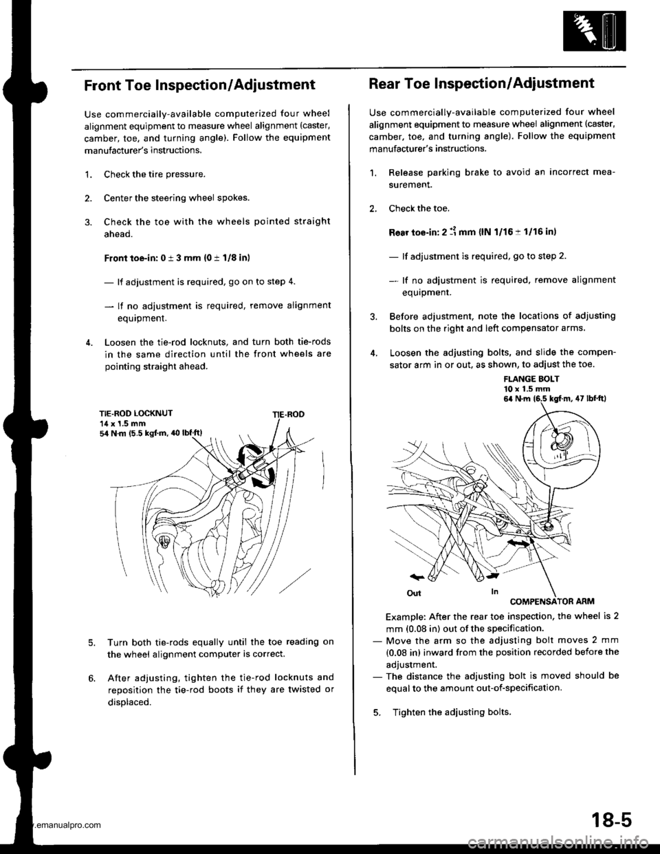
Front Toe Inspection/Adjustment
Use commercially-available computerized four wheel
alignment equipment to measure wheel alignment (caster,
camber, toe, and turning angle). Follow the equipment
manufacturer's instructions,
3.
1.Check the tire pressure.
Center the steering wheel spokes.
Check the toe with the wheels pointed straight
ahead.
Front toe-in: 0 i 3 mm {0 t 1/8 inl
- lf adjustment is required, go on to step 4.
- lf no adjustment is required, remove alignment
equipment.
Loosen the tie-rod locknuts, and turn both tie-rods
in the same direction until the front wheels are
pointing straight ahead.
5.Turn both tie-rods equally until the toe reading on
the wheel alignment computer is correct.
After adjusting, tighten the tie-rod locknuts and
reposition the tie-rod boots if they are twisted or
displaced.
sir N m (5.5 kgJ.m, 'O lbf.ft)
Rear Toe Inspection/Adjustment
Use commercially-available computerized four wheel
alignment equipment to measure wheel alignment (caster,
camber. toe, and turning angle). Follow the equipment
manufacturer's instructions.
Release parking brake to avoid an incorrect mea-
surement.
Check the toe.
Ro8r toe-in: 2 :1 mm {lN l/16:t 1/16 in,
- lf adjustment is required, go to step 2.
- lf no adiustment is required. remove alignment
equrpmenr.
Before adjustment, note the locations of adjusting
bolts on the right and left compensator arms.
Loosen the adjusting bolts, and slide the compen-
sator arm in or out. as shown, to adiust the toe.
1.
FLANGE BOLT'10 x 1.5 mm
COMPENSATOR ARM
Example: After the rear toe inspection, the wheel is 2
mm (0.08 in) out of the specification.- Move the arm so the adjusting bolt moves 2 mm
{0.08 in) inward from the position recorded before the
adjustment.- The distance the adjusting bolt is moved should be
equal to the amount out-of-specification.
5. Tighten the adjusting bolts.
6a N.m 16.5 kgf.m, 47 lbf'ftl
18-5
www.emanualpro.com
Page 917 of 1395
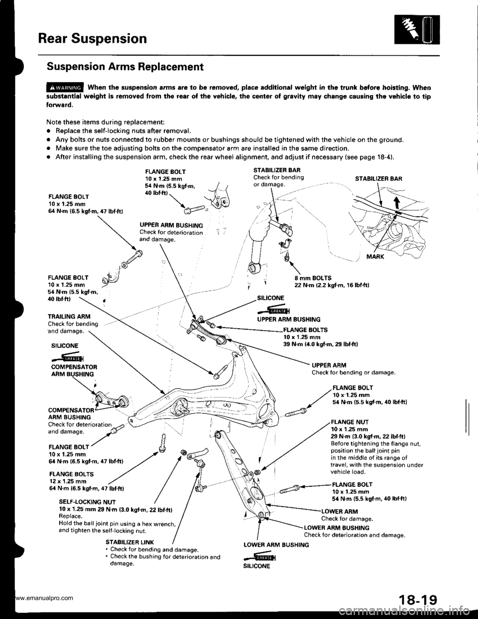
Rear Suspension
Suspension Arms Replacement
@ when the suspension arms are to be removed, plsce additional weight in lhe trunk beto.o hoisting. when
substantial weight is removed from the rear of the vehicle, the center ot grsvity m8y chango causing the vehicle to tip
forward.
Note these items during replacement:
. Replace the self-locking nuts after removal.
. Any bolts or nuts connected to rubber mounts or bushings should be tightened with the vehicle on the ground.
. Make sure the toe adjusting bolts on the compensator arm are installed in the same direction,
. After installing the suspension arm, check the rear wheel alig nment, and adjust if necessa ry (see page 18-4),
STABILIZER BARCheck for bendingor oamage.
FLANGE EOLT10 x 1.25 mm64 N.m 16.5 kgf.m,47 lbf.ft)
FLANGE BOLT10 x 1.25 mm54 N.m (5.5 kgt.m, / t40 lbf.ftt. --1 \ \A1(\
\a'v..:r
UPPER ARM BUSHINGCheck for deteriorationand damage.
il ,
FLANGE BOLT'l0 r 1.25 mm54 N.m (5.5 kgf.m,
8 mm EOLTS22 N.m {2.2 kgf.m, 16 bl.ftl
40 rbtft)
'ano oamage.
TRAILING ARMCheck for bending
stLtcoNE
-6lUPPER ARM
COMPENSATORARM BUSHING
64 N.m 16.5 kgf.m, 47 lbtftl
SELF.LOCKING NUT
BUSHING
FLANGE BOLT10 x 1.25 mm54 N.m {5.5 kgf.m, 40 lbf.ft}
FLANGE BOLTS10 x 1.25 mm39 N.m 14.0 kgf.m, 29 lbf.ft)stLtcoNE
.@iCOMPENSATORARM BUSHING
UPPER ARMCheck lor bending or damage.
FLANGE NUT10 x 1 .25 mm29 N.m {3.0 kg{.fl,22 lbf.ft}Before tightening the flange nut,position the balljoint pinin the middle of its range oftravel, with the suspension undervehicle load.
10 x 1.25 mm 29 N.m (3.0 kgl.m, 22 tbf.ft)Replace.Hold the ball ioint pin using a hex wrenct,,and tighten the self-locking nut.
STABILIZER LINK
Check tor damage.
LOWER ARM BUSHINGCheck for deterioration and damage.
. Check for bending and damage.. Check the bushing tor deterioration anddamage.
LOWEN ARM
-6ilstLrcoNE
STABILIZER 8AR
,/ FLANGE BOLT
// 10 x 1.25 mm
^/ s4 N.m 15.5 kst'm, 40 lbf ftl
BUSHING
www.emanualpro.com
Page 918 of 1395
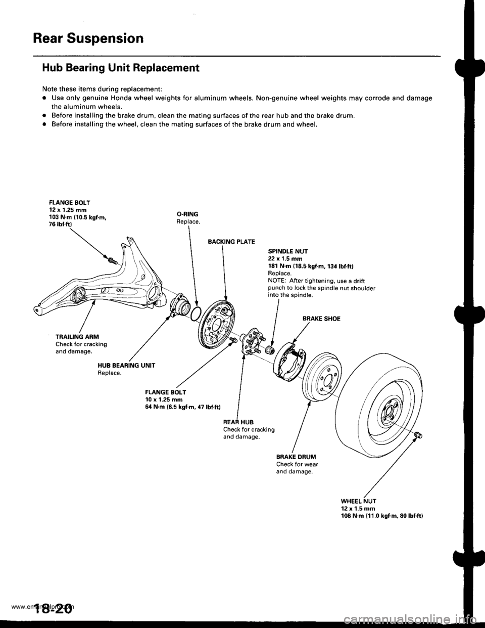
Rear Suspension
Hub Bearing Unit Replacement
Note these items during replacement:
. Use only genuine Honda wheel weights for aluminum wheels. Non-genuine wheel weights may corrode and damage
the aluminum wheels.
. Before installing the brake drum, clean the mating surfaces of the rear hub and the brake drum.
. Before installing the wheel, clean the mating surfaces of the brake drum and wheel.
FLANGE BOLI12 x 1,25 mm103 N.m 110.5 kgf.m,76 tbtfr)
BACKING PLATE
SPINDI-E NUT22 x'1.5 mm181 N.m {18.5 kgf.m, 134 lbf.ftlReplace.NOTE: Alter tightening, use a driftpunch to lock the spindle nut shoulderinto the spindle.
BRAKE SHOE
TRAILING ARMCheck {or crackingano oamage.
FLANGE BOLT10 x 1.25 mm64 N'm 16.5 kgf.m, 4? lbt.ft)
Check for crackingano oamage.
BRAKE DRUMCheck for wearano oamage,
WHEEL NUT12 x 1.5 mm108 N.m {11.0 kgt m,80lbtftl
1A-20
www.emanualpro.com
Page 920 of 1395
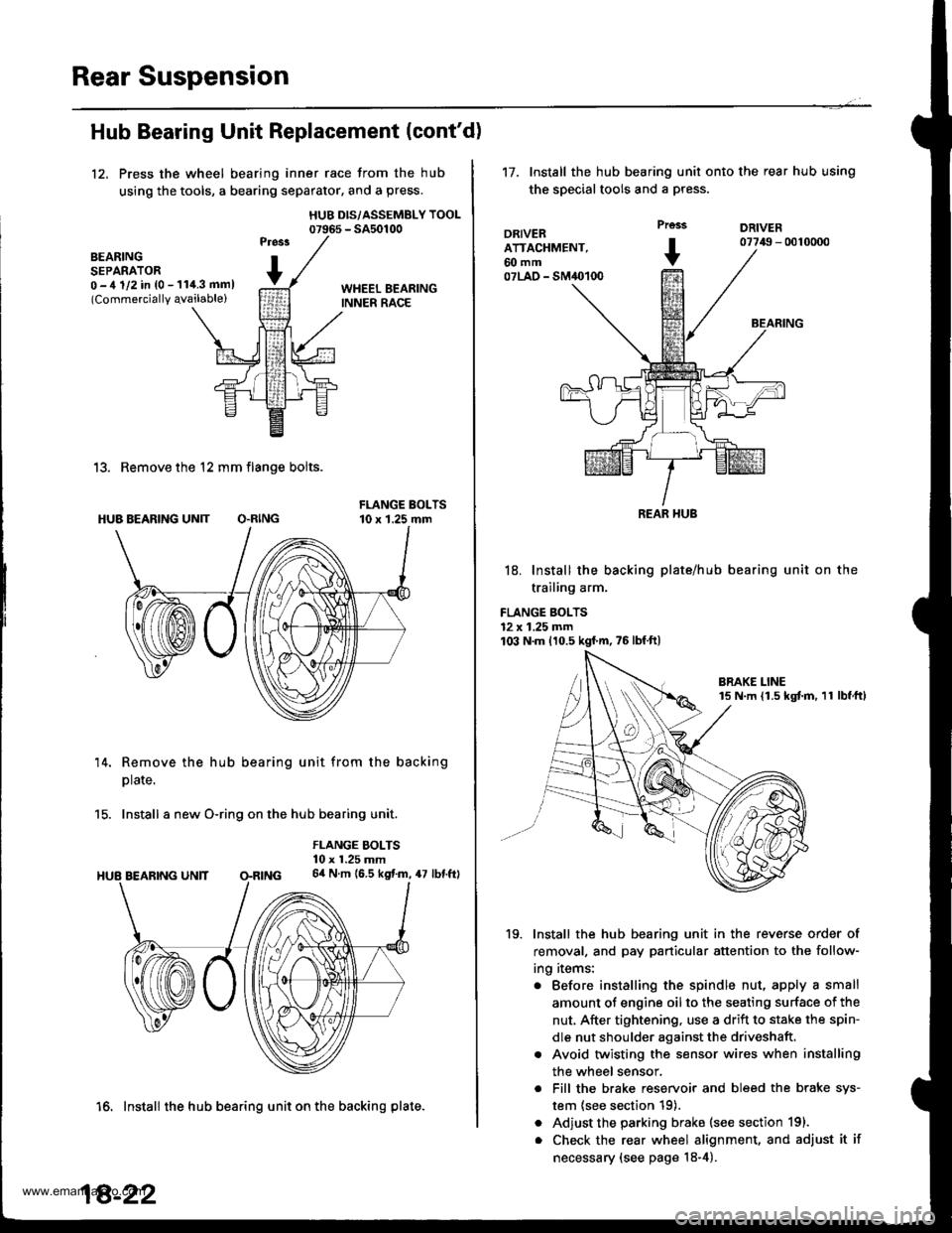
Rear Suspension
Hub Bearing Unit Replacement (cont'd)
12, Press the wheel bearing inner race from the hub
using the tools, a bearing separator, and a press.
HUB DIS/ASSEMBLY TOOL07965 - SA50100
BEARINGSEPARATOR0 -,t 1/2 in {0 - 11i1.3 mml(Commercially qvailable)
13. Remove the 12 mm flange bolts.
HUB BEARING UN]T O.RING
14. Remove the hub bearing unit from the backing
plate.
15. Install a new O-ring on the hub bearing unit.
FLANGE BOLTS10 x 1.25 mm64 N.m (6.5 kgf.m, 47 lbf.ftl
16. Install the hub bearing unit on the backing plate.
18-22
't7.Install the hub bearing unit onto the rear hub using
the special tools and a press.
DRIVERATTACHMENT,60 mm07LAO - SM40100
Prcss
+
DRIVER07749 - 0010000
BEARING
18. Install the backing plate/hub
trailing arm.
FLANGE BOLTS12 x 1.25 mm103 N.m 110.5 kgf'm,75lbfft)
bearing unit on the
19. Install the hub bearing unit in the reverse order of
removal, and pay particular attention to the follow-
ing items:
. Before installing the spindle nut, apply a small
amount of engine oil to the seating surface of the
nut, After tightening, use a drift to stake the spin-
dle nut shoulder against the driveshaft.
. Avoid twisting the sensor wires when installing
the wheel sensor,
. Fill the brake reservoir and bleed the brake sys-
tem {see section 19).
. Adjust the parking brake (see section 191.
. Check the rear wheel alignment, and adjust it if
necessary (see page 18-4).
REAR HUB
www.emanualpro.com
Page 921 of 1395
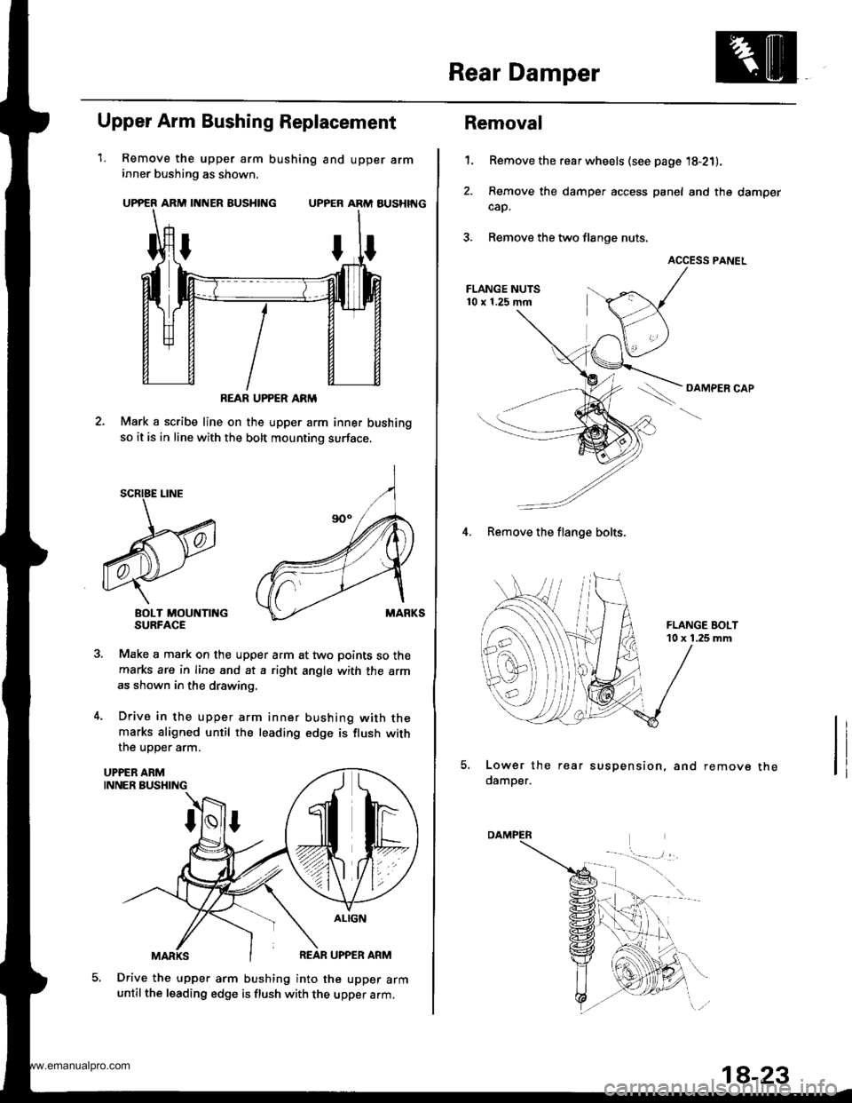
Rear Damper
1.
Upper Arm Bushing Replacement
Remove the upper arm bushing and upper arminner bushing as shown.
UPPER ARM INNER BUSHING UPPER ARM AUSHIT{G
Mark a scribe line on the upper arm inner bushing
so it is in line with the bolt mounting surface.
BOLT MOUNTII{GSURFACE
Make a mark on the upper arm at two points so the
marks are in line and at a right angle with the arm
as shown in the drawing.
Drive in the upper arm inner bushing with themarks aligned until the leading edge is flush with
the uoDer arm.
Drive the upper arm bushing into the upper armuntil the leading edge is flush with the upper arm.
REAR UPPER ARM
5.
Removal
Remove the rear wheels (see page '18-21),
Remove the damper access panel and the damper
cap.
Remove the two flange nuts.
ACCESS PANEL
OAMPER CAP
't.
4. Remove the flange bolts.
Lower the rear suspension, and remove
damper.the
1a-23
www.emanualpro.com
Page 980 of 1395
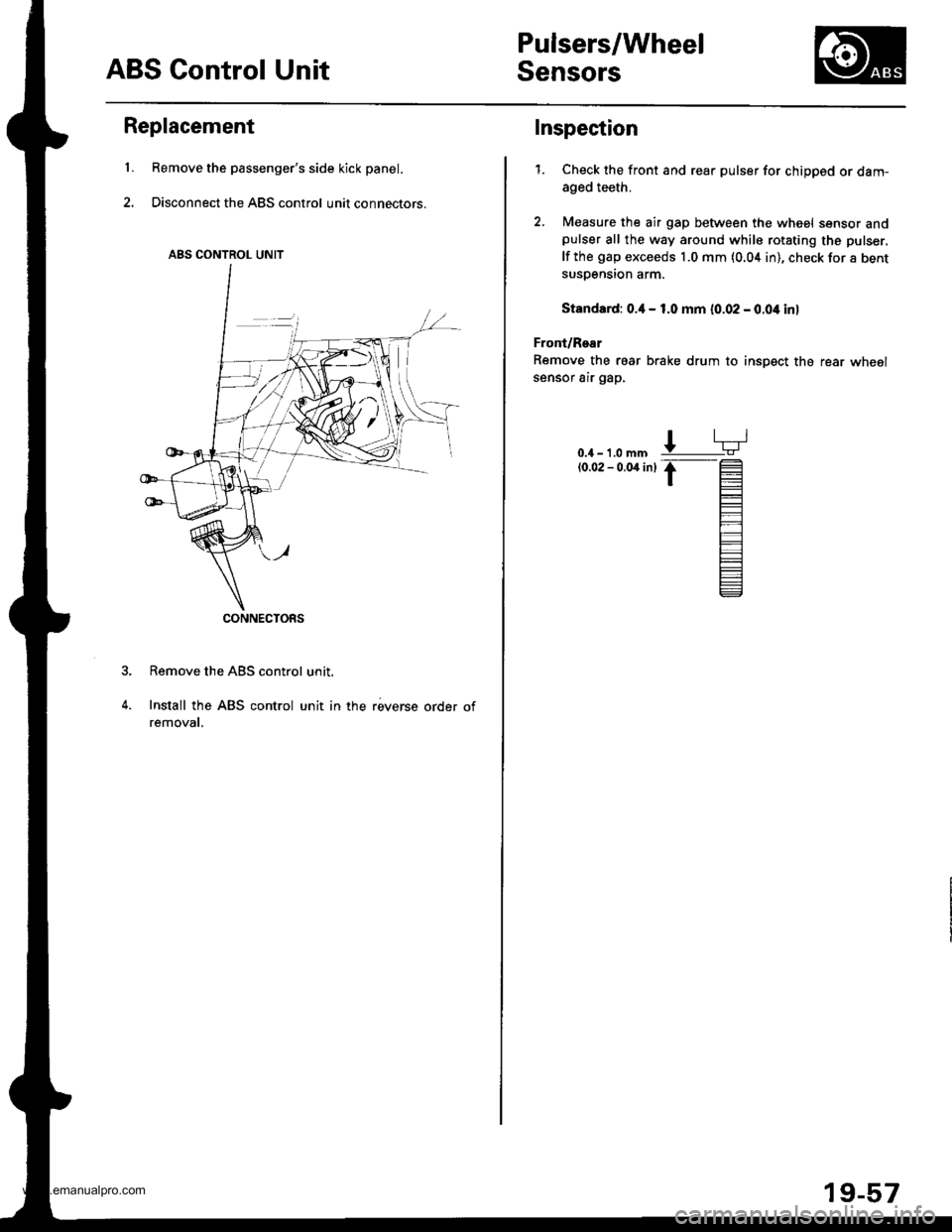
ABS Control Unit
Pulsers/Wheel
Sensors
Replacement
Remove the passenger's side kick panel.
Disconnect the ABS control unit connectors.
Remove the ABS control unit.
Install the ABS control unit in the reverse order ofremovat.
ABS CONTROL UNIT
CONNECTORS
L
Inspection
1.Check the front and rear pulser for chipped or dam-
aged teeth.
Measure the air gap between the wheel sensor andpulser all the way around while rotating the pulser.
lf the gap exceeds 1.0 mm (0.04 in), check for a bentsusDension arm.
Standard: o.il - 1.0 mm 10.02 - 0.04 inl
Front/Rear
Remove the rear brake drum to insDect the rear wheolsensor air gap,
0.4 - 1.0 mm(0.02 - 0.04 inl
19-57
www.emanualpro.com
Page 985 of 1395
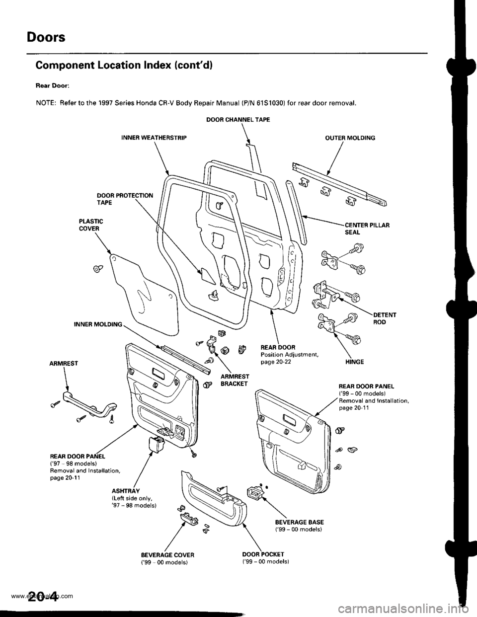
Doors
Gomponent Location Index (cont'dl
Rear Door:
NOTE: Refertothe 1997 Series Honda CR-V Bodv RepairManual (P/N 6151030) for rear door removal.
INNER WEATHERSTRIPOUTER MOLOING
DOOR PROTECTION
ARMREST
REAR DOOR('97 -98 models)
HINGE
REAR DOOR PANEL1'99 - 00 models)Removal and Installation,page 20 '11
@
ARMRESTBRACKET
Position Adiustment,page 20-22
tu4
dP
@
o
@
Bemoval and Installation,page 20-11
(Left side only,'97 - 98 models)
\
DOOR CHANNEL TAPE
FR,
)Ei
D\
\a
20-4
('99 - 00 models)
www.emanualpro.com
Page 992 of 1395
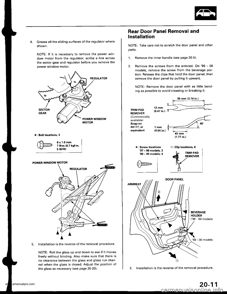
4. Grease all the sliding surfaces of the regulator where
shown.
NOTE: lf it is necessary to remove the power wrn-
dow motor from the regulator, scribe a line across
the sector gear and regulator before you remove the
power window motor.
R€GULATOF
>: Boh locations,3
6x1.0mm7 N.m lo.t kgf.m,5 tbf.ftl
POWER WINOOW MOTOR
REGULATOR
Installation is the reverse of the removal procedure.
NOTEi Rollthe glass up and down to see if it moves
freely without binding. Also make sure that there is
no clearance betlveen the glass and glass run chan
nel when the glass is closed. Adjust the position of
the glass as necessary (see page 20-20).
4
A
m^i
A
Rear Door Panel Removal and
lnstallation
NOTE: Take care not to scratch the door panel and other
parts.
1. Remove the inner handle (see page 20-5).
2. Remove the screws from the armrest. On '99 - 00
models, remove the screw from the beverage por-
tion. Release the clips that hold the door panel, then
remove the door panel by pulling it upward.
NOTE: Remove the door panel with as little bend-
ing as possible to avoid creasing or breaking it.
TBIM PADREMOVER(Commercially
available)Snap-on#4177, orequivalentlmm{0.04 in.)
>: Screw locelions'97 - 98 models. 3'99 - 00 modols, 4
11.77 in.)
DOOB PANEL
ARMREST
o
i
'99 - 00 models:
3. Installation is the reverse of the removal procedure.
\(,1
t_
T r-----/t5 mm I
EEVERAGEHOLDEN('99 00 modelsi
>i Clip locations,6
20-11
www.emanualpro.com
Page 1011 of 1395
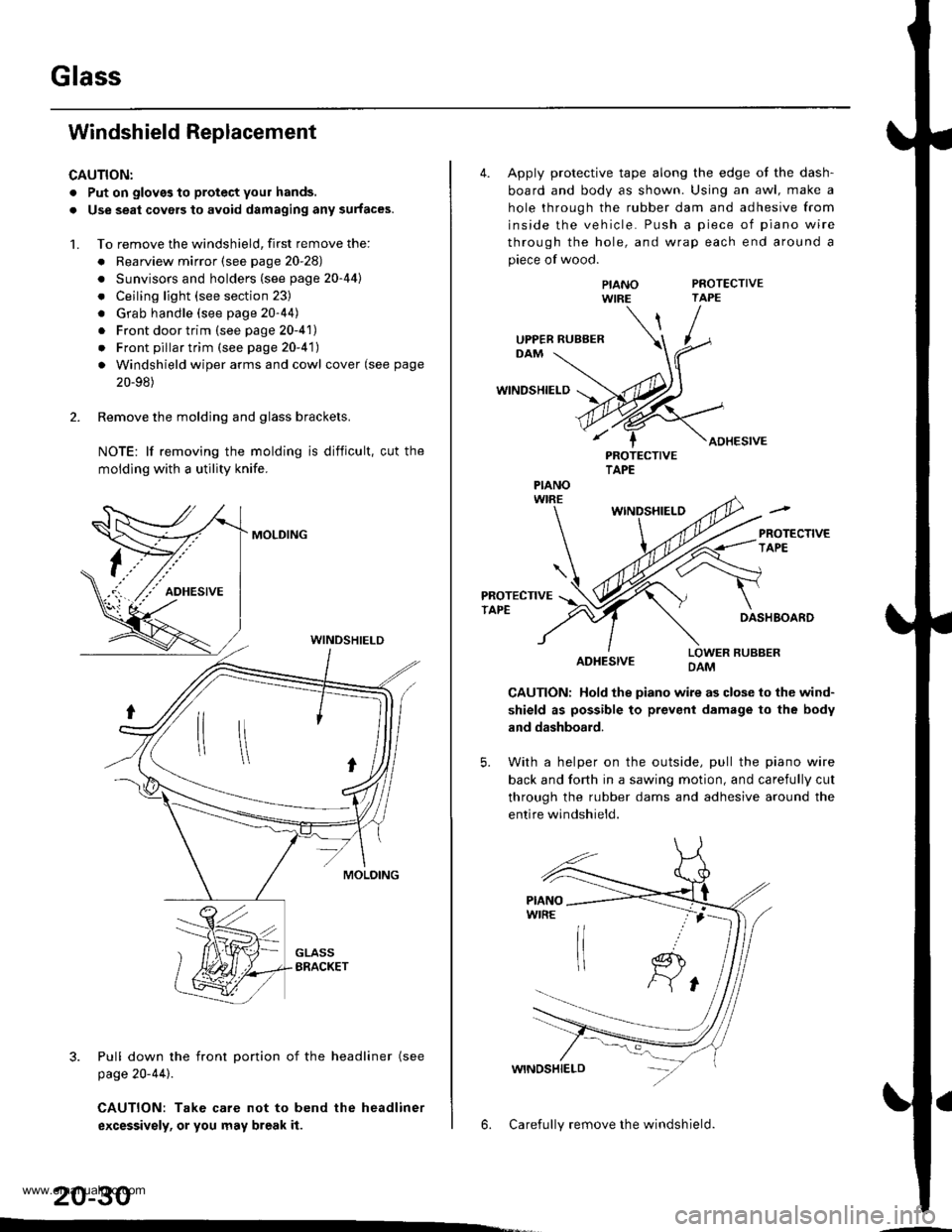
Glass
Windshield Replacement
CAUTION:
. Put on gloves to protect your hands.
. Use seat covers to avoid damaging any surfaces.
1. To remove the windshield, first remove the:
. Rearview mirror (see page 20-28)
. Sunvisors and holders (see page 20-44l'
. Ceiling light (see section 23)
. Grab handle (see page 20-44)
. Front door trim (see page 20-41)
. Front pillar trim (see page 20-41)
. Windshield wiper arms and cowl cover (see page
20-98)
2. Remove the molding and glass brackets.
NOTE: lf removing the molding is difficult, cut the
moldlng with a utility knife.
MOLDING
3. Pull down the front Dortion of the headliner (see
page 20-44).
CAUTION: Take care not to bend the headliner
excessivsly, or you may break it.
WINDSHIELD
20-30
4. Apply protective tape along the edge ot the dash-
board and body as shown. Using an awl, make a
hole through the rubber dam and adhesive from
inside the vehicle. Push a piece of piano wire
through the hole, and wrap each end around a
piece of wood.
PROTECTIVETAPE
WINDSHIELD
ADHESIVE
PIANOWIRE
PROTECTIVETAPE
WINDSHIELO
PROTECTIVETAPEDASHBOARD
ADHESIVELOWER RUBBERDAM
CAUTION: Hold the piano wire as close to the wind-
shield as possible to prevent damage to the body
and dashboard.
5. With a helper on the outside, pull the piano wire
back and fo(h in a sawing motion, and carefully cut
through the rubber dams and adhesive around the
entire windshield.
6. Carefully remove the windshield.
UPPER RUBBER
PIANO
www.emanualpro.com
Page 1037 of 1395
Seats
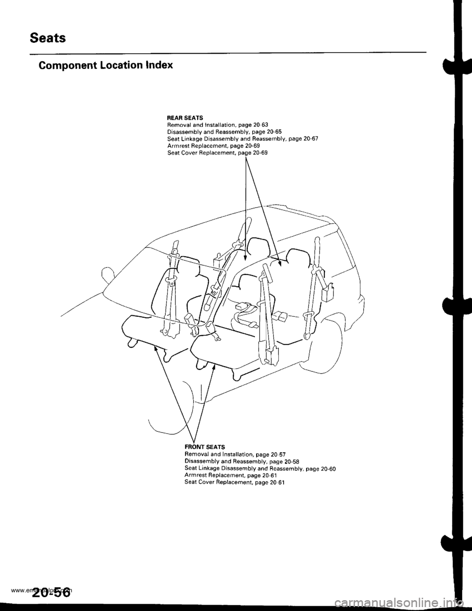
Component Location Index
REAR SEAISRemoval and lnstallation, page 20 63Disassembly and Reassembly, page 20 65Seat Linkage Disassembly and Reassembly, page 20-67Armrest Replacement, page 20-69Seat Cover Replacement, page 20-69
Removal and Installation, page 20 57Disassembly and Reassembly, page 2O-58Seat Linkage Disassembly and Reassembly, page 20-60Armrest Fleplacement, page 20 61Seat Cover Replacernent, page 20 61
20-56
www.emanualpro.com