rear arm HONDA CR-V 2000 RD1-RD3 / 1.G Owner's Manual
[x] Cancel search | Manufacturer: HONDA, Model Year: 2000, Model line: CR-V, Model: HONDA CR-V 2000 RD1-RD3 / 1.GPages: 1395, PDF Size: 35.62 MB
Page 1049 of 1395
Seats
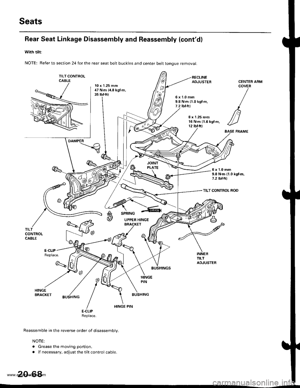
Rear Seat Linkage Disassembly and Reassembly (cont'd)
with tilt:
NOTE: Refer to section 24 for the rear seat belt buckles and center belt tongue removal
TILT CONTFOLCABLE10 x 1.25 mm47 N.m {i1.8 kgt.m,35 tbf.ft)
ARM
6x1.0mm9.8 N.m n.0 kgt.m,7.2 tbt.tll
CENTEBCOVER
/
n
//-)
ASE FRAME
8 r 1.25 mm16 N.m (1.6 kgf.m,12 tbt.ftl
DAMPER
6x1.0mm9.8 N.m 11.0 kgtm,7.2 tbttr)
TILT CONTROL ROD
A
@
SPRING
UPPER HINGE
TILTCONTROLCABLE
Replace.
q
BUSHING
E.CLIPReptace.
Reassemble in the reverse order of disassembly.
NOTE:
. Grease the moving ponion.
. lf necessary, adjust the tilt control cable.
20-64
HINGE PIN
www.emanualpro.com
Page 1050 of 1395
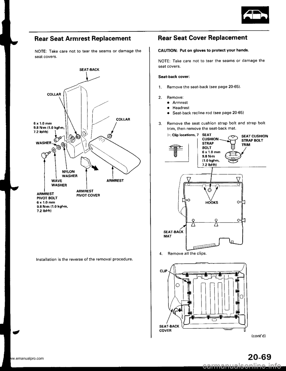
Rear Seat Armrest Replacement
NOTE: Take care not to tear the seams or damage the
seat covers.
COLLAR
COLLAR6x1.0mm9.8 N.m {1.0 kgf.m,7.2 rbr.ft)
WASHER
NYLONWASHER
VEARMRESTWASHER
ARMRESTPIVOT BOLT6x1.0mm9.8 N.m (1.0 kgt.m,7.2lbllll
lnstallation is the reverse of the removal procedure.
SEAT.BACK
Rear Seat Cover Replacement
CAUTION: Put on gloves to protect your hands.
NOTE: Take care not to tear the seams or damage the
seal covers.
Seal-back cover:
Remove the seat-back {see page 20-65).
Remove:
a Armrest
. Headrest
. Seat-back recline rod (see page 20-65)
Remove the seat cushion strap bolt and strap bolt
trim, then remove the seat-back mat.
L
2.
"'---.' t.-r" t-- i,': "" '
4. Remove all the clips.
(cont'd)
20-69
www.emanualpro.com
Page 1078 of 1395
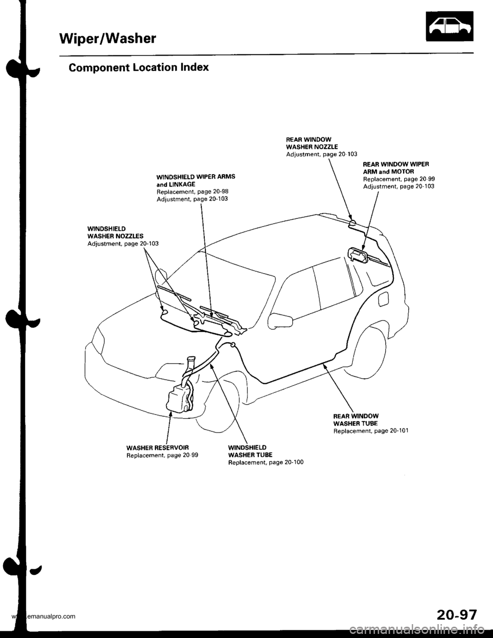
Wiper/Washer
Component Location Index
WINOSHIELD WIPER ARMS
and LINKAGEReplacement, page 20-98
Adiustment, Page 20-103
REAR WINDOW WIPERARM and MOTORReplacement, page 20 99Adiustment, page 20 103
WASHER RESERVOINReplacement, page 20 99WASHER TUBEReplacement, page 20-100
20-97
www.emanualpro.com
Page 1080 of 1395
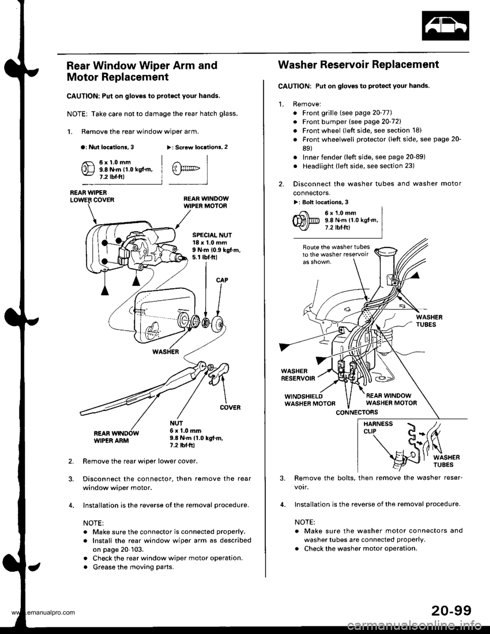
Rear Window Wiper Arm and
Motor Replacement
CAUTION: Put on gloves to protect your hands.
NOTE; Take care not to damage the rear hatch glass.
1. Remove the rear window wiper arm.
a: Nut loc.tion!, 3>: Scaow locationa, 2
REAR WINDOWWIPER MOIOR
REAR WIPERCOVER
REARWIPER ARM
6x1.0mm9.8 N.m 11.0 kgt'm,7.2 tbf.ftl
SPECIAL NUT18 x 1.0 mm9 N.m 10.9 kgt m,5. r tbt.ftl
NUT6x 1.0mm9.8 N.m {1.0 kgt.m,?.2 tbfftl
Remove the rear wiper lower cover.
Disconnect the connector, then remove the rear
window wiper motor.
Installation is the reverse of the removal procedure.
NOTE:
. Make sure the connector is connected properly.
. Install the rea. window wiper arm as described
on page 20-103.
. Check the rear window wiper motor operation.
. Grease the moving parts.
@rrc
Washer Reservoir Replacement
GAUTION: Put on gloves to protect your hands.
1. Remove:
. Front grille (see page 20-771
. Front bumper (see page 20-721
. Front wheel {left side, see section 18)
. Front wheelwell protector (left side, see page 20-
89)
. Inner fender (left side, see page 20-89)
. Headlight (left side, see section 23)
2. Disconnect the washer tubes and washer motor
connectors.
>: Bolt locations, 3
6x1.0mm9,8 N.m 11.0 kgt.m,7.2 tbt.ftl
Route the washer tubesto the washer teservoir
WASHERRESERVOIR
WINOSHIELOWASHER MOTON
CONNECTORS
3. Remove the bolts, then remove the washer reser-
votr,
4. Installation is the reverse of the removal procedure.
NOTE:
a Make sure the washer motor connectors and
washer tubes are connected properly.
. Check the washer motor operation.
HARNESS / tcLrP C-(fu
- S(ilq
s{J
l' wrsHER
20-99
www.emanualpro.com
Page 1084 of 1395
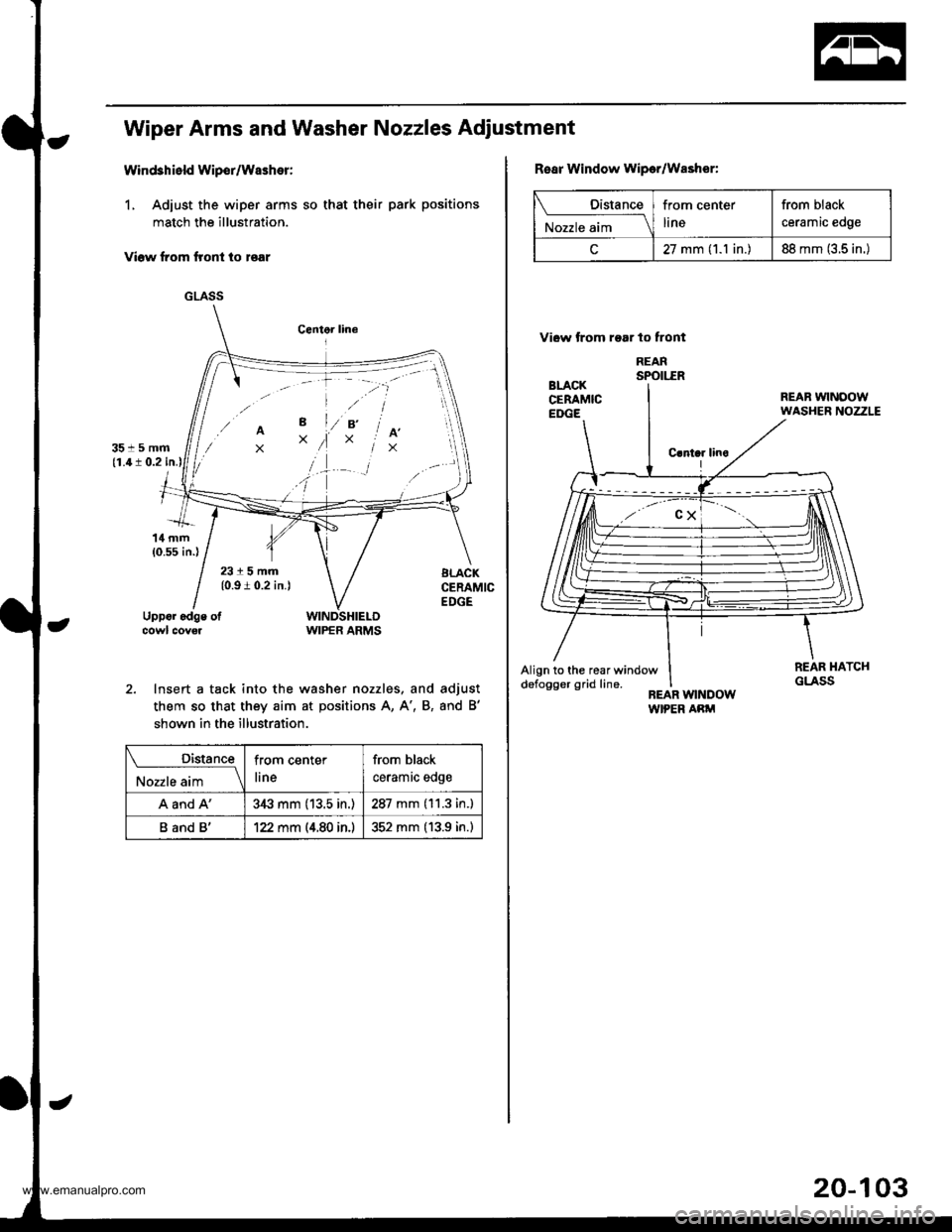
Wiper Arms and Washer Nozzles Adiustmenl
Wind3hield Wipor/Washer:
1, Adiust the wiper arms so that their park positions
match the illustration.
Viow from flont io roar
GLASS
2. Insert a tack into the washer nozzles. and
them so that they aim at positions A, A', B,
shown in the illustration.
adjust
and B'
Distance
^,J;-ll\
from center
line
from black
ceramic edge
A and A'3,$ mm (13.5 in.)287 mm (11.3 in.)
B and B'122 mm (4.80 in.)352 mm (13.9 in.)
Rear Window wipor/Washer:
Vi6w trom roar to lront
REARsPo[.-ER
C.nlar linoL
Align to the rear windowdefogger grid line.
Distance
ru"rrr. "i.
'_\from center
ltne
from black
ceramic edge
27 mm (1.1 in.)88 mm (3.5 in.)
20-103
www.emanualpro.com
Page 1089 of 1395
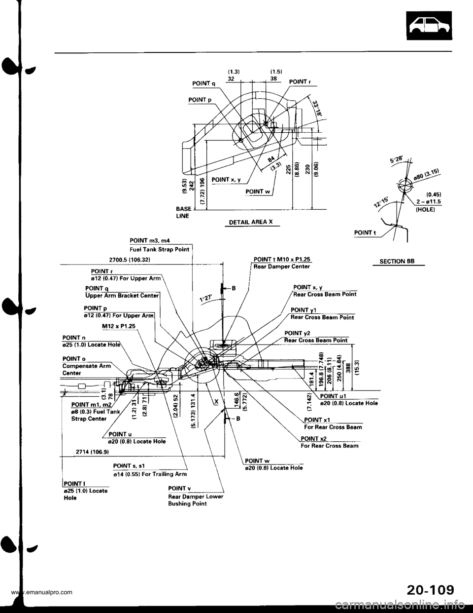
POlNTx.y / I
'sad
POINT m3, m4
Upper Arm
M12 x P1.25
Locate Hole
POINT 3, s1
o14 {0.551 For Trailing Aim
POINT v
Fuel Tank Strap Poinr
2700.5 (106.32)SECTION BBRear Damoer Center
POINT n
FOINT
rg (0.3) Fuel TStrap Center
271,1(10,6.9)
o2010.8| Locate Hole
For Rear Cros3 Beam
For Reer Cross Beam
POINT w
Bear Damper LowerBushing Point
I
\-
ql
ol
.df
20-109
www.emanualpro.com
Page 1180 of 1395

Connector ldentification and Wire Harness Routing
Main Wire Harn€ss (left side of dash and floor branchesl {cont,dl
c401
c402
c403
c404
c404
c405
c406
c407
c408
c409
c410
c410
c411
c412
c413
c413
c414
c415
c416
c416
c417
c418
c419
c420
c420
c421
c422
c423
c424
c425
c42A
c426
c437
c438
c438
c439
c440
c441c442
5
20
20
24
't4
8
5
3
12
10'1
18
20'18
10
15
1
4
8
5
5
22
Behind left kick panel
Behind left kick panel
Behind left kick panel
Behind left kick panel
Behind left kick panel
Under left side of dashUnder left side of dashUnder left side of dashUnder left side of dashUnder left side of dashUnder left side of dashUnder left side of dash
Under left side of dashUnder left side of dashUnder left side of dash
Under left side of dash
Under left side of dashUnder left side of dashUnder left side of dashUnder left side of dashUnder left side of dashUnder left side of dashUnder left side of dashUnder left side of dash
Under left side of dashUnder left side of dashUnder left side of dashUnder middle of dashUnder middle of dashUnder middle of dashUnder middle of dashUnder middle of dash
Under left side of dashUnder left side of dash
Under left side of dashUnder left side of dashUnder left side of dashUnder left side of dashUnder left side of dash
Under left side of dash
Under left side of dashUnder left side of dashUnder left side of dashUnder left side of dash
Starter cut relay
Horn relay
Left side wire harness (C558)
Left side wire harness (C559)
Left side wire harness (C559)
Cruise control unitDaytime running lights control unitDaytime running lights control unitlgnition key light control unitInterior wire harness {C701)Cable reel
Cable reel
lgnition key switchlgnition key switch
Combination switch sub-harness {C753)
Combination switch sub-harness (C753)
SRS main harness (C803)
Dashboard wire harness (C503)
Dashboard wire harness (C501)
Dashboard wire harness {C501)Under-dash fuse/relay box (C922)
Under-dash fuse/relay box (C920)
Under-dash fuse/relay box (C919)
lntegrated control unit
Integrated control unitFront fog lights switchBrake switch
Interlock control unitReverse relay
Rear accessory socket relayRear accessory socket relayRear heated oxygen sensor sub-harness (C722)
Security control unitSecurity starter cut relay (for securityalarm system)
Junction connector (for interlock system)Security wire harnessSecurity wire harnessRear window wiper control unitCombination switch sub-harness (C760)
Combination switch sub-harness (C760)
Securlty indicatorSecurity valet switchClutch interlock switchClutch switch (for cruise control)
'97 model'98 - 00mooets
Canada
Canada'97 model
'97 model'98 - 00models
'97 - 98models'99 - 00
moqets
'97 model'98 - 00mooets
Optional
Optional
Optional
Optional
Optional'97 model
'97 - 98mooels'99 - 00models
OptionalOptional
Mfi
Mlr
Under left side of dashBody ground, via main wire harness
23-20
www.emanualpro.com
Page 1186 of 1395

Connector ldentification and Wire Harness Routing
Left Side Wire Harness
Connector oI
Terminal
Number of
CavitiesLocaiionConnects toNot6s
c551
c552
c554
c556
c558
c559
c559
c560
c562
c563
c563
c564
c565
c566
c568
c569
c570
c572
c573
c57 4
c575
c576
c578
c579
c580
c581
8
16
10
14'I
14
16
20
20
24
)
1
5
1
1
6
1
2
14
1
1
6
1
6
Behind under-dash fuse/relay box
Behind under-dash fuse/relay box
Left side of steering wheel
Left side of steering wheel
Left side of steering wheel
Above under-dash fuse/relay box
Above under-dash fuse/relay box
Driver's door
Behind left kick panel
Behind left kick panel
Behind left kick panel
Left side offloor
Left quaner panel
Fueltank
On left half of rear cross beam
On left half of rear cross beam
Left quarter panel
Left quarter panel
Left quarter panel
Left quarter panel
Left quarter panel
Left quarter panel
On left half of rear cross beam
Right quarter panel
Right quarter panel
Left quarter pillar
Left side of floor
Left B-piller
Left B-piller
Behind left kick panel
Behind left kick panel
Under left side of dash
Left B-piller
Fueltank
Left side of steering wheel
Under-dash fuse/relay box (C921)
Under-dash fuse/relay box (C923)
Power mirror switch
Power window master switch
Power window master switch
Dashboard wire harness {C505)
Dashboard wire harness 1C505)
Driver's door wire harness (C661)
Main wire harness (C403)
Main wire harness (C404)
Main wire harness (C404)
Driver's seat belt switch
Left rear door switch
Fuel unit
Left rear ABS wheel sensor
Left rear ABS wheel sensor
Rear accessory socket connector {+}
Rear accessory socket connector (-)
Rear bumper wire harness 1C641)
Trailer lighting connector
Tailgate door latch switch
Left rear speaker
Right rear ABS wheel sensor
Rear wire harness (C611)
Right rea. door switch
Left taillight
Parking brake switch
Left rear door wire harness (C681)
Driver's door switch
Select unlock relay (for security alarm
system)
Junction connector (for power door
locks)
SRS main harness (C807)
Driver's seat belt tensioner
Fuel tank pressure sensor sub-harness(c645)
Power window master switch
'97 - 98
mooets'99 - 00
models
'97 model'98 - 00
models
Optional
'97 model'98 - 00
models
'98 - 00
mooets'98 - 00
models'98 - 00
mooets'99 - 00
mooets
G551
G553
Behind left kick panel
Left side ot floor
Left quarter piller
Body ground, via left side wire harness
Body ground, via left side wire harness
Body ground, via left side wire harness
23-26
www.emanualpro.com
Page 1279 of 1395
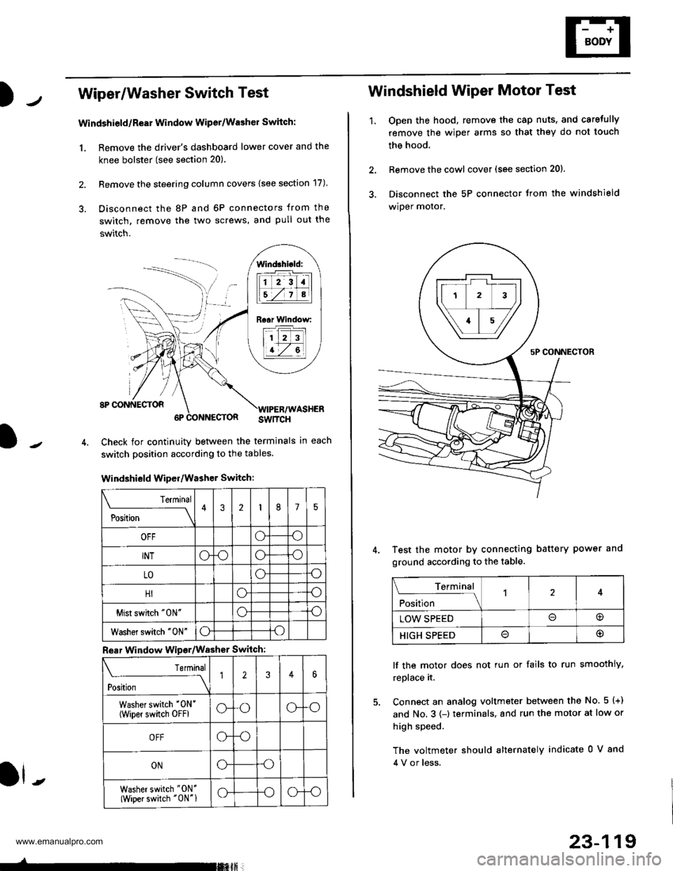
Wiper/Washer Switch Test
Windshield/ReEr Window Wiper/Washer Switch:
1. Remove the driver's dashboard lower cover and the
knee bolster (see section 20).
2. Remove the steering column covers {see section 17)
3. Disconnect the 8P and 6P connectors from the
switch, remove the two screws, and pull out the
switch.
J-
lind3hi.ld:
tilt-rltl
IEZIA
Raar Window:
11 2 3
I t-7 al
ll -
Check for continuity betlveen the termlnals in each
switch position according to the tables.
Windshield Wiper/Washer Switch:
Terminal
P*t-
---__\432175
OFFoo
INToooo
LOoo
HIoo
Mist swhch "0N"oo
Washer switch "0N"oo
Rear Window Wipsr/Washer Switch
Teminal
ti'"
---\12346
Washer switch '0N'
(wiper switch oFFlG-oG-o
OFFG-o
ONGo
Washer switch "ON'
(Wiper switch "0N"1G-oG-o
-rmxft
23-119
1.
Windshield Wiper Motor Test
Open the hood, remove the cap nuts, and caretully
remove the wiper arms so that they do not touch
the hood.
Remove the cowl cover (see section 201.
Disconnect the 5P connector trom the windshield
wiper motor.
Test the motor by connecting battery power and
ground according to the table.
lf the motor does not tun or fails to run smoothly,
replace it.
Connect an analog voltmeter between the No. 5 (+)
and No. 3 (-) terminals, and run the motor at low or
high speed.
The voltmeter should alternately indicate 0 V 8nd
4 V or less.
Terminal
;fi;"
-l4
LOW SPEED@
HIGH SPEED@
www.emanualpro.com