body HONDA CR-V 2000 RD1-RD3 / 1.G Workshop Manual
[x] Cancel search | Manufacturer: HONDA, Model Year: 2000, Model line: CR-V, Model: HONDA CR-V 2000 RD1-RD3 / 1.GPages: 1395, PDF Size: 35.62 MB
Page 1129 of 1395
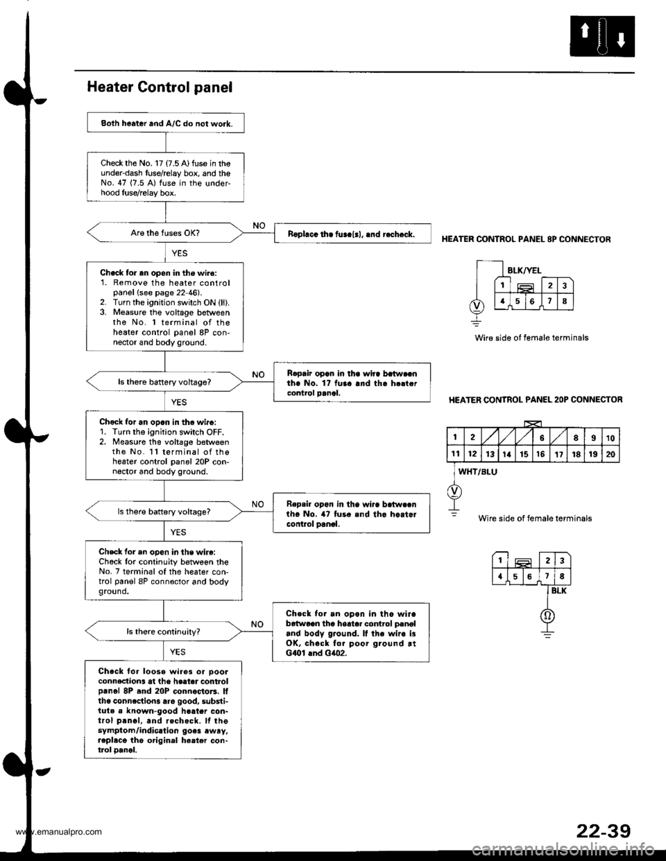
Both heater and A/C do not work.
Check the No. 17 (7.5 A)fuse in theunder-dash fuse/relay box, and theNo. 47 (7.5 A) fuse in the under-hood luse/relay box.
nophcc ih. fur.l.l, .nd r.check.
Check tor rn open in the wiro:1. Remove the heater controlpanellsee page 22 46).2. Turn the ignition switch ON (ll).3. Measure the voltage betweenthe No. 1 terminal of theheater control panel 8P con-nector and body ground.
R.pair opan in lha wlra batw.cnthe No. 1? fuaa and tha h.ltcrcontrol panal.ls thero battery voltage?
Chgck for an opan in th€ wirg:1. Turn the ignition switch OFF.2. Measure the voltage betweenthe No. l l terminal of thoheater control panel 20P con-noctor and body ground.
Repsil opon in tha wi.a batwcanth. No. 47 tur. and tho hoitorcontlol panol.
ls there battery voltags?
Check for an opon in the wire:Ch6ck lor continuity betwoen theNo. 7 terminal of the heater con-trol panel 8P connector and bodyground.
Check for an opon in tho wirab6{woon tho hoatar control p.noland body ground. It the wir. i3OK, chsck for poor ground rtGlOl lnd Glo2.
Check for loose wire3 or oooaconnection3 at the haater controlprnol 8P and 20P connoctors. Itthc conncction3 are good, substi-tuta a known-good h€ater con-trol prnol, and rechecft. lf thesymptom/indic.lion go.3 ewry,repl.cg the original ha.ter con-tlol oancl.
HEATER CONTROL PANEL 8P CONNECTOR
Wire side ot female terminals
HEATER CONTROL PANEL 2OP CONNECTOR
I2A,/1,/58910
1t12131a151517181920
WHT/BLU
Wire side of female terminals
23
{578
BLK
0
www.emanualpro.com
Page 1134 of 1395
Evaporator Temperature
SensorPower Transistor
Test
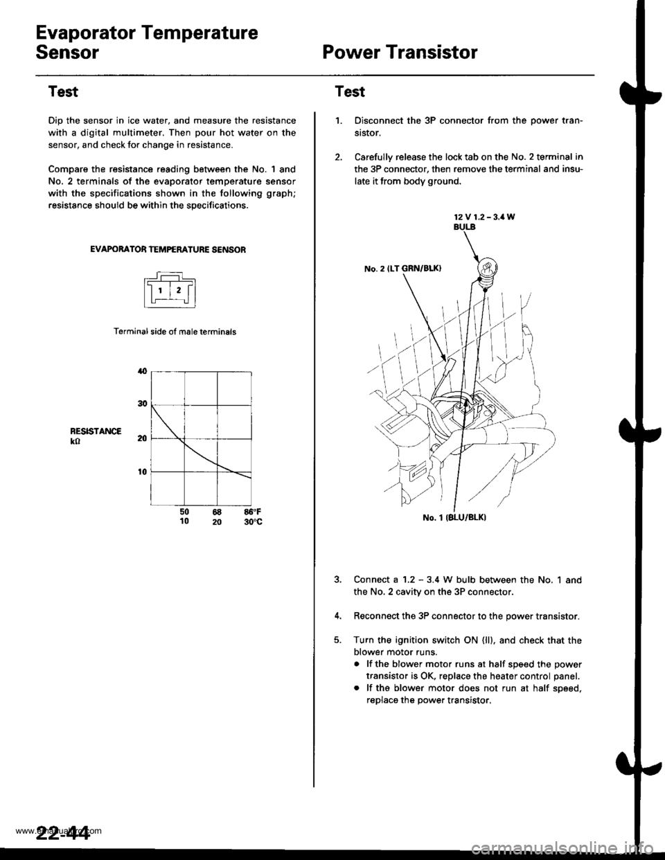
Dip the sensor in ice water, and measure the resistance
with a digital multimeter. Then pour hot water on the
sensor, and check lor change in resistance.
Compare the resistance reading between the No. | 8nd
No. 2 terminals of the evaporator temperature sensor
with the specifications shown in the following graph;
resistance should be within the specifications.
EVAPOBATOR TEMPERATURE SENSOB
Terminal side ol male terminals
4
RESISTANCEko
t0
50 68 86.F10 20 30'c
22-44
12V 1.2-3.1W
No. 2 ILT GRN/BLK)
No. I IBLU/BLK)
Test
1.Disconnect the 3P connector from the oower tran-
st$or.
Carefully release the lock tab on the No. 2 terminal in
the 3P connector, then remove the terminal and insu-
late it from body ground.
Connect a 1.2 - 3.4 W bulb between the No, 1 and
the No,2 cavity on the 3P connectol
Reconnect the 3P connector to the power transistor.
Turn the ignition switch ON (ll). and check that the
blower motor runs.
a lf the blower motor runs at half soeed the oower
transistor is OK, replace the heater control panel.
. lf ths blower motor does not run at half soeed,
reDlaca the Dower transistor.
www.emanualpro.com
Page 1161 of 1395

Body Electrical
Speciaf Toofs ,...,..,.............-.23-2
Troubleshooting
Tips and Precautions ......,.,..........,.................. 23-3
Five-step Troubleshooting ........,.,.,...,,.,......... 23-5
Wire Color Codes ...,....,.. 23-5
Relay and Control Unit Locations
Engine Compartment ..,.,......,......................... 23-6
Dashboard ,.,.,..............-.- 23-7
Door ....................... .........23-10
Index to Cilcuits and Sysiems
Accessory Socket .. ,....,.,..,.,. 23-95*Airbags ................ .,....,. Sestion 24
Air Conditioning ,.,.,.... Section 22
Alternator ................... Section 4
Anti-lock Brake System {ABSI ................... Section 19'A/T Gear Position Indicator ....................... Section 1,1
Automatic Transmission System ...........,.. Section 14
Battery ................... ..............23-50
Blower Controls .,...,.,, Section 22
Charging System ....... Seqtion il
Clock -'98 Model ................ 23-98
Connector ldentification and Wire HarnessRouting .................. ......... 23.11
Cruise Control ............ Ssction 4
Dash Lights Brightness Contlo||er ..................... 23-90
Fan Conlrols ...,......,.... Section 10
Fuel Pump ,..,.,...,....,.... Section 11
Fuses...................... .,,.,.,.,.,,.,23-40*Gauges
Circuit Diagram ......-....-..23-58
Fuel Gauge .....,.,..... Section 11
Speedometer ..,..........,... 23-56
Ground Distribution ,....,.,...23-46
Hatch Glsss ODenor .........................,.,.,.,.,..,.,.,.,,. 23-121
Heater Controls .-........ Soction 21*Horns.,...,..,.,.,....... ................23"104*fgnition Switch ,,.,.,..,.,.,,.,.,.,23-51
lgnition Key Light System -'97 Mod6l .............. 23.88
-+
BODY
www.emanualpro.com
Page 1163 of 1395
Troubleshooting
Tips and Precautions
Bef ore Troubleshootin g
. Check applicable fuses in the appropriate fuse/relay
box.
. Check the battery for damage, state of charge, and
clean. and tight connections.
. Check the alternator belt tension.
CAUTION:
. Do not quick-charge a battery unless the battery
ground cable has been disconnected, otherwise you
will damage the alternator diodes.
. Do not attempt to crank thc engins wilh the battery
ground cable loosely connected or you will severely
damage the wiring.
Handling Connestors
. Make sure the connectors are clean and have no loose
wire terminals,
. N4ake sure multiple cavity connectors are packed with
grease (except water-tight connectors).
. All connectors have push-down release type locks.
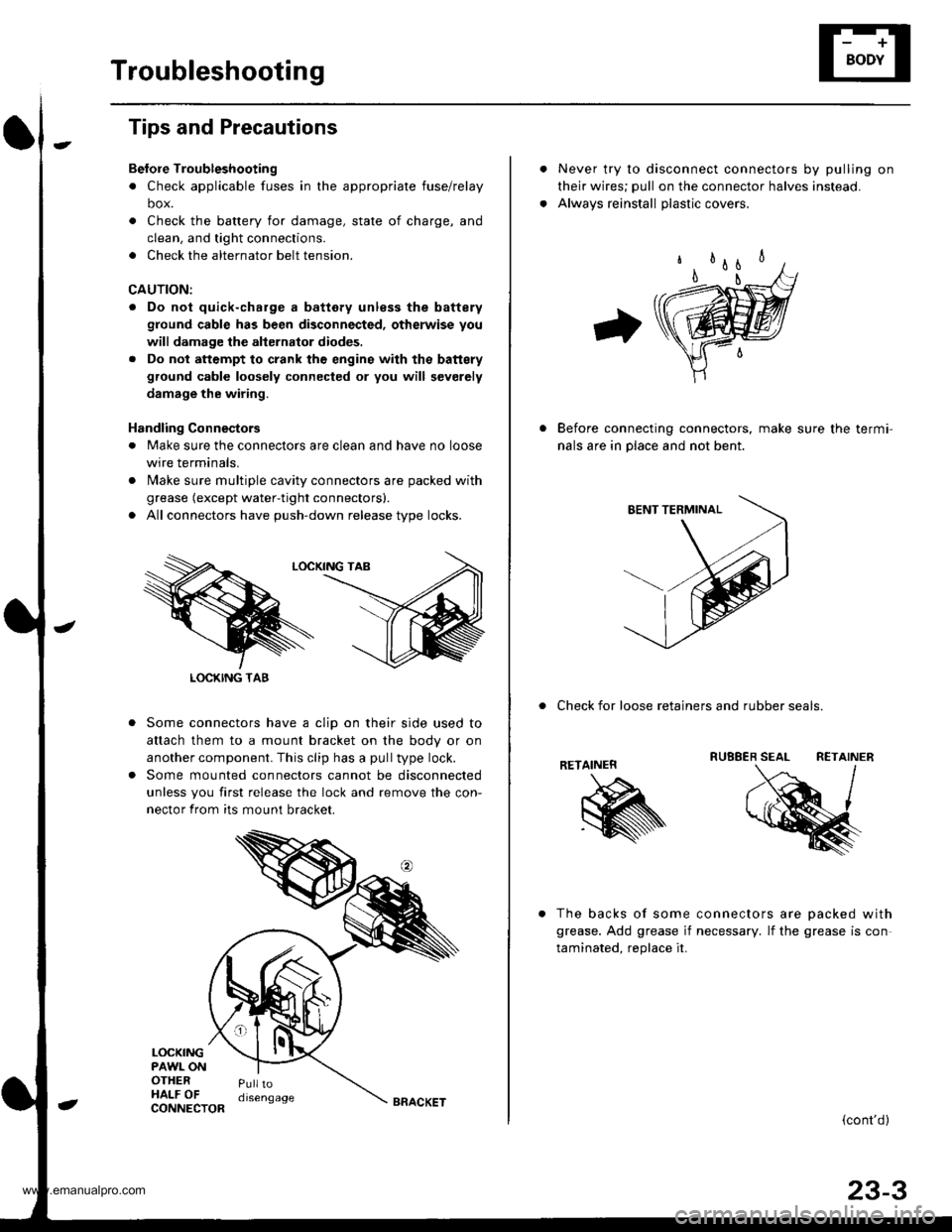
Some connectors have a clip on their side used to
attach them to a mount bracket on the body or on
another component. This clip has a pull type lock.
Some mounted connectors cannot be disconnected
unless you first release the lock and remove the con-
nector from its mount bracket.
LOCKINGPAWL ONOTHERHALF OFPulltodisengage
LOCKING TAB
CONNECTORBRACKET
Never try to disconnect connectors by pulling on
their wires; pull on the connector halves instead.
Alwavs reinstall olastic covers.
Before connecting connectors, make sure the termi-
nals are in place and not bent.
. Check for loose retainers and rubber seals.
RETAINER
The backs of some connectors are oacked with
grease. Add grease if necessary. lf the grease is con
taminated. reolace it.
{cont'd}
23-3
www.emanualpro.com
Page 1172 of 1395
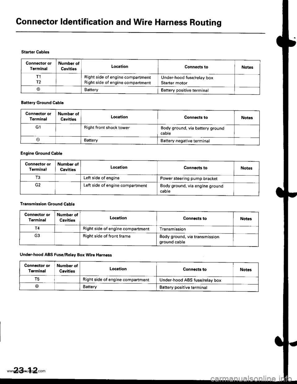
Connector ldentification and Wire Harness Routing
Connoctor or
Terminal
Number of
CavitiesLocationConnects toNotes
T1
r2
Right side of engine compartment
Right side of engine compartment
Under-hood fuse/relay box
Starter motor
oBatteryBattery positive terminal
Starter Cables
Battery Ground Cable
Connoctor or
Terminal
Number of
CavitiesLocationConneqts loNotes
GIRight front shock towerBody ground, via battery ground
cable
BatteryBattery negative terminal
Engine Ground Cable
Connector or
Terminal
Numb6r ol
CavitiesLocationConnects toNotes
T3Left side of enginePower steering pump bracket
Left side of engine compartmentBody ground. via engine ground
caote
Transmission Ground Cable
Connsstor o.
Terminal
Number of
CavitiesLocationConnects toNotes
T4Right side of engine compartmentTransmission
Right side of front frameBody ground, via transmissionground cable
Under-hood ABS Fuse/Relay Box Wire Harnsss
Conn6stor or
Terminal
Number of
CavitiesLocationConnocts toNotos
tcRight side of engine compartmentUnder-hood ABS tuse/relav box
@Battery88ttery positive terminal
23-12
www.emanualpro.com
Page 1176 of 1395
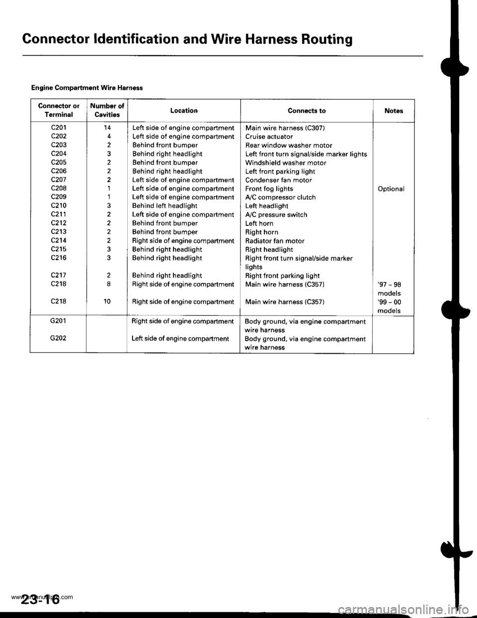
Gonnector ldentification and Wire Harness Routing
Engine Compartment Wire Harness
Connector ol
Terminal
Number of
CavitiesLocationConnects toNotes
c20'l
c202
c203
c204
c205
c206
c207
c208
c209
c210
c212
c213
c2't4
c215
c216
c217
c21A
c218
14
2
2
1'l
2
10
Left side of engine compartment
Left side of engine compartment
Behind front bumper
Behind right headlight
Behind front bumper
Behind right headlight
Left side of engine compartment
Left side of engine compartment
Left side of engine compartment
Behind left headlight
Left side of engine compartment
Behind front bumper
Behind front bumper
Right side of engine compartment
Behind right headlight
Behind right headlight
Behind right headlight
Right side of engine compartment
Right side of engine compadment
Main wire harness (C307)
Cruise actuator
Rear window washer motor
Left front turn signal/side marker lights
Windshield washer motor
Left front parking light
Condenser fan motor
Front fog lights
IVC compressor clutch
Left headlight
IVC pressure switch
Left horn
Right horn
Radiator fan motor
Right headlight
Right front turn signal/side marker
lights
Right front parking light
Main wire harness 1C357)
Main wire harness (C357)
Optional
'97 - 98
models'99 - 00
mooets
G201
G202
Right side of engine companment
Left side of engine compartment
Body ground, via engine compartment
wire harness
Body ground, via engine compartment
wire harness
23-16
www.emanualpro.com
Page 1178 of 1395
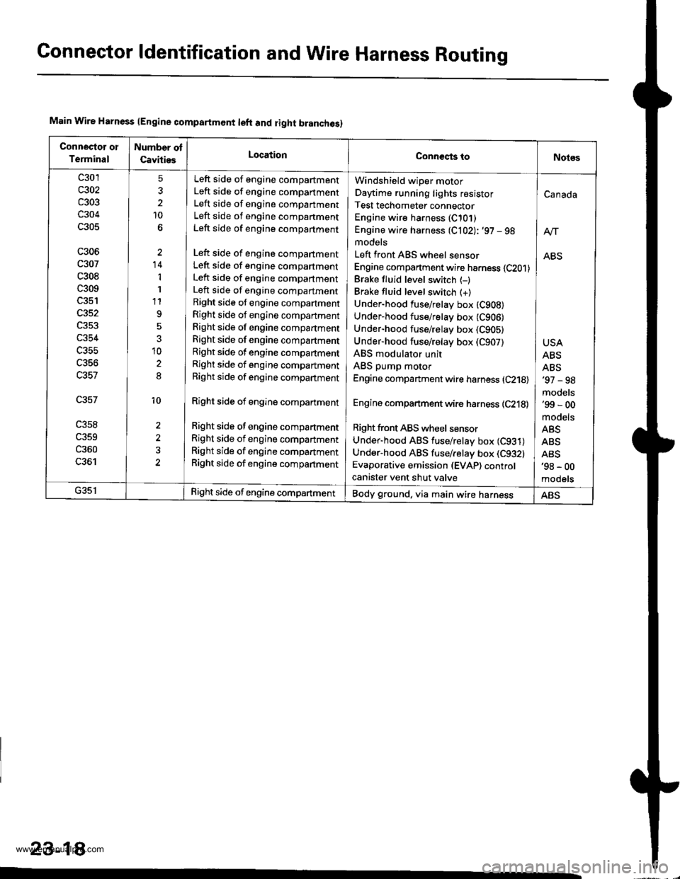
Gonnector ldentification and WireHarness Routing
Main Wire Harness lEngine compartmont left and right branches)
Connectot ol
Terminal
Number ot
CavitiesLocationConneqts toNot€s
c301
c303
c304
c305
c306
c307
c308
c309
c352
c354
c356
c357
c358
c359
c360
LJO I
5
2
10
'14
1
1
t1
3
10
8
10
2
Left side of engine compartment
Left side of engine compartment
Left side of engine compartment
Left side of engine companment
Left side of engine compartment
Left side of engine compartment
Left side of engine compartment
Left side of engine compartment
Left side of engine compartment
Right side of engine compartment
Right side of engine compartment
Right side of engine compartment
Right side of engine compartment
Right side of engine compartment
Right side of engine compartment
Right side of engine compartment
Right side of engine compartment
Right side of engine compartment
Right side of engine compartment
Right side of engine compartment
Right side of engine compartment
Windshield wiper motor
Daytime running lights resistor
Test techometer connector
Engine wire harness (C10])
Engine wire harness (C102): '97 - 98models
Left front ABS wheel sensor
Engine compartment wire harness (C201)
Brake fluid level switch {-)Brake fluid level switch (+)
Under-hood fuse/relay box (C908)
Under-hood fuse/relay box (C906)
Under-hood fuse/relay box (C905)
Under-hood fuse/relay box (C907)
ABS modulator unit
ABS pump motor
Engine compartment wire harness (C218)
Engine compartment wire harness (C218)
Right front ABS wheel sensor
Under-hood ABS fuse/retay box (C931)
Under-hood ABS fuse/relay box (C9321
Evaporative emission (EVAP) controcanister vent shut valve
Canada
ABS
USA
ABS
ABS'97 - 98
models'99 - 00
mooets
ABS
ABS
ABS'98 - 00
mooets
G35lRight side of engine compartmentBody ground, via main wire harnessABS
23-18
www.emanualpro.com
Page 1180 of 1395

Connector ldentification and Wire Harness Routing
Main Wire Harn€ss (left side of dash and floor branchesl {cont,dl
c401
c402
c403
c404
c404
c405
c406
c407
c408
c409
c410
c410
c411
c412
c413
c413
c414
c415
c416
c416
c417
c418
c419
c420
c420
c421
c422
c423
c424
c425
c42A
c426
c437
c438
c438
c439
c440
c441c442
5
20
20
24
't4
8
5
3
12
10'1
18
20'18
10
15
1
4
8
5
5
22
Behind left kick panel
Behind left kick panel
Behind left kick panel
Behind left kick panel
Behind left kick panel
Under left side of dashUnder left side of dashUnder left side of dashUnder left side of dashUnder left side of dashUnder left side of dashUnder left side of dash
Under left side of dashUnder left side of dashUnder left side of dash
Under left side of dash
Under left side of dashUnder left side of dashUnder left side of dashUnder left side of dashUnder left side of dashUnder left side of dashUnder left side of dashUnder left side of dash
Under left side of dashUnder left side of dashUnder left side of dashUnder middle of dashUnder middle of dashUnder middle of dashUnder middle of dashUnder middle of dash
Under left side of dashUnder left side of dash
Under left side of dashUnder left side of dashUnder left side of dashUnder left side of dashUnder left side of dash
Under left side of dash
Under left side of dashUnder left side of dashUnder left side of dashUnder left side of dash
Starter cut relay
Horn relay
Left side wire harness (C558)
Left side wire harness (C559)
Left side wire harness (C559)
Cruise control unitDaytime running lights control unitDaytime running lights control unitlgnition key light control unitInterior wire harness {C701)Cable reel
Cable reel
lgnition key switchlgnition key switch
Combination switch sub-harness {C753)
Combination switch sub-harness (C753)
SRS main harness (C803)
Dashboard wire harness (C503)
Dashboard wire harness (C501)
Dashboard wire harness {C501)Under-dash fuse/relay box (C922)
Under-dash fuse/relay box (C920)
Under-dash fuse/relay box (C919)
lntegrated control unit
Integrated control unitFront fog lights switchBrake switch
Interlock control unitReverse relay
Rear accessory socket relayRear accessory socket relayRear heated oxygen sensor sub-harness (C722)
Security control unitSecurity starter cut relay (for securityalarm system)
Junction connector (for interlock system)Security wire harnessSecurity wire harnessRear window wiper control unitCombination switch sub-harness (C760)
Combination switch sub-harness (C760)
Securlty indicatorSecurity valet switchClutch interlock switchClutch switch (for cruise control)
'97 model'98 - 00mooets
Canada
Canada'97 model
'97 model'98 - 00models
'97 - 98models'99 - 00
moqets
'97 model'98 - 00mooets
Optional
Optional
Optional
Optional
Optional'97 model
'97 - 98mooels'99 - 00models
OptionalOptional
Mfi
Mlr
Under left side of dashBody ground, via main wire harness
23-20
www.emanualpro.com
Page 1182 of 1395
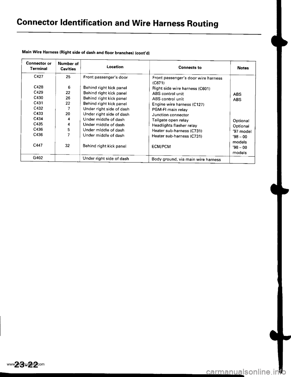
Connector ldentification and Wire Harness Routing
Main Wire Harness {Right side of dash and floor branchesl {cont,dl
Connector or
Tsrminal
Number ol
CavitiesLocationConnects toNotes
c427
c428
c429
c430
c431
c432
c433
c434
c435
c436
c436
c447
6
26
22
7
20
5
7
25Front passenger's door
Behind right kick panel
Behind right kick panel
Behind right kick panel
Behind right kick panel
Under right side of dash
Under .ight side of dash
Under middle of dash
Under middle of dash
Under middle of dash
Under middle of dash
Behind right kick panel
Front passenger's door wire harness(c671)
Right side wire harness {C601)ABS control unit
ABS control unit
Engine wire harness (C127)
PGM-Fl main relay
JUnotron connector
Tailgate open relay
Headlights f lasher relay
Heater sub-harness (C731 )Heater sub-harness (C731)
ECM/PCM
ABS
ABS
Optional
Optional'97 model'98 - 00
models'98 - 00
mooets
G402Under right side of dashBody ground, via main wire harness
23-22
www.emanualpro.com
Page 1184 of 1395
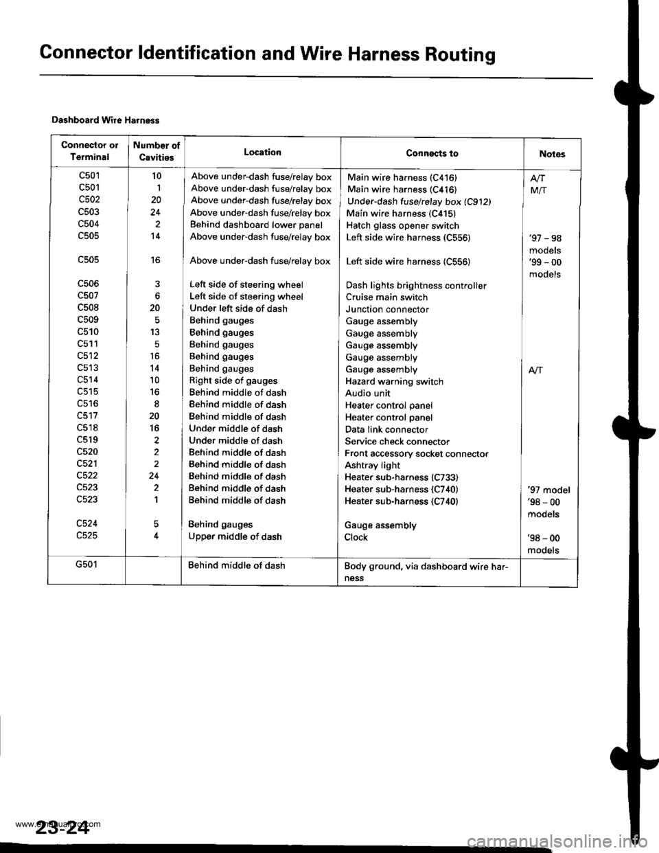
Connector ldentification and Wire Harness Routing
Dashboard Wire Harness
Connector ol
Terminal
Numb€r of
CavitiesLocationConngcts toNotes
c501
c501
c502
c503
c504
c505
c506
c507
c508
c509
c510
c511
c512
c514
c518
c519
c520
c521
c524
10
1
20
14
16
6
20
13
5
t6
14
10
to
20
16
2
24
2
1
5
Above under-dash fuse/relay box
Above under-dash fuse/relay box
Above under-dash fusehelay box
Above under-dash fuse/relay box
Behind dashboard lower panel
Above under-dash fuse/relay box
Above under-dash fuse/relay box
Left side of steering wheel
Left side of steering wheel
Under left side of dash
Behind gauges
Behind gauges
Behind gauges
Behind gauges
Behind gauges
Right side of gauges
Behind middle of dash
Behind middle of dash
Behind middle of dash
Under middle of dash
Under middle of dash
Behind middle of dash
Behind middle of dash
Behind middle of dash
Behind middle of dash
Behind middle of dash
Behind gauges
Upper middle of dash
Main wire harness (C416)
Main wire harness (C416)
Under-dash fuse/relay box 1C912)
Main wire harness (C415)
Hatch glass opener switch
Left side wire harness (C556)
Left side wire harness (C556)
Dash lights brightness cont.oller
Cruise main switch
Junction connector
Gauge assembly
Gauge assembly
Gauge assembly
Gauge assembly
Gauge assembly
Hazard warning switch
Audio unit
Heater control panel
Heater control panel
Data link connector
Service check connector
Front accessory socket connector
Ashtray light
Heater sub-harness (C733)
Heater sub-harness {C740}
Heater sub-harness (C740)
Gauge assembly
Clock
'97 - 98
models'99 - 00
models
Mir
A/r
'97 model'98 - 00
mooets
'98 - 00
models
G501Behind middle of dashBody ground, via dashboard wire har-
ness
23-24
www.emanualpro.com