4-5 HONDA CR-V 2000 RD1-RD3 / 1.G Owner's Manual
[x] Cancel search | Manufacturer: HONDA, Model Year: 2000, Model line: CR-V, Model: HONDA CR-V 2000 RD1-RD3 / 1.GPages: 1395, PDF Size: 35.62 MB
Page 1350 of 1395
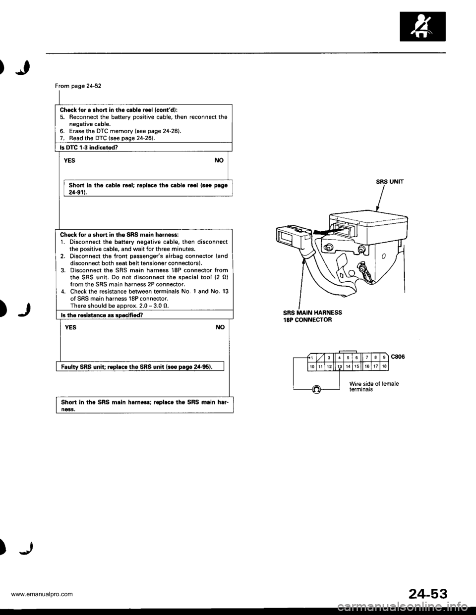
From page 24-52
Chock for a shon in th6 cablo recl {cont'dl:5. Reconnect the battery oositive cable, then reconnect thanegative cable.6. Ersse the DTC memory (see page 24-28).7. Read the DTC (see page 24-26l'.
ls DTC 'l-3 indic{tod?
NOYES
Short in the csble reel; replace tha cabls rcol lsao paga
24-911.
Chock for a short in th€ SRS main ha.nors:1. Disconnect the battery negative cable, th€n disconnectthe Dositive cable, and wait for three minutes.2. Disconn€ct tho lront passengor's airbag connector (and
disconnect both seat belt tensioner connectors).3. Disconnect the SRS main harness 18P connector fromthe SRS {rnit. Do not disconnect the special tool (2 0)from the SRS main harness 2P connector.4. Check the resistance between terminals No. 1 and No. 13of SRS main harness 18P connector.There should be aDorox. 2.0 - 3.0 0.
b th€ rsciitlnce a3 sDecifi6d?
NOYES
Faulty SRS unit; rspl.c. th6 SRS unit l.co p.sc 2a-95,,
Shori in the SRS m.in h.rn.e!; ropbce the SRS main htr-ne33.
SRS UNIT
)SRS MAIN HABNESS18P CONNECTOR
c806
)
(., Lzl 3 ll63
1518
Wire side ottormrnats
24-53
www.emanualpro.com
Page 1351 of 1395
Troubleshooting
DTC 1-4
CAUTION: Whonover the ignition switch is ON (ll), or
has boen turned OFF for less than throe minutos, bs
carelul nol to bump tho SRS unit; the airbags could
accidentally deploy and cause damago or iniuri63.
ial
ltl
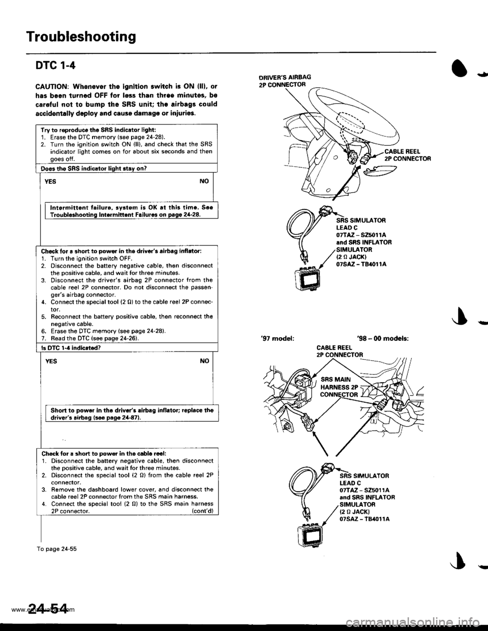
REEL2P CONNECTOR
SIMULATORLEAD C
ffi
07TAZ - SZ5011A.rd SRS INFIATOR
/SIMULATOR./ ea JA0KI
1( otstz-terore
'98 - 00 models:
CABLE REEL
'97 model:
SIMULATORI-EAD C07TAZ - SZ5011Aand SRS INFLATORSIMULATOR(2 0 JACKT07sAz - lB4011A
Try to rop.oduco tho SRS indicator light:1. Erase the DTC momory (soe page 24-28).2. Turn the ignition switch ON {ll}, and check that the SRSindicator light comes on for about six seconds and thengoes off.
Doe3 th6 SRS indicltor light 3tay on?
YESNO
Intormittent tailure, rystem is OK rt this timo. SeeTroubl$hooting Intermittent Failurcs on pago 2G28.
Chack lor a 3hort to powor in ths driyar's airbag inflrtor:1. Turn the ignition swilch OFF.2. Disconnect the battery negative cable, th€n disconnectthe positive cable, and wait for three minutes.3. Disconnect the driver's airbag 2P connector {rom thecable reel 2P connector. Do not disconnect the passen-ger's airbag connector.4. Connect the special tool (2 0) to the cable reel 2P conn6c-tor,5. Reconn€ct the battery positive cable. then reconnect thenegative cable.6. Erase the DTC memory (see page 24-28).7. Read the DTC {see page 24-261.
ls DTC 1-4 indicatod?
NOYES
Short to powe. in the driv.r's rirbrg inflator; replace theddver's airbeq (!o€ D.qa 2447).
Ch€ck for. short to powe. in tho cabl6.ool:1. Disconnect the battery negative cable, then disconnectthe oositive cable, and wait lor three minutes.2. Disconnect the special tool (2 O) from the cable reel 2Pconnefior,3- Remove the dashboard lower cover, and disconnect thecable reel 2P connector lrom the SRS main harness.4. Connect the special tool (2 0) to the SRS ma;n harn€ss2P connoctor. (cont'dl
To page 24-55
24-54
!
www.emanualpro.com
Page 1352 of 1395
Ftom page24-54
Check for 6 short power in the cable r6el {cont'd):5. Reconnect the battery positive cable, then reconnect thenegative cable.6. Erase the DTC memory (see page 24-28).7. Read the DTC (see page 24-261.
b DTC 1-4 indicarodz
YESNO
Short to power in lhe cablo roel; replace th€ cabl€ ieel{see pago 24-91).
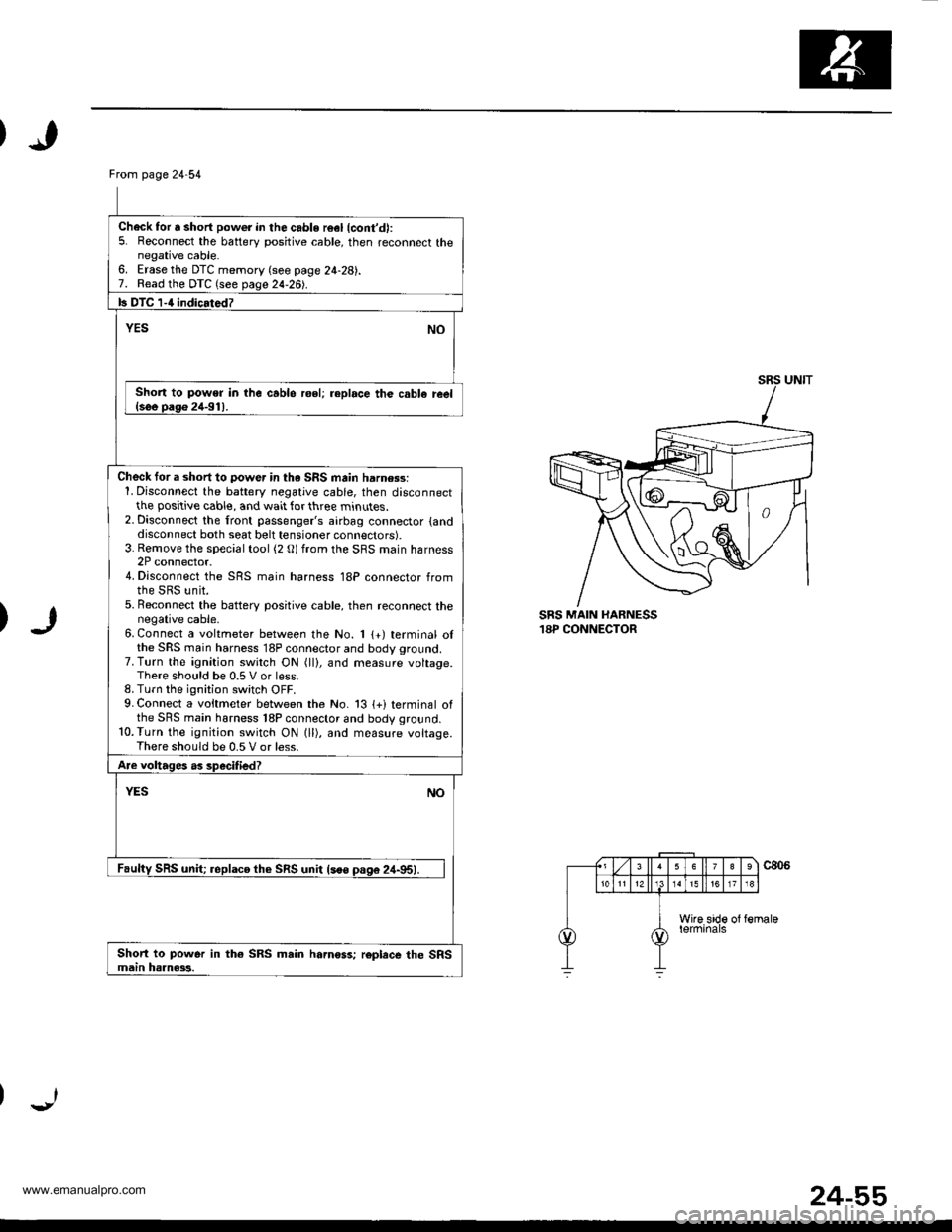
Check tor a short to power in th. SRS main harn$s:1. Disconnect the battery negative cable, then disconnectthe positive cable, and wait for three minutes.2. Disconnect the front passenger's airbag connector {anddisconnect both seat belt tensioner connectors).3. Rernove the special tool (2 O) from the SRS main harness2P connector.4. Disconnect the SRS main harness 18P connector fromthe SRS unit.5. Beconnect the batterv positive cable, then reconnect thenegative cable.6. Connect a voltmeter between the No. 1 {+) terminal olthe SRS main harness 18P connector and body ground.7. Turn the ignition switch ON (ll), and measure voltage.There should be 0.5 V or less.8. Turn the ignition switch OFF.9. Connect a voitmeter between the No. 13 {+i terminal ofthe SRS main harness 18P connector and body ground.10.Turn the ignition switch ON lll), and measure voltage.There should be 0.5 V or less.
Are voltages as specified?
YESNO
Faulty SRS unit; replaco th€ SRS unit lsoo pas6 24-95).
Short to power in th€ SRS main hamoss; roplece the SRSmain haanass.
SRS MAIN HARNESS18P CONNECTOR
24-55
www.emanualpro.com
Page 1353 of 1395
Troubleshooting
DTC l-s
CAUTION: Whenever tho igniiion switch is ON {ll), or
has been lurned OFF for loss lhan thrse minules, be
caretul not to bump the SRS unit; the airbags could
accidentally deploy and cause damage or iniuries.
O'-
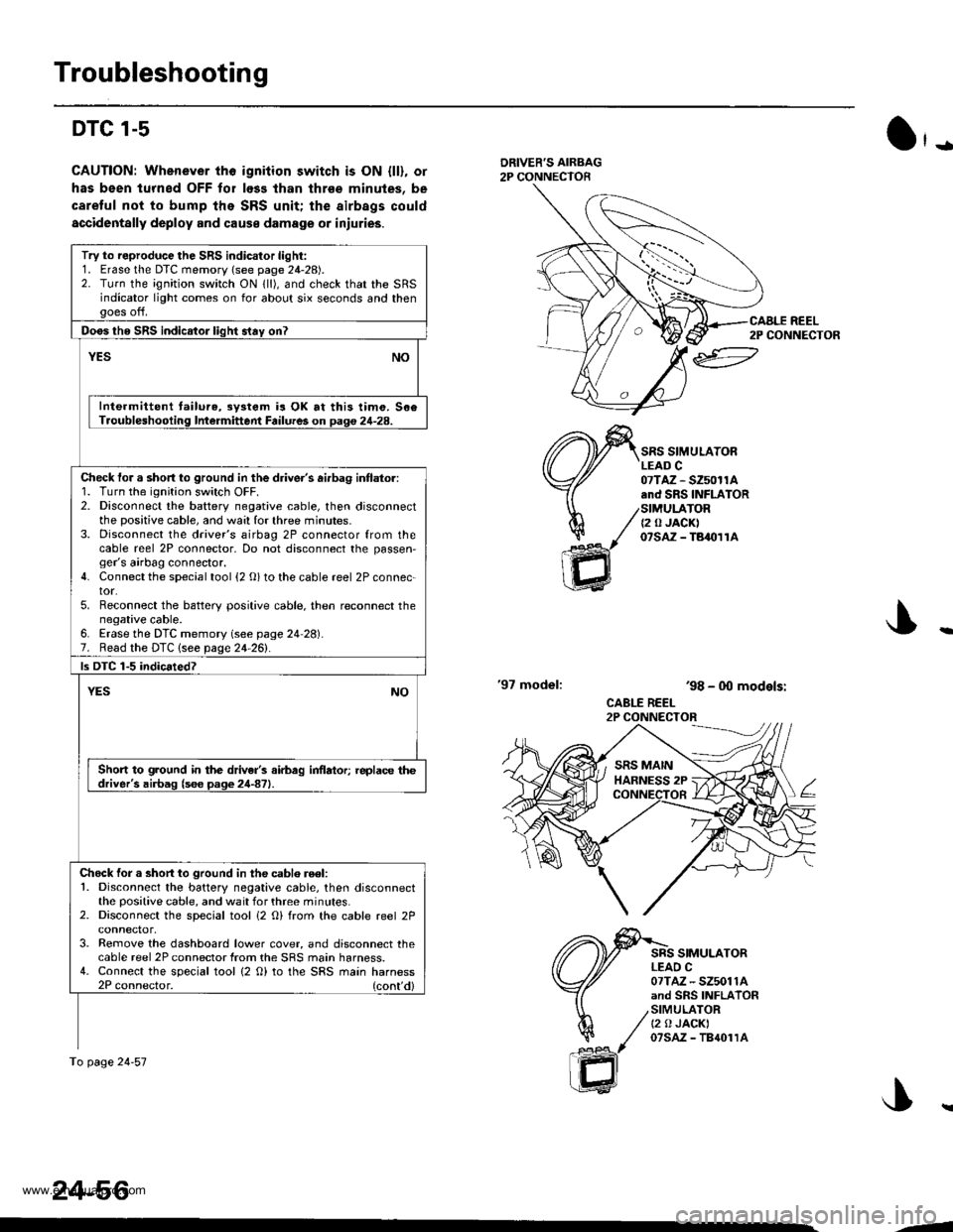
DRIVER'S AIRBAG2P CONNECTOR
'97 model:
SRS SIMULATORLEAD C07TAZ - SZ50r1A.nd SRS INFLATORSIMULATOR{2 0 JACK)07sAz - TBaolrA
SRS SIMULATORLEAO C07TAZ - SZ5011Aand SRS INFLATORSIMULATORt2 0 JACKI07sAz - TB{01rA
ar
h/
ffi
'98 - 0O models:
CABLE REEL2P CONNECTOR
Try to reproduce the SRS indicator light:1. Erase the DTC memory (see page 24-28).2. Turn the ignition switch ON lll), and check that the SRSindicator light comes on for about six seconds and thengoes off.
Doos tho SRS indicator liqht stav on?
YESNO
Inte.mittent tailure,3y3tem is OK at this timo. 506Troubleshooling Intermittent Failures on Daq€ 24-28.
Check tor a short to ground in the driver's ai.bag intlator:1. Turn the ignition switch OFF.2. Disconnect the battery negative cable, then disconnectthe positive cable, and wa:l for three minutes.3. Disconnect the driver's airbag 2P connector from thecable reel 2P connector, Do not disconnect the passen,ger's airbag connector.4. Connect the special tool {2 O} to the cable reel 2P connec-tor.5. Reconnect the battery positive cable. then reconnect thenegative cable.6. Erase the DTC memory (see page 24 28).7. Read the DTC lsee page 24-261.
ls DTC 1-5 indicated?
YESNO
Short to ground in the driver's airbag inflator; replace thedriver's airbag (s6e page 24-871.
Chock for a short to ground in the cablo reel:1. Disconnect the battery negative cable, then disconnectthe positive cable, and wait for three minutes.2. Disconnect the special tool i2 O) from the cable reel 2P
3. Remove the dashboard lower cover, and disconnect thecable reel 2P connector from the SRS main harness.4. Connect the special tool {2 O) to the SRS main harness2P connector. (cont'd)
To page 24-57
24-56
CAALE REEL2P CONNECTOR
J..
.J
www.emanualpro.com
Page 1354 of 1395
)
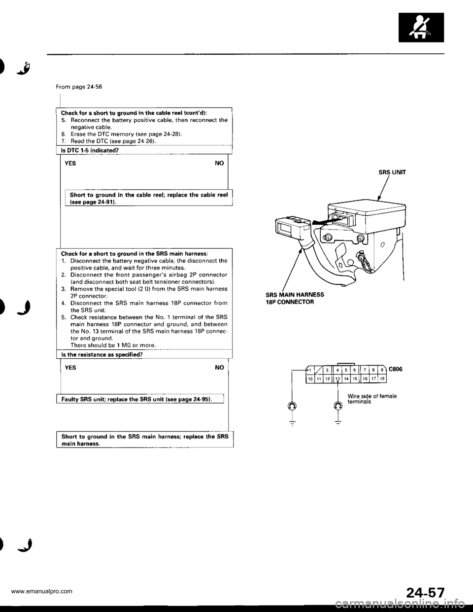
SRS MAIN HARNESS18P CONNECTOR
)
From page 24 56
Check{or a short to ground in the cable reel (cont'd):
5. Reconnect the batterv positive cable, then reconnect thenegative cable.6. Erase lhe DTC memoty lsee page 24-28).7. Read the DTC lsee page 24 26).
ls OTC 1-5 indicated?
YESNO
Short lo ground in the cable reel; replace the cable reel{see oaoe 2,1-91}.
Check for a short to ground in the SRS main harness:'1. Disconnect the battery negative cable, the disconnect thepositive cable, and wait for three minutes.2. Disconnect the tront passenger's airbag 2P connector(6nd disconnect both seat belt tensioner connectors).3. Remove the special tool 12 {))from the SRS main harness2P connector.4- Disconnect the SRS main harness 18P connector fromthe sRs unit.5. Check resistance between the No. l terminal o{theSRSmain harness 18P connector and ground, and betweenthe No. 13 terminal of the SRS main harness 18P connec-tor and ground.There should be I M0 or more.
ls lhe resistance as soecitiod?
NOYES
Faulw SRS unit reDlace the SRS unit lsee paqe 24-951.
Short to ground in the SRS main harness; replace the SRSmain ham€ss,
24-57
www.emanualpro.com
Page 1355 of 1395
Troubleshooting
DTC 2-1 and DTC 2-2
CAUTION: Whenever the ignition switch is ON lll), or
has been turned OFF tor less than throe minutes, be
careful not to bump the SRS unit; the airbags could
accidentally deploy and cause damage or iniuries.
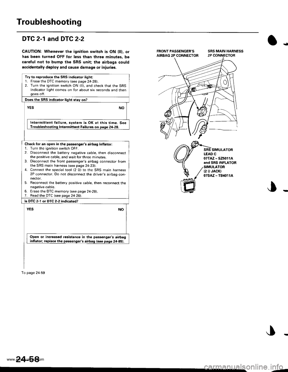
SRS MAIN HARNESS
SIMULATORI-EAD C
!a
07TAZ - SZ5tt11Aand SRS INFLATOR
/StMULATOR/ Q A JACKI
y' 07slz-TA411A
ffi
Try to reproduce the SRS indicator light:1. Erase the DTC memory (see page 24-28).2. Turn the ignition switch ON (ll), and check that the SRSindacator light comes on for about sax seconds and then
Does the SRS indicator lioht stav on?
Intermittent tailure, svstem is OK ai lhis time. SeeTroubl*hooting Intermittent Failures on paqe 24-28.
Chock for an open in the passongor's airbag inflator:1. Turn the ignition switch OFF.2. Disconnect the battery negative cable, then disconnectthe positive cable, and wait for three minutes.3- Disconnect the front passenger's airbag connector lromthe SRS main harness (see page 24-2:,,.4. Connect the special tool (2 0) to the SRS main harness2P connector. Do not disconnect the driver's airbag con,nector.5. Reconnect the battery positive cable, then reconnect thenegative cable.6. Erase the DTC memory (see page 24-28).7. Read the DTC (see page 24 26!'.
ls DTC 2-1 or DTC 2-2 indicated?
Open or incrcased resistance in tho passenger's airbag
To page 24'59
24-58
--
www.emanualpro.com
Page 1356 of 1395
)
From page 24 58
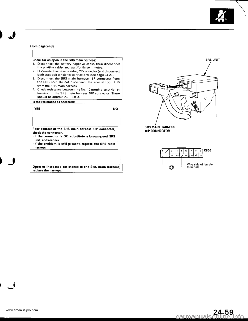
Check fo. an oD6n in the SRS main harness:1. Disconnect the battery negative cable, then disconnectthe positive cable, and wait for three minutes.2. Disconnectthe driver's airbag 2P connector land disconnectboth seat belt tensioner connectors) (see page 24 23).3. Disconnect the SRS main harness 18P connector fromthe SRS unit. Do not disconnect the soecial tool (2 Oifrom the SRS main harness.4. Check resistance between the No. 10 terminal and No. 14terminal of the SRS main harness 18P connector. Thereshould be aoorox. 2.0 - 3.0 g.
ls the .osistanc€ as soecified?
NOYES
Poor contacl ai the SRS main harness 18P connecloricheck lhe connector,.lf the conneclor is OK, substitute a known-good SRSunit, and recheck..lf the problem is still present, replace the SRS mainhatnesli,
Open or increased resistance in the SRS main harness;replace the harness.
UNITsRs
18P CONNECTOR
24-59
www.emanualpro.com
Page 1377 of 1395
Troubleshooting
DTC 4-5
GAUTION: Whonever the ignition switch is ON fll). olhas be6n turned OFF for less than thrso minuter. becareful not to bump the SRS unit; the airbags couldaccidontally deploy and causo damage or iniurias.
\
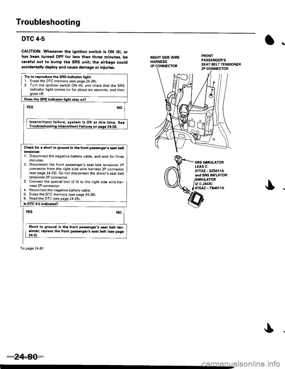
RIGXT SIOE WIREHARNESS2P
FRONTPASSENG€R'S
SRS SIMULATORLEAD C07lAz - s2501 1Aand SRS INFLATORSIMULATOR
t2 0 JACKTo?saz - Taaol 1A
Try to roproduco th. SRS indicrtor tighi:1. Erase the DTC memory (see page 24-28).2. Turn the ignition switch ON (ll), and check that the SRSindicator light comes on for about six seconds, and thengoes off.
Doe3 the SRS indicator light stay on?
YESNO
Int€rmittent t.ilurG, syst.m is OK at thi! timo. So€Troubleshooting Inte.mift€nt Failure3 on psqa 2+28.
Chcck Ior a shon to ground in the trodt pars€nge/s lert behtensionea:1. Disconnect the negative battery cable, and wait for threemrnutes.2. Disconnect the front passenger's seat belt tensioner 2pconnector trom the right side wire harness 2p connector(see page 24-23). Do not disconnect the driver's seat bektensioner 2P connector.3. Connect the special tool (2 0) to the right side wire har-ness 2P connector,4. Reconnect the negative battery cable.5. Erase the DTC memory lsee page 24-28).6. Read the DTC (seo page 24-26!-.
k DIC G5 indicated?
NOYES
Short to ground in the Lont passengc.'3 3€rt boh ton-sioner; replace tho from p.rlenger's sort beh ls€a page21-3t.
To page 24-81
24-80
www.emanualpro.com
Page 1378 of 1395
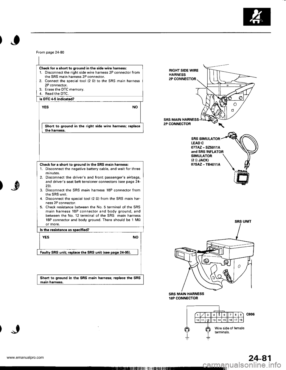
From page 24'80
Check lor a short to ground in the sido wir€ harness:1. Disconnect the rightsidewire harness 2P connector fromthe SRS main harness 2P connector.2. Connect the special tool {2 O) to the SRS main harness2P connector.3. Erase the DTC memorv.4. Read the DTC.
b DTC 4-5 indicrtad?
YESNO
Short to ground in the right side wire harness; replac.the harne3!.
Check tor a short io ground in the SRS main ha.nessi1. Disconnect the negative battery cable, and wait for threeminotes,2. Disconnect the driver's and front passenger's airbags,and driver's seat belt tonsioner connectors (see page 24-231.3. Disconnect the SRS main harness 18P connector from
4. Disconnect the special tool (2 0) from the SRS main har-ness 2P connector.5. Check resistance between the No. 5 terminal oI the SRSmain harness 18P connector and body ground, andbetween the No. 12 terminal of the SRS main harness18P connector and body ground. There should be 1 M0or more,
b th€ re3i3tance as specified?
NOYES
Faulty SRS unit replace the SRS unit {see pace 2a-951.
Short to ground in the SRS main harness; replace the SRSmain harnoss.
RIGHT SIDE WIREHARNESS2P CONNECTOR
SRS MAIN HARNESS2P CONNECTOR
SRS SIMULATORLEAD C07TAz - SZ5011Aand SRS INFLATORSIMULATOR \{2 0 JACK} \07SAZ-TB,O114 \I
ffi
)
SRS MAIN HANNESS18P CONNECTOR
24-81
www.emanualpro.com