4-5 HONDA CR-V 2000 RD1-RD3 / 1.G Workshop Manual
[x] Cancel search | Manufacturer: HONDA, Model Year: 2000, Model line: CR-V, Model: HONDA CR-V 2000 RD1-RD3 / 1.GPages: 1395, PDF Size: 35.62 MB
Page 51 of 1395
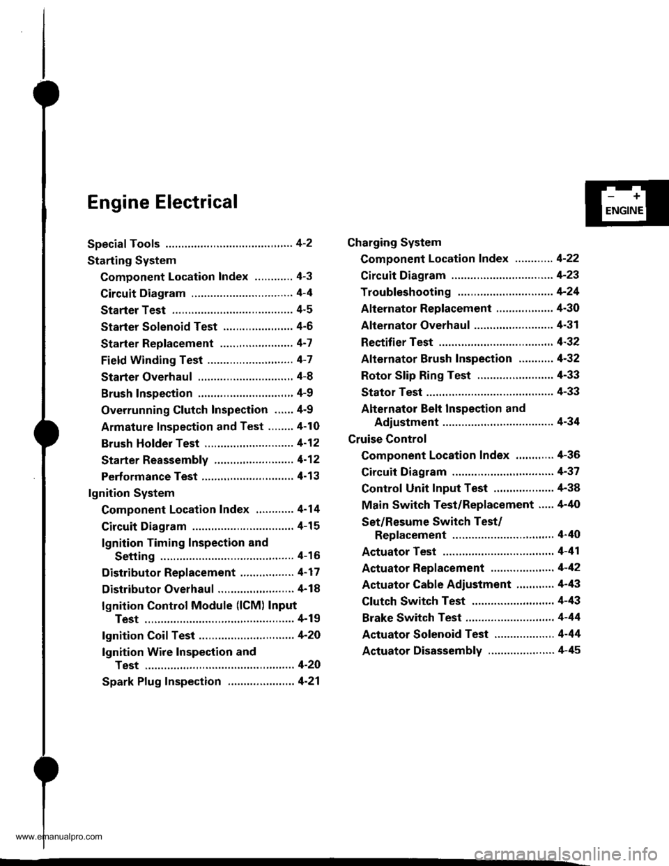
Engine Electrical
Speciaf Tools ............. 4-2
Starting System
Component Location Index ............ 4-3
Circuit Diagram ................................ 4-4
Starter Test ........... 4-5
Starter Solenoid Test ...................... 4'5
Starter Replacement ....................... 4-7
Field Winding Test ........................... 4-7
Starter Overhaul ............................,. 4-8
Brush Inspection ...........................,., 4-9
Overrunning Glutch Inspection ...... 4-9
Armature lnspection and Test ........4-10
Brush Holder Test ............................ 4-12
Starter Reassemb|y ......................... 4-1 2
Perf ormance Test ............................. 4- 1 3
lgnition System
Component Location Index ............ 4-14
Circuit Diagram ................................ 4-15
lgnition Timing Inspection and
Setting .......................................... 4-16
Distributor Replacement ........,........ 4-17
Distributor Overhaul .............,,......... 4-18
lgnition Control Module (lCM) Input
Test ..............................,................ 4-19
fgnition Coil Test .............................. 4-2O
lgnition Wire Inspection and
Test ............................................... 4-20
Spark Plug Inspection ..................... 4-21
-+
ENGINE
Charging System
Component Location Index ............ 4-22
Circuit Diagram ....................,........... 4-23
Troubleshooting .............................. 4-24
Alternator Replacement ..........,....... 4-30
Alternator Overhaul .......,,................ 4-31
Rectifier Test .........4-32
Alternator Brush Inspection ........... 4-32
Rotor Slip Ring Test ........................ 4-33
Stator Test ............. 4-33
Alternator Belt Inspection and
Adiustment ........4-34
Gruise Control
Component Location Index .,,,........ 4-36
Circuit Diagram ................................ 4-37
Control Unit Input Test ................... 4-38
Main Switch Test/Replacement ..... 4-40
Set/Resume Switch Test/
Replacement .......................,........ 4'40
Actuator Test ....,,., 4-41
Actuator Replacement ...............,.... 4-42
Actuator Cable Adiustment ............ 4-43
Clutch Switch Test .......................... 4-43
Brake Switch Test .................. .......... 4-44
Actuator Solenoid Test .............. ...,. 4-44
Actuator Disassembly ..................... 4-45
www.emanualpro.com
Page 55 of 1395

Starting System
Starter Test
NOTE: The air temperature must be between 59 and'100'F (15 and 38"C) before testing.
Recommended Procedure:
. Use a staner system tester.
. Connect and operate the equipment in accordance
with the manufacturer's instructions.
. Test and troubleshoot as described.
Alte.nate Procedure:
. Use the following equipment:- Ammeter, 0 - 400 A- Voltmeter, 0 - 20 V (accurate within 0.1 volt)
Tachometer,0 - 1,200 rpm
. Hook up a voltmeter and ammeter as shown.
NOTE: After this test, or any subsequent repair. reset
the ECM/PCM to clear any codes (see section 1 1).
Check the Starter Engagement:
'1. Remove the No. 44 (15 A) fuse from the under-hood
fuse/relay box.
2. Turn the ignition switch to START (lll) with the shift
lever in E or E position (A/T) or with the clutch
pedal depressed {M/T). The starter should crank the
eng ine.
. lf the starter does not crank the engine, go to
step 3.
. lf it cranks the engine erratically or too slowly, go
to "Check for Wear and Damage" on the next
page.
NEGATIVE TERMINAL
4.
5.
6.
7.
8.
Check the battery, battery positive cable, ground.
staner cut relay, and the wire connections for loose-
ness and corrosion. Test again.
lf the staner still does not crank the engine, go to
step 4.
Unplug the connector (BLK /VHT wire and solenoid
terminal) from the starter.
Connect a jumper wire from the baftery positive (+)
terminal to the solenoid terminal.
The starter should crank the engine.
. lf the starter still does not crank the engine,
remove it, and diagnose its internal problem.
. lf the starter cranks the engine, go to step 6.
Check the ignition switch (see section 23).
Check the starter cut relay {see section 23}.
Check the IVT gear position switch (A/T) or the clutch
interlock switch (M[).
Check for an open in the wire between the ignition
switch and starter.
(cont'd)
4-5
www.emanualpro.com
Page 518 of 1395
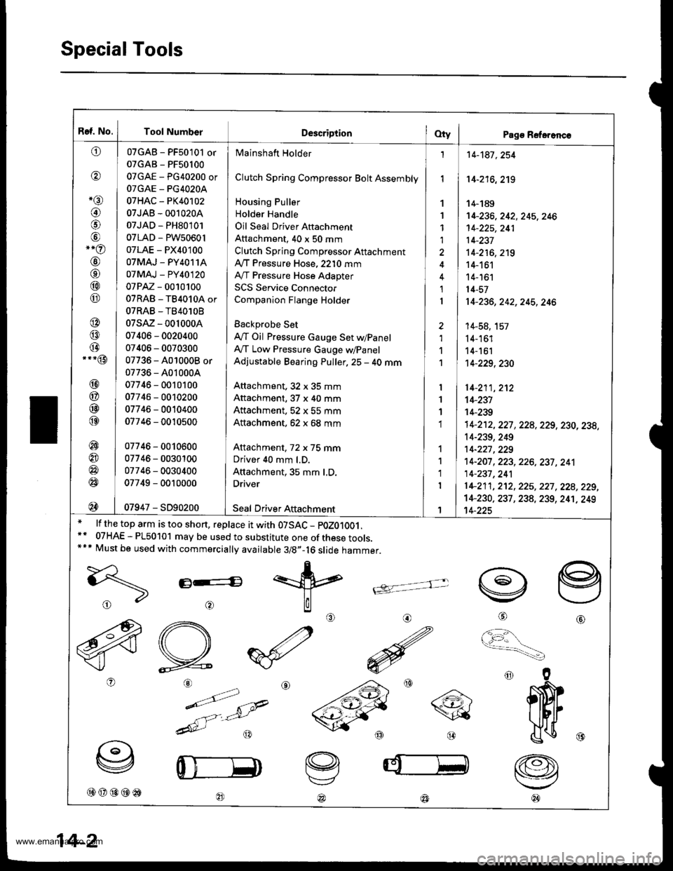
Ref. No.
^tl)
@
*rar
@
@
,-o
@
o
@
@
@
@
@.--@
@
@
@
@
@
@
@
@
@
Tool NumberDescriptionOty I Pago Referonc€
Mainshaft Holder
Clutch Spring Compressor Bolt Assembly
Housing Puller
Holder Handle
Oil Seal Driver Aftachment
Attachment, 40 x 50 mm
Clutch Spring Compressor Attachment
Ay'T Pressure Hose, 2210 mm
IVT Pressure Hose Adapter
SCS Service Connector
Companion Flange Holder
Backprobe Set
lVT Oil Pressure Gauge Set w/Panel
A,/T Low Pressure Gauge w/Panel
Adjustable Bearing Puller, 25 - 40 mm
Anachment, 32 x 35 mm
Attachment, 37 x 40 mm
Attachment. 52 x 55 mm
Attachment. 62 x 68 mm
Attachment, 72 x 75 mm
Driver 40 mm l.D.
Attachment, 35 mm LD.
Driver
07GAB - PF50101 or
07GAB - PF50100
07GAE - PG40200 or
OTGAE _ PG4O2OA
07HAC - PK40102
07JAB - 001020A
07JAD - PH80101
07LAD - PW50601
07LAE - PX40100
OTMAJ - PY4O114
07MAJ - PY40120
07 PAZ - 0010100
07RAB - TB4010A or
07RAB.TB40lOB
07sAz - 001000A
07406 - 0020400
07406 - 0070300
07736 - 4010008 or
07736 - A010004
07746 - 0010100
07746 - 0010200
07746 - 0010400
07746 - 0010500
07746 - 0010600
07746 - 0030100
07746 - 0030400
07749 - 0010000
07947 - SD90200Seal Driver Aftachment
1
1
1
1,l
1
I
2
1'l
1
I
1
1
1
1
1
1
I
1
14-181 , 254
14-216,219
14-189't4-236,242,245,246
't 4-225, 241
14-237
14-216,2't9
14-161
14- 161
14-57
14-236,242,245,246
14-58, 157
14-161
14-161'14-229,230
14-211, 2't2
14-231
14-239
14-212, 227 , 228,229, 230, 238,
14-239, 249
14-221 ,229't 4-207 , 223,226, 237 , 241
14-237,241
1 +21 1, 2't2, 225, 227, 228, 229,
14-230, 237 , 238, 239, 24't, 249't4-225
lf the top arm is too short, replace it with 07SAC - pOZ01OO1.
07HAE - PL50101 may be used to substitute one of these tools.Must be used with commercially available 3/8"-16 slide hammer.
E----G
@@@@@
@
tvj
'
@@@)
14-2
www.emanualpro.com
Page 521 of 1395
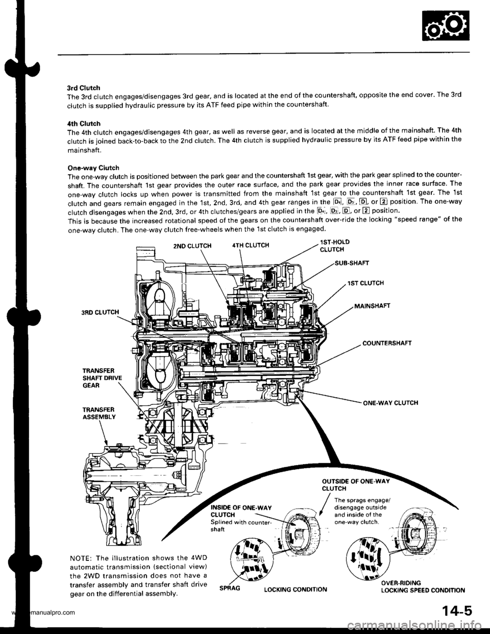
3rd Clutch
The 3rd clutch engages/disengages 3rd gear, and is located at the end of the countershaft, opposite the end cover. The 3rd
clutch is supplied hydraulic pressure by its ATF feed pipe within the countershaft.
ilth Clutch
The 4th clutch engages/disengages 4th gear, as well as reverse gear, and is located at the middle of the mainshaft. The 4th
clutch is joined back-to-back to the 2nd clutch. The 4th clutch is supplied hydraulic pressure by its ATF feed pipe within the
mainshaft.
One-way Clutch
The one-way clutch is positioned between the park gear and the countershaft 1st gear, with the park gear splined to the counter-
shaft. The countershaft 1st gear provides the outer race surface, and the park gear provides the inner race surface The
one,way clutch locks up when power is transmitted from the mainshaft lst gear to the countershaft 1st gear. The 1st
clutch and gears remain engaged in the 1st, 2nd, 3rd, and 4th gear ranges in the lo], pt, E, or E position The one-way
clutch disengages when the 2nd, 3rd, or 4th clutches/gears are applied in the lor, [d, E, or E position'
This is because the increased rotational speed of the gears on the countershaft over-ride the locking "speed range" of the
one-wav clutch. The one-wav clutch free-wheels when the lst clutch is engaged
lST.HOLDCLUTCH
1ST CLUTCH
MAINSHAFT3RD CLUTCH
COUNTERSHAFT
TRANSFERSHAFT DRIVEGEAR
TRANSFERASSEMBLY
NOTE: The illustration shows the 4WD
automatic transmission {sectional view)
the 2WD transmission does not have a
transfer assembly and transfer shaft drive
gear on the differential assembly.
2NO CLUTCH4TH CLUTCH
INSIDE OF ONE.WAYCLUTCH
ONE.WAY CLUTCH
OUTSIDE OF ONE.WAYCLUTCH
The sprags engage/disengage outsideand inside of theSplined with counter- -
shaft
OVER.RIOINGLOCKING SPEED CONOITIONLOCKING CONDITION
14-5,
www.emanualpro.com
Page 566 of 1395
![HONDA CR-V 2000 RD1-RD3 / 1.G Workshop Manual
PCM Circuit Diagram (A/T Gontrol System)
98 Model
UNOEF-HOOO FUSAFELAY sox
_YEL_
09 lD0 lDl,l lDl5
PNK BLU
F rronr
f-r------}-er
F_ cRN _______]_f- PN(
F_ GFNTBLX
F_ gnN
*,,,,)83HfL
f *-> 311 HONDA CR-V 2000 RD1-RD3 / 1.G Workshop Manual
PCM Circuit Diagram (A/T Gontrol System)
98 Model
UNOEF-HOOO FUSAFELAY sox
_YEL_
09 lD0 lDl,l lDl5
PNK BLU
F rronr
f-r------}-er
F_ cRN _______]_f- PN(
F_ GFNTBLX
F_ gnN
*,,,,)83HfL
f *-> 311](/img/13/5778/w960_5778-565.png)
PCM Circuit Diagram (A/T Gontrol System)
'98 Model
UNOEF-HOOO FUSAFELAY sox
_YEL_
09 lD0 lDl,l lDl5
PNK BLU
F rronr
f-'r'------}-'er'
F_ cRN _______]_f- PN(
F_ GFNTBLX
F_ gnN
*,',,,)83Hf'L
f *'-> 3111"?"
I
1*[-lll-,I I Gro]
UNOEF-DASHFUSE/BELAYBOX
I
rGD2 I ocr I oG2 | V8 S0. I SIOP SW I CAs
ATP IDl ,ATP , ATP , A-P , ATP , A_PNP lrND lR lD4 lD3 12 ll
sr{rTat
14-50
www.emanualpro.com
Page 568 of 1395
![HONDA CR-V 2000 RD1-RD3 / 1.G Workshop Manual
PCM Circuit Diagram (A/T Control System)
99 - 00 Models
IJNOERHOOD FUSE/FELAY EoXEATTERY
IJNOER DASIIFUS/FELAYBOX
-]-
T8LKryEL
l.
]T
IBLX,YEL
D9 100 | 0r4 | Drt I Btg
GAUGEASSEMELYFffi[t**
f Lom HONDA CR-V 2000 RD1-RD3 / 1.G Workshop Manual
PCM Circuit Diagram (A/T Control System)
99 - 00 Models
IJNOERHOOD FUSE/FELAY EoXEATTERY
IJNOER DASIIFUS/FELAYBOX
-]-
T8LKryEL
l.
]T
IBLX,YEL
D9 100 | 0r4 | Drt I Btg
GAUGEASSEMELYFffi[t**
f Lom](/img/13/5778/w960_5778-567.png)
PCM Circuit Diagram (A/T Control System)
'99 - 00 Models
IJNOER'HOOD FUSE/FELAY EoXEATTERY
IJNOER DASIIFUS'/FELAYBOX
-]-
T8LKryEL
l.
]T
IBLX,'YEL
D9 100 | 0r4 | Drt I Btg
GAUGEASSEMELYFffi[t**
f L'om {+ sr&BrLr --1 l-
LTGRN
BLKtsLU
FED
YEL
8LU
LI BLU
F-lwr-i
|--FED----.1
|-BFN--
f- Lr sLrJ -l
,I,-r
G4o1
d
G401
AIP,O,0,ATP,ArPlO/D04 t5w t2 tr tN0
){:-\
!r'TGEAF POS]IION
14-52
www.emanualpro.com
Page 570 of 1395

PCM Terminal Voltage/Measuring Conditions
A/T Control System -'98 - 00 Models
The PCM terminal voltage and measuring conditions are shown for the connector terminals that are related to the A"/T con-
trol system. The other PCM terminal voltage and measuring conditions are described in section 11.
FCM Connector Terminal Localions
NOTE: 819 and C3 terminalsare applied to'99 - 00 models.
o (16Pt
T6rminal NumberSignalDescriptionMeasuring Conditions/Terminal Voltage
A5CRSDownshift signal input from
cruise control unit
When cruise control is used; Pulsing signal
A10scsTiming and adjustment service
check signal (5 V from PCM)
With ignition switch ON (ll) and service check
connector open:5 V
With ignition switch ON (ll) and service check
connector jumped with special tool: 0 V
A14('98 model)
D4 INDD4 indicator light control
{Voltage from PCM turns D4 light
oN)
When ignition switch is first turned ON (ll):
Battery voltage for two seconds
In E position: Battery voltage
A14
('99 - 00 models)
D INDD indicator light control(Voltage from PCM turns D light
oN)
When ignition switch is first turned ON (ll):
Baftery voltage for two seconds
ln E position: Battery voltage
428ILUInterlock control(Voltage from PCM)
When ignition switch ON {ll), brake pedal
depressed, and accelerator pedal released:
Battery voltage
A.32STOP SWBrake switch signal inputBrake pedal pressed; Battery voltage
Brake pedal released: 0 V
FCM CONNECTOR B I25P}
Terminal NumberSignalDescriptionMeasuring Conditions/Terminal Voltage
B1IGPlPower supply circuit from main
relay via under-hood Fuse 44
With ignition switch ON {ll): Battery voltage
With ignition switch OFF: 0 V
82PG1Ground (G101)
B8LSMLinear solenoid power supply
negative electrode
IG P2Power supply circuit from main
relay
With ignition switch ON (ll): Baftery voltage
With ignition switch OFF: 0 V
810PG2Ground (G101)
B17Linear solenoid power supply
positive electrode
With ignition switch ON (ll): Pulsing signal
819
('99 - 00 models)
O/D INDOver-Drive (O/D) OFF indicator
light control
When ignition switch is first turned ON (ll):
0 V for two seconds
O/D OFF indicator light ON:0 V
O/D OFF indicator light OFF: Battery voltage
s20Ground (G101)
B�21VBUBack-up power supply(under-hood Fuse 47)
Always battery voltage
B�22LG2Ground (G101)
14-54
www.emanualpro.com
Page 571 of 1395
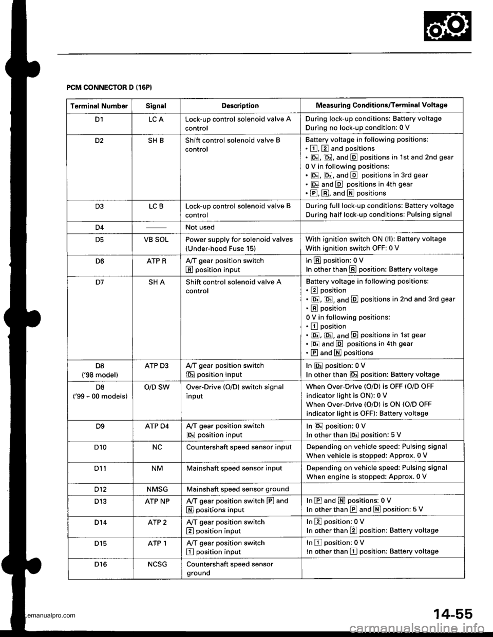
Terminal NumborSignalDescriptionMeasuring Conditions/Terminal Voltage
D1LCALock-up control solenoid valve A
control
During lock-up conditions: Baftery voltage
During no lock-up condition: 0 V
D2SHBShift control solenoid valve B
control
Battery voltage in following positions:
. E, E and positions
. E, -ql, and E positions in lst and 2nd gear
0 V in following positions:
. E, E;, and E positions in 3rd gear
. E and E positions in 4th gear
. E, El, and El positions
D3LCBLock-up control solenoid valve B
control
During full lock-up conditions: Battery voltage
During half lock-up conditions; Pulsing signal
D4Not used
D5VB SOLPower supply for solenoid valves
(Under-hood Fuse 15)
With ignition switch ON (ll); Battery voltage
With ignition switch OFF: 0 V
D6ATP RAy'T gear position switch
B position input
In E position: OV
In other than E position: Baftery voltage
D7SHAShift control solenoid valve A
control
Battery voltage in following positions:
. E position
. E, E, and E positions in 2nd and 3rd gear
. E position
0 V in following positions:
. E position. E. E, and E positions in lst gear
. Erl and E positions in 4th gear
.EandEpositions
D8
{'98 model}
ATP D3Ay'T gear position switch
E position input
In E position: 0V
In other than E position: Baftery voltage
D8
('99 - 00 models)
O/D SWOver-Drive (O/D) switch signal
input
When Over-Drive {O/D) is OFF (O/D OFF
indicator light is ON): 0 V
When Over-Drive {O/D) is ON {O/D OFF
indicator light is oFF): Battery voltage
D9ATP D4A/f gear position switch
E position input
In E position: 0V
In other than E position: 5 V
D10NCCountershaft sDeed sensor inoutDepending on vehicle speed: Pulsing signal
when vehicle is stopped: Approx.0 V
Dl1NMMainshaft speed sensor inputDepending on vehicle speed: Pulsing signal
When engine is stopped: Approx. 0 V
D12NMSGMainshaft speed sensor ground
D13ATP NPA,/T gear position switch E and
El positions input
InEandEpositions: 0V
In other than E and m position: 5 V
D14AlP 2A/T gear position switch
El position input
InE position; 0V
In other than E position: Battery voltage
D15ATP 1A,/T gear position switch
E position input
InEposition:0V
ln other than El position: Battery voltage
D16NCSGCountershaft speed sensor
grouno
PCM CONNECTOR D (16P)
14-55
www.emanualpro.com
Page 572 of 1395
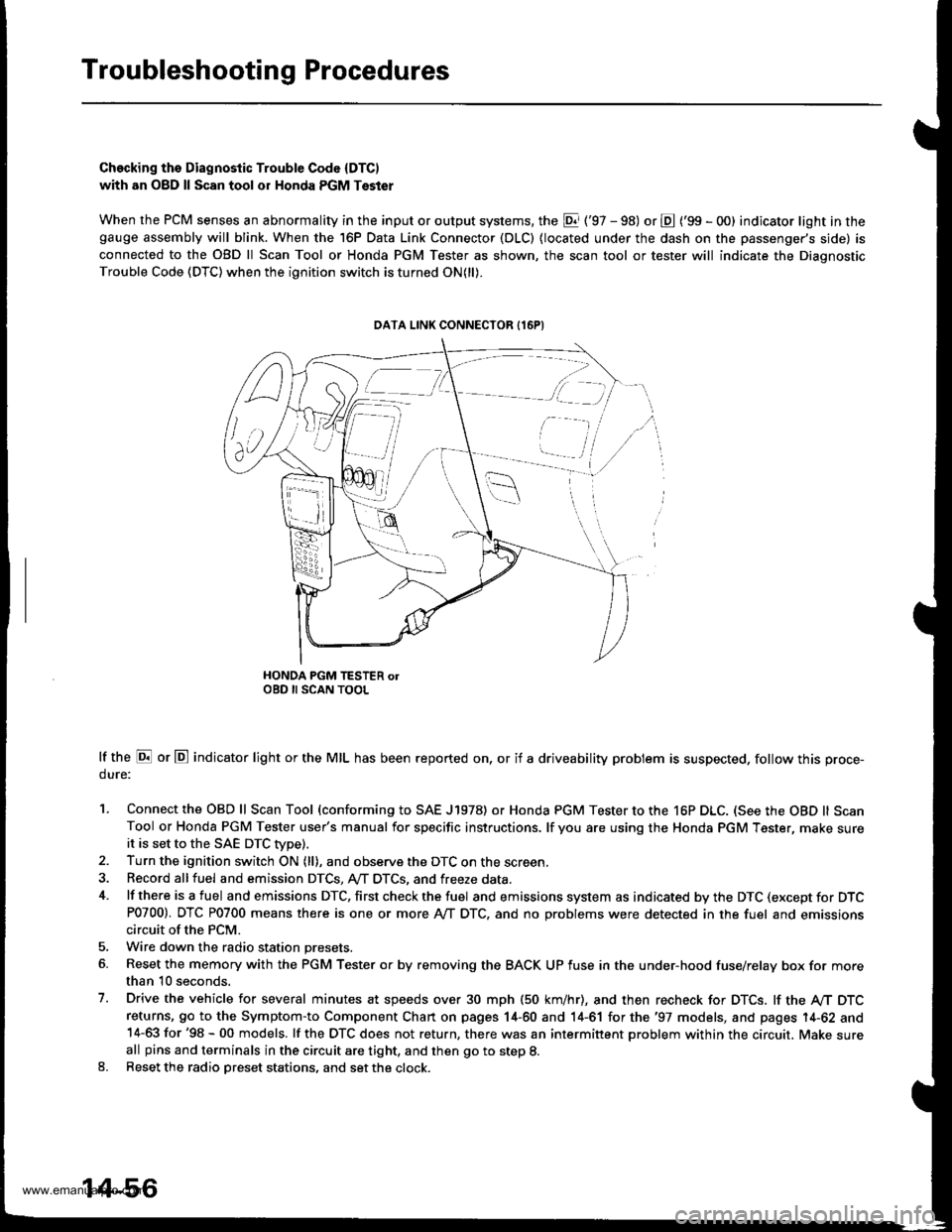
Troubleshooting Procedures
Checking ths Diagnostic Trouble Code (DTC)
with an O8D ll Scan tool or Honda PGM Tsster
When the PCM senses an abnormality in the input or output systems, the El ('97 - 98) or E ('99 - O0) indicator light in thegauge ass€mbly will blink. When the 16P Data Link Connector (DLC) {located under the dash on the passenger's side) is
connected to the OBD ll Scan Tool or Honda PGM Tester as shown, the scan tool or tester will indicate the Diagnostic
Trouble Code (DTC) when the ignition switch is turned ON(ll).
HONDA PGM TESTER olOBD II SCAN TOOL
lf the E or E indicator light or the MIL has been reported on, or if a driveability problem is suspected, follow this proce-
dure:
1. Connect the OBD ll Scan Tool (conforming to SAE J1978) or Honda PGM Tester to the 16P DLC. (See the OBD ll ScanTool or Honda PGM Tester user's manual for specific instructions. lf you are using the Honda PGM Tester, make sureit is set to the SAE DTC Wpe).2. Turn the ignition switch ON (ll), and observe the DTC on the screen
3. Record allfuel and emission DTCS, A,,/T DTCS, and freeze data.
4. lf there is a fuel and emissions DTC, first check the fuel and emissions system as indicated by the DTC (except for DTCP0700). DTC P0700 means there is one or more Ay'T DTC, and no Droblems were detected in the fuel and emissionscircuit of the PCM.
5. Wire down the radio station presets.
6. Reset the memory with the PGM Tester o. by removing the BACK UP fuse in the under-hood fuse/relay box for morethan 10 seconds.
7. Drive the vehicle for several minutes at speeds over 30 mph (50 km/hr), and then recheck for DTCS. lf the A/T DTCreturns, 9o to the Symptom-to Component Chart on pages 14-60 and 14-61 for the '97 models, and pages 14-62 and14-63 for '98 - 00 models. lf the OTC does not return, there was an intermittent problem within the circuit. Make sureall pins and terminals in the circuit are tight, and then go to step 8.8. Reset the radio Dreset stations, and set the clock.
DATA LINK CONNECTOR {16PI
[ -=.r,
ili,i /i,
v,., i
14-56
www.emanualpro.com
Page 573 of 1395
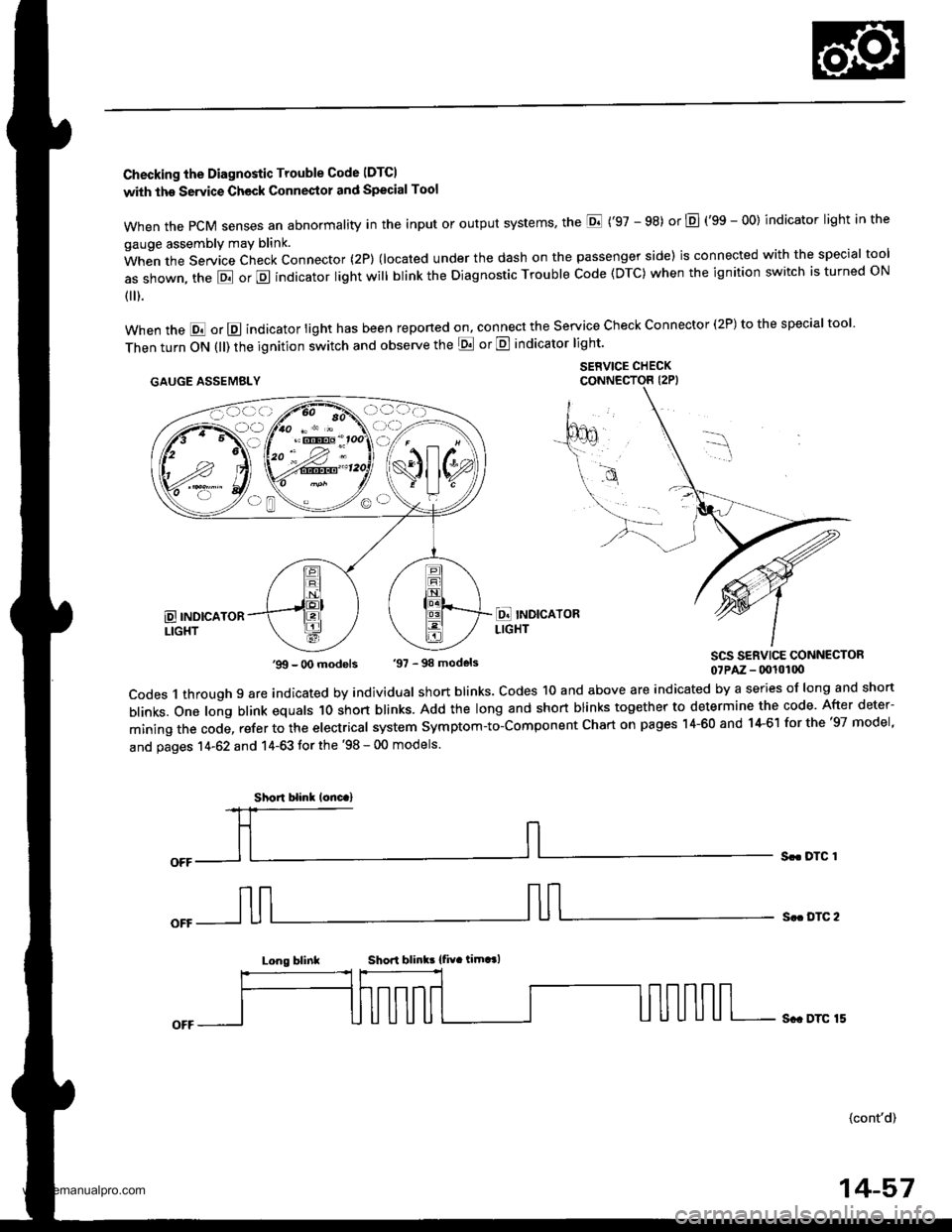
Checking the Diagnostic Trouble Code IDTCI
with the Servic€ Check Connestol and Special Tool
when the PcM senses an abnormality in the input or output systems' the E ('97 - 98) or E (gS - OO) indicator light in the
gauge assembly may blink.
When the Service Check Connector (2P) (located under the dash on the passenger side) is connected with the special tool
as shown, the E or E indicator light will blink the Diagnostic Trouble Code (DTC) when the ignition switch is turned ON
{ ).
when the E or E indicator light has been reponed on, connect the service check connector (2P) to the special tool
Then turn ON (ll) the ignition switch and observe the E or E indicator light'
.AUGE AssEMaLY $1,"^f:tT"'ff,
SCS SERVICE CONNECTOR07PAz - (x!l0100
codes 1 through 9 are indicated by individual short blinks. codes 1o and above are indicated by a series of long and short
blinks. one long blink equals 1o short blinks. Add the long and short blinks together to determine the code. After deter-
mining the code, refer to the electrical system symptom-to-component chart on pages 14-60 and 14-61 for the '97 model,
and pages 14-62 and 14-63 tor the '98 - 00 models.
Sr. DTC 1
S.. DTC 2
Long blinkShori blink! {fiv. timt l
Sc. DTC 15
(cont'd)
'99 - O0 models '97 - 98 models
Short blinl lonc.)
14-57
www.emanualpro.com