ESP HONDA CR-V 2000 RD1-RD3 / 1.G Owner's Manual
[x] Cancel search | Manufacturer: HONDA, Model Year: 2000, Model line: CR-V, Model: HONDA CR-V 2000 RD1-RD3 / 1.GPages: 1395, PDF Size: 35.62 MB
Page 1003 of 1395

Doors
Front and Rear Door Glass
Adiustment (cont'dl
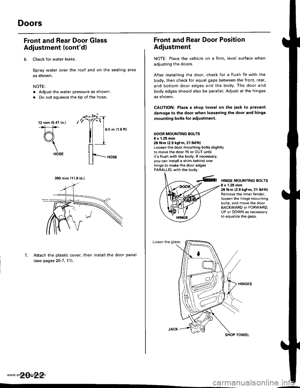
6. Check for water leaks.
Spray water over the roof and on the sealing area
as snown.
NOTE:
. Adjust the water pressure as shown.
. Do not soueeze the tio of the hose.
12 mm {0.47 in.l
#
(r\"1
HOSE
-"'*r"i
,'r)"f
tl
0.5 m (1.6 ftl
7. Attach the plastic cover, then install the door panel
(see pages 20-7, 'l 1),
20-22
..-
300 mm 111.8 in.)
Front and Rear Door Position
Adjustment
NOTE: Place the vehicle on a firm, level surface when
adiusting the doors.
After instailing the door, check for a flush fit with the
body, then check lor equal gaps between the front, rear.
and bottom door edges and the body. The door and
body edges should also be parallel. Adjust at the hinges
as shown.
CAUTION: Placa a shop towel on the iack to prevent
damage to the door when loosening the door and hinge
mounting bolts lor adiustment.
DOOR MOUNTING BOLTSI x 1.25 mm28 N.m 12.9 kgtr.m, 21 lbI.ftlLoosen the door mounting bolrs slighrlyto movethe door lN or OUT untilit's flush with the bodv. lf necessary,you can installa shim behind onehinge to make the door edgesPARALLEL with the bodv.
HINGE MOUNTING BOLTS8 x 1.25 mm28 N,m 12.9 kgt.m. 21 lbl.ftlRemove the inner fender,loosen the hinge mountingbolts, and move the doorBACKWARD or FORWARD,UP or DOWN as necessaryto equalize the gaps.
Lower the glass.
www.emanualpro.com
Page 1006 of 1395

Tailgate Door Striker Adjustment
Make sure the door latches securely without slamming
it. lf necessary, adjust the striker: The striker nuts are
fixed. The striker can be adjusted slightly up or down,
and in or out.
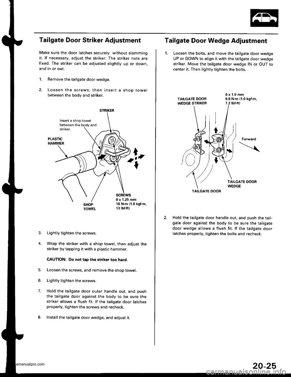
1. Remove the tailgate door wedge.
2. Loosen the screws, then insert a shop towel
between the body and striker.
8 x 1.25 mm18 N.m (1.8 kgf.m,r 3 tbf.ft)
1.
4.
Lightly tighten the screws.
Wrap the striker with a shop towel, then adjust the
striker by tapping it with a plastic hammer.
CAUTION: Do not tap the striker too hard.
Loosen lhe screws, and remove the shop towel.
Lightly tighten the screws.
Hold the tailgate door outer handle out, and push
the tailgate door against the body to be sure thestriker allows a flush fit. lf the tailgate door latchesproperly, tighten the screws and recheck.
Install the tailgate door wedge, and adjust it.
STRIKER
Insen a shoptowelbetween the body and
Tailgate Door Wedge Adjustment
1. Loosen the bolts, and move the tailgate door wedge
UP or DOWN to align it with the tailgate door wedge
striker. Move the tailgate door wedge lN or OUT to
center it. Then lightly tighten the bolts.
TAILGATE OOOR
Hold the tailgate door handle out, and push the tail-gate door against the body to be sure the tailgate
door wedge allows a flush fit. lf the tailgate door
latches properly, tighten the bolts and recheck.
Forward
20-25
www.emanualpro.com
Page 1164 of 1395

Troubleshooting
Tips and Precautions (cont'dl
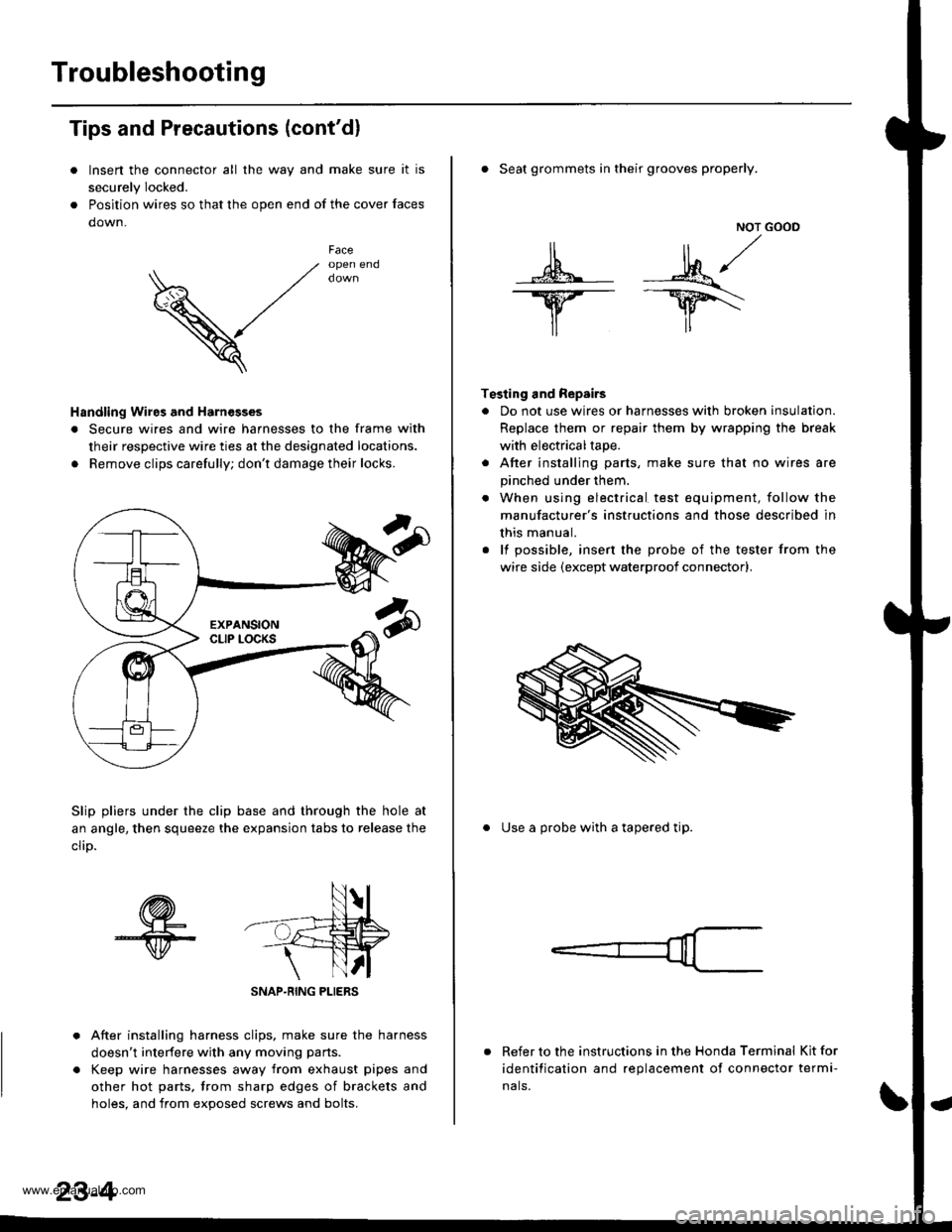
Insen the connector all the way and make sure it is
securely Iocked.
Position wires so that the open end of the cover faces
down.
V
Faceopen end
Handling Wires and Harnesges
. Secure wires and wire harnesses to the frame with
their respective wire ties at the designated locations.
. Remove clips carefully; don't damage their locks.
Slip pliers under the clip base and through the hole at
an angle, then squeeze the expansion tabs to release the
clrD.
After installing harness clips, make sure the harness
doesn't interfere with any moving pans.
Keep wire harnesses away from exhaust pipes and
other hot parts, trom sharp edges of brackets and
holes. and from exoos€d screws and bolts.
NOT GOOD
A -M/
lr lr*
T€sting and Repairs
. Do not use wires or harnesses with broken insulation.
Replace them or repair them by wrapping the break
with electricaltape.
. After installing parts, make sure that no wires are
pinched under them.
. When using electrical test equipment, follow the
manufacturer's instructions and those described in
this manual.
. lf possible, insert the probe of the tester from the
wire side (except waterproof connector).
. Seat grommets in their grooves properly.
. Use a probe with a tapered tip.
Refer to the instructions in the Honda Terminal Kit for
identification and replacement of connector termi-
nals.
www.emanualpro.com
Page 1314 of 1395

Description
J)
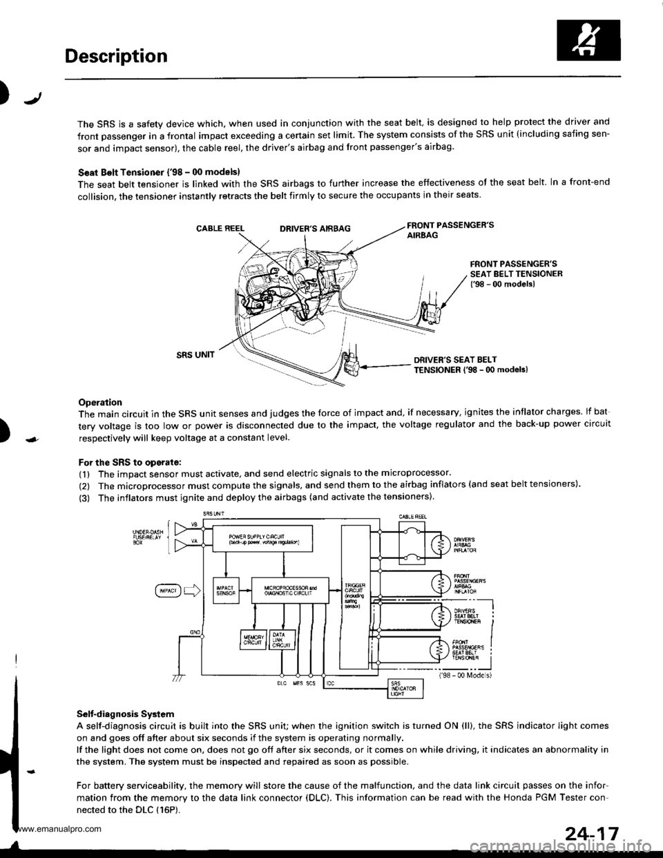
The SRS is a safety device which, when used in conjunction with the seat belt, is designed to help protect the driver and
front passenger in a frontal impact exceeding a certain set limit. The system consists of the SRS unit (including safing sen-
sor and impact sensor), the cable reel, the driver's airbag and front passenger's airbag.
Seat Bolt Tensioner {'98 - 00 models}
The seat belt tensioner is linked with the SRS airbags to further increase the effectiveness of the seat belt. In a front-end
collision, the tensioner instantly retracts the belt firmly to secure the occupants in their seats
FRONT PASSENGER'SAIREAGDRIVER'S AIRBAG
FRONT PASSENGER'SSEAT BELT TENSIONER{'98 - 00 modelsl
)
SRS UNITDRIVER'S SEAT BELTTENSIONER l'98 - 0O modeb)
Operation
The main circuit in the SRS unit senses and judges the force of impact and, if necessary, ignites the intlator charges. lf bat
tery voltage is too low or power is disconnected due to the impact, the voltage regulator and the back-up power circuit
respectively will keep voltage at a constant level.
For the SRS to operate:
(1) The impact sensor must activate, and send electric signals to the microprocessor.
(2) The microprocessor must compute the signals, and send them to the airbag inflators (and seat belt tensioners).
(3) The inflators must ignite and deploy the airbags (and activate the tensioners).
Selt-diagnosis System
A self-diagnosis circuit is built into the SRS uniU when the ignition switch is turned ON (ll), the SRS indicator Iight comes
on and goes off after about six seconds if the system is operating normally.
lf the light does not come on, does not go off after six seconds, or it comes on while driving, it indicates an abnormality in
the system. The system must be inspected and repaired as soon as possible.
For battery serviceability, the memory will store the cause of the malfunction, and the data link circuit passes on the infor
mation from the memory to the data link connector (DLC). This information can be read with the Honda PGM Tester con-
nected to the DLC {16P).
198
---__-l
TENSTO1En II
_-___J- 00 N4ode s)
24-17
www.emanualpro.com