Door HONDA CR-V 2000 RD1-RD3 / 1.G Owner's Guide
[x] Cancel search | Manufacturer: HONDA, Model Year: 2000, Model line: CR-V, Model: HONDA CR-V 2000 RD1-RD3 / 1.GPages: 1395, PDF Size: 35.62 MB
Page 999 of 1395
Doors
Tailgate Door Latch and Latch Stop
Replacement (cont'd)
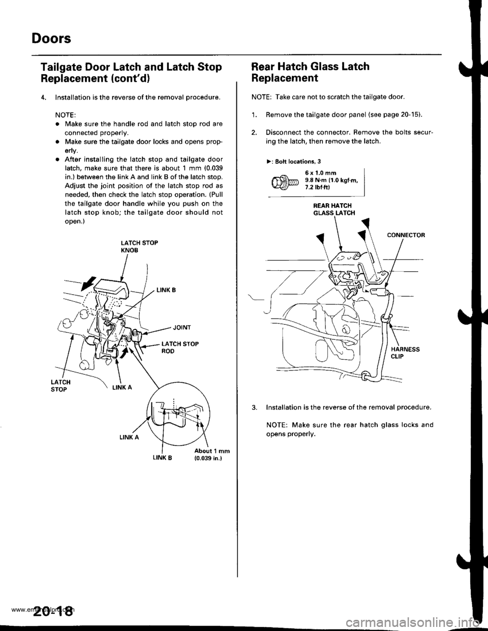
4. lnstallation is the reverse of the removal orocedure.
NOTE:
. Make sure the handle rod and latch stop rod are
connected properly.
a Make sure the tailgate door locks and opens prop-
env.
. After installing the latch stop and tailgate door
latch, make sure that there is about 1 mm {0.039
in.l between the link A and link B of the latch stop.
Adjust the joint position of the latch stop rod as
needed, then check the latch stop operation. (Pull
the tailgate door handle while you push on the
latch stop knob; the tailgate door should not
oDen.)
LATCH STOPKNOE
20-18
Rear Hatch Glass Latch
Replacement
NOTE: Take care not to scratch the tailgate door.
'1. Remove the tailgate door panel (seepage20-15).
2. Disconnect the connector. Remove the bolts secur-
ing the latch, then remove the latch.
>: Boh locations, 3
6x1.0mm9.8 N.m {1.0 kgI.m,7.2 tbl.Itl
REAR HATCHGLASS LATCH
3. Installation is the reverse of the removal procedure.
NOTE: Make sure the rear hatch glass locks and
opens properly.
www.emanualpro.com
Page 1000 of 1395
Rear Hatch Glass Lock Cylinder
Replacement
NOTE: Take care not to scratch the tailgate door.
1. Remove the tailgate door panel (see page 20-15).
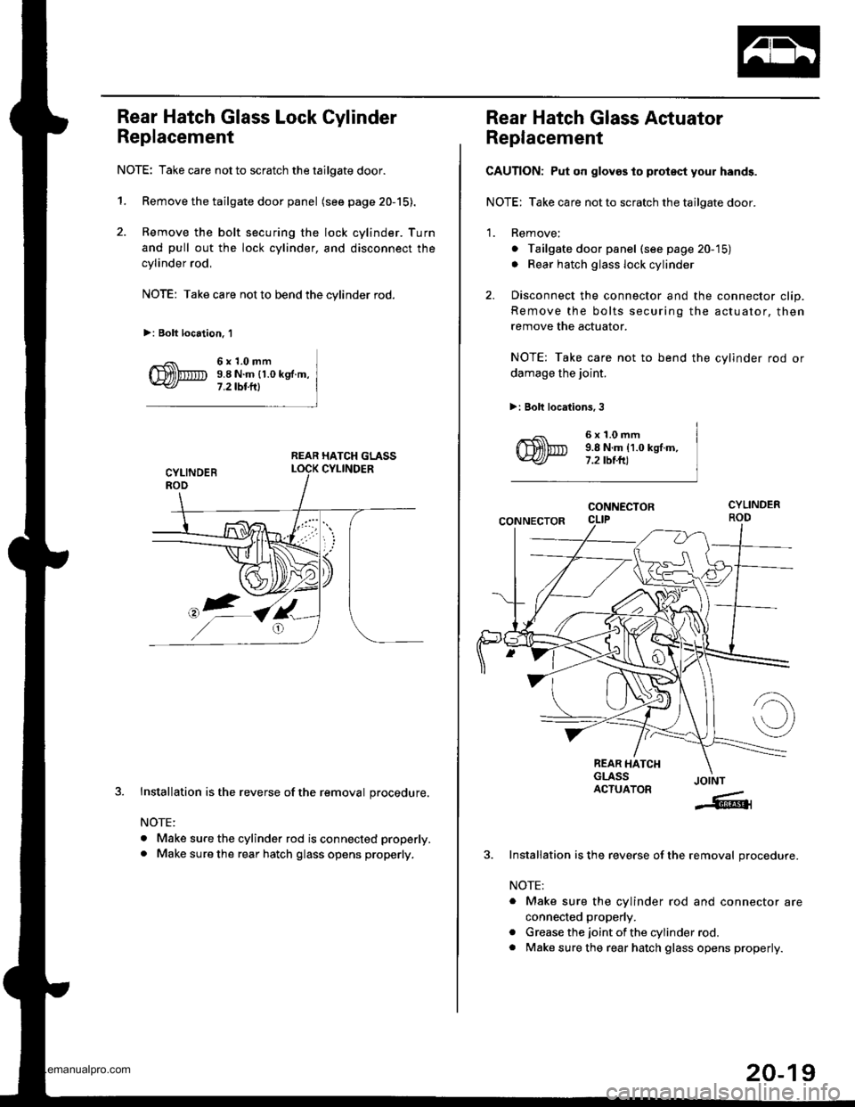
2. Remove the bolt securing the lock cylinder. Turn
and pull out the lock cylinder, and disconnect the
cylinder rod,
NOTE: Take care not to bend the cylinder rod.
>: Bolt location. 1
6x1.0mm9.8 N.m {1.0 kg .m,
7 .2 tbt.lll
REAR HATCH GLASS
J.Installation is the reverse of the removal procedure.
NOTE:
. Make sure the cylinder rod is connected properly.
. Make sure the rear hatch glass opens properly.
Rear Hatch Glass Actuator
Replacement
CAUTION: Put on gloves to protsct your hands.
NOTE: Take care not to scratch the tailgate door.
1. Remove;
o Tailgate door panel (see page 20-'15)
. Rear hatch glass lock cylinder
2. Disconnect the connector and the connector clip.
Remove the bolts securing the actuator, then
remove the actuator.
NOTE: Take care not to bend the cylinder rod or
damage the joint.
>: Bolt locations, 3
6x1.0mm9.8 N.m 11.0 kgt.m,7.2 tbt.ft)
CONNECTOR
CONNECTOR
REAR HATCHGLASSACTUATORJOINT
-6{
Installation is the reverse of the removal procedure.
NOTE:
. Make sure the cylinder rod and connector are
connected properly.
. Grease the joint of the cylinder rod.
. Make sure the rear hatch glass opens properly.
20-19
www.emanualpro.com
Page 1001 of 1395
Doors
Tailgate Door Weatherstrip
Replacement
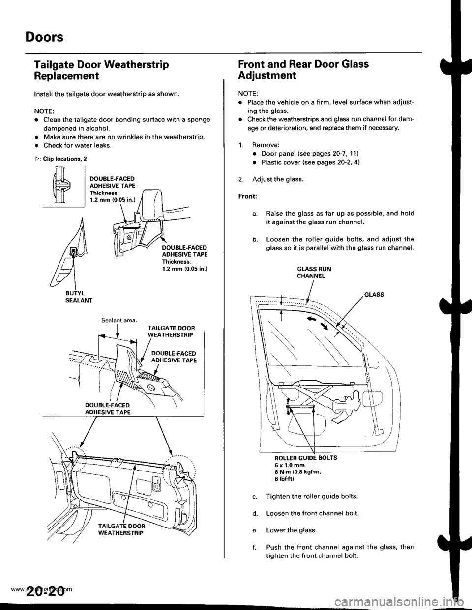
Install the tailgate door weatherstrip as shown.
NOTE;
. Clean the tailgate door bonding surface with a sponge
dampened in alcohol.
Make sure there are no wrinkles in the weatherstrip.
Check for water leaks.
Clip locations, 2
a
a
>:
i-t] |
/[L I oouere-rrceo
lE I aDHEsrvE rAPE
ll 1T I Thickness:
lll I r.2 mm lo.o5 in.)
A
lM
/L)
g\
BUTYLSEALANT
DOUBLE.FACEDADHESIVE TAPEThickne$:1.2 mm 10.05 in.)
Sealant area,
20-20
Front and Rear Door Glass
Adjustment
NOTE:
. Place the vehicle on a firm, level surface when adjust-
ing the glass.
. Check the weatherstrips and glass run channel for dam-
age or deterioration, and replace them if necessary,
1. Remove:
. Door panel (see pages20-7, lll
. Plastic cover (see pages2O-2,41
2. Adjust the glass.
Front:
Raise the glass as far up as possible. and hold
it against the glass run channel.
Loosen the roller guide bolts, and adjust the
glass so it is parallel with the glass run channel.
GLASS RUNCHANNEL
ROLLER GUIDE BOLTS6x1.0mm8 N.m {0.8 kgf.m,5 tbffi)
Tighten the roller guide bolts.
Loosen the front channel bolt.
Lower the glass.
Push the front channel against the glass, then
tighten the tront channel bolt.
e.
l.
www.emanualpro.com
Page 1003 of 1395
Doors
Front and Rear Door Glass
Adiustment (cont'dl
6. Check for water leaks.
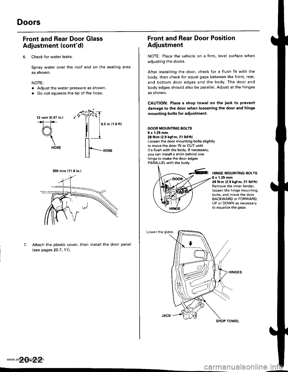
Spray water over the roof and on the sealing area
as snown.
NOTE:
. Adjust the water pressure as shown.
. Do not soueeze the tio of the hose.
12 mm {0.47 in.l
#
(r\"1
HOSE
-"'*r"i
,'r)"f
tl
0.5 m (1.6 ftl
7. Attach the plastic cover, then install the door panel
(see pages 20-7, 'l 1),
20-22
..-
300 mm 111.8 in.)
Front and Rear Door Position
Adjustment
NOTE: Place the vehicle on a firm, level surface when
adiusting the doors.
After instailing the door, check for a flush fit with the
body, then check lor equal gaps between the front, rear.
and bottom door edges and the body. The door and
body edges should also be parallel. Adjust at the hinges
as shown.
CAUTION: Placa a shop towel on the iack to prevent
damage to the door when loosening the door and hinge
mounting bolts lor adiustment.
DOOR MOUNTING BOLTSI x 1.25 mm28 N.m 12.9 kgtr.m, 21 lbI.ftlLoosen the door mounting bolrs slighrlyto movethe door lN or OUT untilit's flush with the bodv. lf necessary,you can installa shim behind onehinge to make the door edgesPARALLEL with the bodv.
HINGE MOUNTING BOLTS8 x 1.25 mm28 N,m 12.9 kgt.m. 21 lbl.ftlRemove the inner fender,loosen the hinge mountingbolts, and move the doorBACKWARD or FORWARD,UP or DOWN as necessaryto equalize the gaps.
Lower the glass.
www.emanualpro.com
Page 1004 of 1395
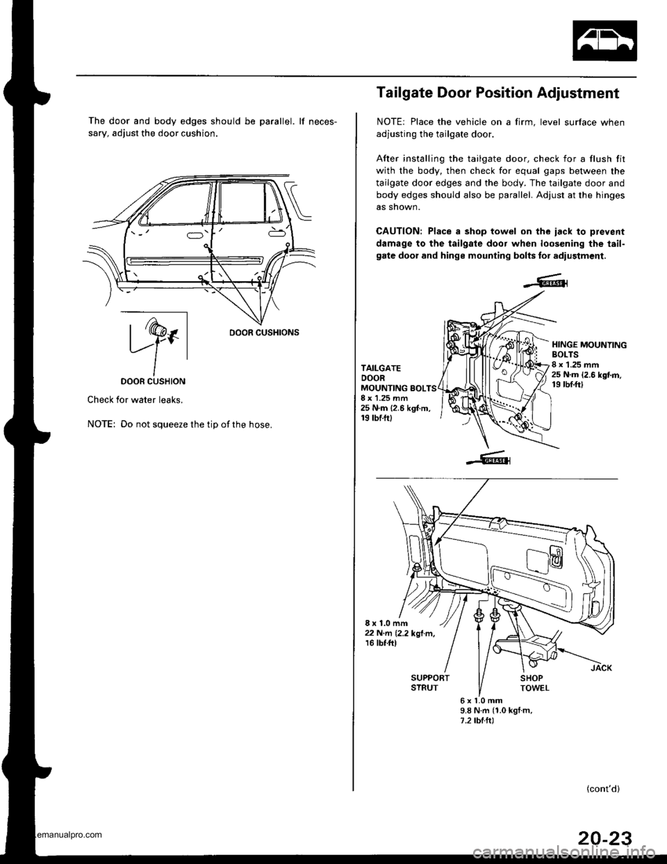
The door and body edges should be parallel. lf neces-
sary, adjust the door cushion.
ry.DOOR CUSHION
Check for water leaks.
NOTE: Do not squeeze the tip ofthe hose.
oooR cusHroNs
Tailgate Door Position Adjustment
NOTE: Place the vehicle on a firm, level surface when
adjusting the tailgate door.
After installing the tailgate door. check for a flush fit
with the body, then check for equal gaps between the
tailgate door edges and the body. The tailgate door and
body edges should also be parallel. Adjust at the hinges
as snown.
CAUTION: Place a shop towel on the iack lo prevent
damage to the tailgale door when loos€ning the tail-
gate door and hinge mounting bolts for adiustment.
TAILGATEDOORMOUNTING sOLTS8 x 1.25 mm25 N.m {2.6 kgf.m,19 tbf.ft)
HINGE MOUNYINGBOLTS8 x 1.25 mm25 N.m 12.6 kgt m,19 rbf.ftl
8x1.0mm22 N'rrl� 12.2 kgl.m,16 tbt.ftl
6xl.0mm9.8 N.m {1.0 kgt m,1.2 tbl.ltl
(cont'd)
20-23
www.emanualpro.com
Page 1005 of 1395
Doors
(cont'd)
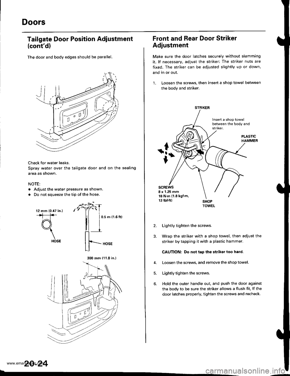
The door and body edges should be parallel.
Check for water leaks.
Spray water over the tailgate door and on the sealing
area as shown.
NOTE:
. Adjust the water pressure as shown.
. Do not squeeze the tip ofthe hose.
Tailgate Door Position Adiustment
-€*4
,'r)"C
II
0.5 m {1.6 ft}
20-24
l2 mm (0.47 in.).*1:]*
d3"1
HOSE
300 mm {11.8 in.l
Front and Rear Door Striker
Adjustment
Make sure the door latches securely without slamming
it, lf necessary, adjust the striker: The striker nuts are
fixed. The striker can be adjusted slightly up or down,
and in or out.
1. Loosen the screws, then insert a shop towel between
the body and striker.
Insert a shop towelbetween the body and
scREws8 x 1 .25 mm18 N.m (1.8 kgt.m,13 rbf.ft)
2.
J.
Lightly tighten the screws.
Wrap the striker with a shop towel, then adjust the
striker by tapping it with a plastic hammer.
CAUTION: Do not tap the striksr loo hard.
Loosen the screws. and remove the shop towel.
Lightly tighten the screws.
Hold the outer handle out, and push the door against
the body to be sure the striker allows a flush fit, lf the
door latches properly. tighten the screws and recheck.
4.
5.
6.
STRIKER
www.emanualpro.com
Page 1006 of 1395
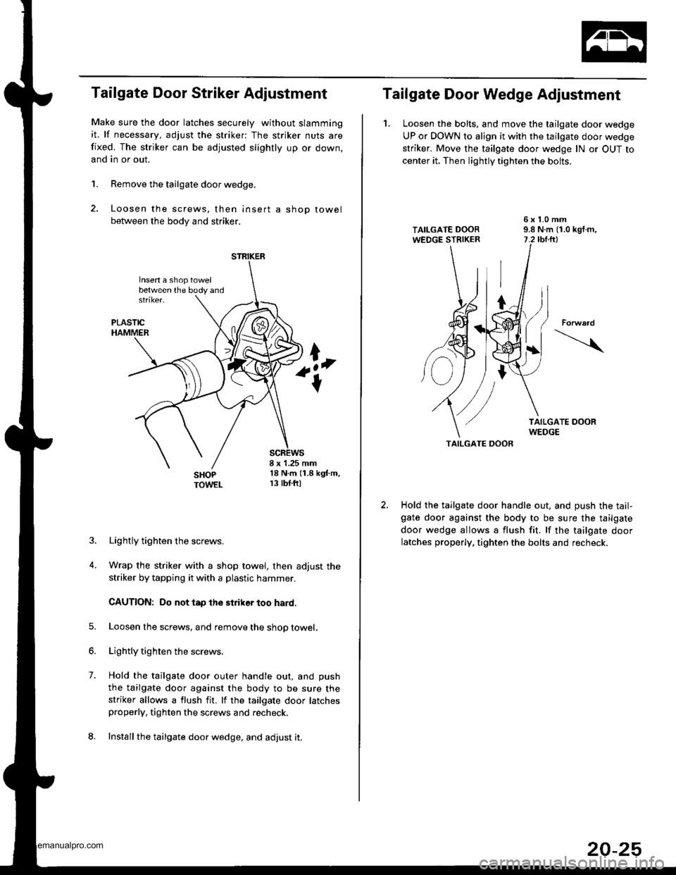
Tailgate Door Striker Adjustment
Make sure the door latches securely without slamming
it. lf necessary, adjust the striker: The striker nuts are
fixed. The striker can be adjusted slightly up or down,
and in or out.
1. Remove the tailgate door wedge.
2. Loosen the screws, then insert a shop towel
between the body and striker.
8 x 1.25 mm18 N.m (1.8 kgf.m,r 3 tbf.ft)
1.
4.
Lightly tighten the screws.
Wrap the striker with a shop towel, then adjust the
striker by tapping it with a plastic hammer.
CAUTION: Do not tap the striker too hard.
Loosen lhe screws, and remove the shop towel.
Lightly tighten the screws.
Hold the tailgate door outer handle out, and push
the tailgate door against the body to be sure thestriker allows a flush fit. lf the tailgate door latchesproperly, tighten the screws and recheck.
Install the tailgate door wedge, and adjust it.
STRIKER
Insen a shoptowelbetween the body and
Tailgate Door Wedge Adjustment
1. Loosen the bolts, and move the tailgate door wedge
UP or DOWN to align it with the tailgate door wedge
striker. Move the tailgate door wedge lN or OUT to
center it. Then lightly tighten the bolts.
TAILGATE OOOR
Hold the tailgate door handle out, and push the tail-gate door against the body to be sure the tailgate
door wedge allows a flush fit. lf the tailgate door
latches properly, tighten the bolts and recheck.
Forward
20-25
www.emanualpro.com
Page 1008 of 1395
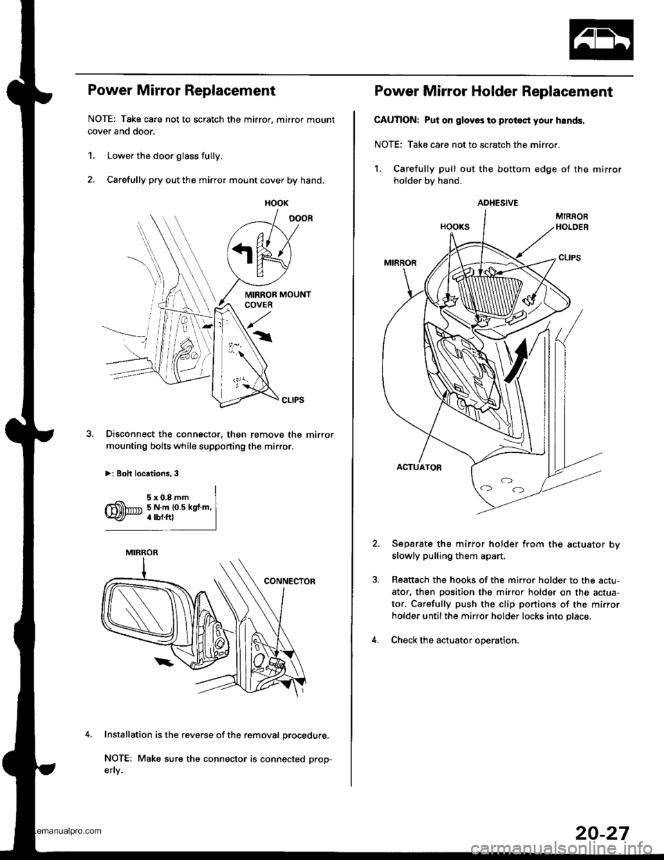
Power Mirror Replacement
NOTE: Tako care not to scratch the mirror, mirror mount
cover and door.
1. Lower the door glass fully.
2. Carefully pry out the mirror mount cover by hand,
,l
Disconnect the connector. then remove the mirror
mounting bolts while supponing the mirror,
>: Boh locations, 3
Installation is the reverse of the removal procedure,
NOTE: Make sure the connector is connected prop-
efly.
HOOK
MIRROR
Power Mirror Holder Replacement
CAUTION: Put on glovss to protest you. hands.
NOTE: Take care not to scratch the mirror.
1, Carefully pull out the bottom edge of the mirror
holder bv hand.
Separate the mirror holder from the actuator bv
slowly pulling them apart.
Reattach the hooks of the mirror holder to the actu-
ator, then Dosition the mirror holder on the actua-
tor. Carefully push the clip portions of the mirror
holder untilthe mirror holder locks into place.
Check the actuator ooeration.
ADHESIVE
20-27
www.emanualpro.com
Page 1011 of 1395
Glass
Windshield Replacement
CAUTION:
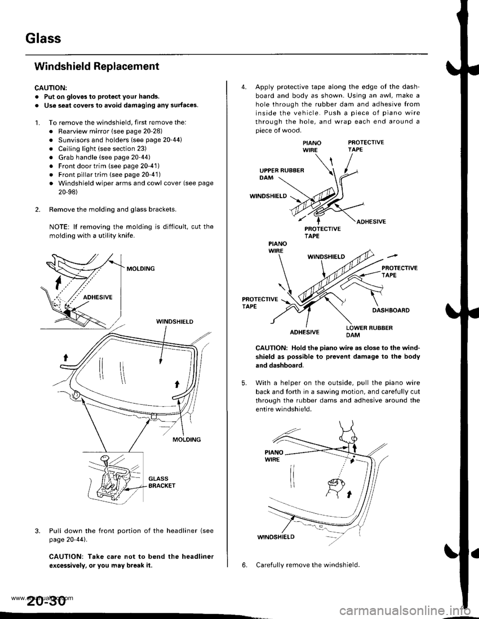
. Put on gloves to protect your hands.
. Use seat covers to avoid damaging any surfaces.
1. To remove the windshield, first remove the:
. Rearview mirror (see page 20-28)
. Sunvisors and holders (see page 20-44l'
. Ceiling light (see section 23)
. Grab handle (see page 20-44)
. Front door trim (see page 20-41)
. Front pillar trim (see page 20-41)
. Windshield wiper arms and cowl cover (see page
20-98)
2. Remove the molding and glass brackets.
NOTE: lf removing the molding is difficult, cut the
moldlng with a utility knife.
MOLDING
3. Pull down the front Dortion of the headliner (see
page 20-44).
CAUTION: Take care not to bend the headliner
excessivsly, or you may break it.
WINDSHIELD
20-30
4. Apply protective tape along the edge ot the dash-
board and body as shown. Using an awl, make a
hole through the rubber dam and adhesive from
inside the vehicle. Push a piece of piano wire
through the hole, and wrap each end around a
piece of wood.
PROTECTIVETAPE
WINDSHIELD
ADHESIVE
PIANOWIRE
PROTECTIVETAPE
WINDSHIELO
PROTECTIVETAPEDASHBOARD
ADHESIVELOWER RUBBERDAM
CAUTION: Hold the piano wire as close to the wind-
shield as possible to prevent damage to the body
and dashboard.
5. With a helper on the outside, pull the piano wire
back and fo(h in a sawing motion, and carefully cut
through the rubber dams and adhesive around the
entire windshield.
6. Carefully remove the windshield.
UPPER RUBBER
PIANO
www.emanualpro.com
Page 1016 of 1395
22.
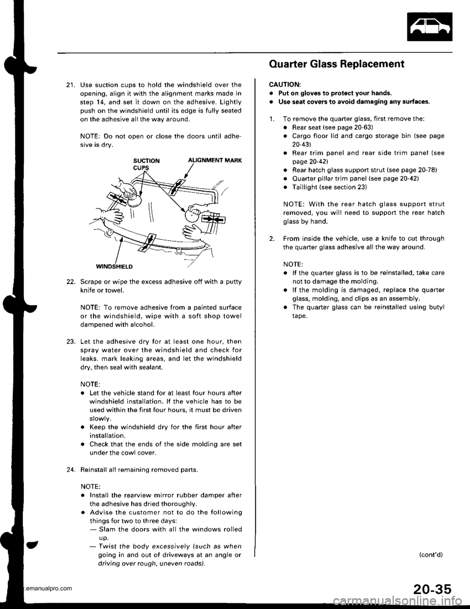
21. Use suction cups to hold the windshield over the
opening, align it with the alignment marks made in
step 14, and set it down on the adhesive. Ljghtly
push on the windshield until its edge is fully seated
on the adhesive all the way around.
NOTEr Do not open or close the doors until adhe-
sive is dry.
SUCTTON ALIGNMENT MARK
Scrape or wipe the excess adhesive off with a putty
knife or towel.
NOTE: To remove adhesive from a painted surface
or the windshield, wipe with a soft shop towel
dampened with alcohol.
Let the adhesive dry for at least one hour, then
spray water over the windshield and check for
leaks. mark leaking areas, and let the windshield
dry, then seal with sealant.
NOTE:
. Let the vehicle stand for at least four hours after
windshield installation. lf the vehicle has to be
used within the first four hours, it must be driven
. Keep the windshield dry for the first hour after
installation.
. Check that the ends of the side molding are set
under the cowl cover.
Reinstall all remaining removed parts.
NOTE:
. Install the rearview mirror rubber damper after
the adhesive has dried thoroughl,.
. Advise the customer not to do the following
things for two to three days:- Slam the doors with all the windows rolled
up.- Twist the body excess,vely {such as when
going in and out of driveways at an angle or
driving over rough. uneven roads).
24.
Ouarter Glass Replacement
CAUTION:
. Put on gloves to prot€ct your hands.
. Use seat covers to avoid damaging any surfaces.
1. To remove the quarter glass, first remove the:
. Rear seat (see page 20-63)
. Cargo floor lid and cargo storage bin (see page
20 431
. Rear trim panel and rear side trim panel (see
page 20-421
. Rear hatch glass support strut (see page 20-78)
. Ouarter pillar trim panel (see page20-421
. Taillight (see section 23)
NOTE: With the rear hatch glass support strut
removed, you will need to support the rear hatch
glass by hand.
2. From inside the vehicle, use a knife to cut through
the quarter glass adhesive all the way around.
NOTE:
. lf the quaner glass is to be reinstalled, take care
not to damage the molding.
. lf the molding is damaged. replace the quarter
glass, molding, and clips as an assembly.
. The quarter glass can be reinstalled using butyl
tape.
(cont'd)
20-35
www.emanualpro.com