Gasket HONDA CR-V 2000 RD1-RD3 / 1.G Owner's Guide
[x] Cancel search | Manufacturer: HONDA, Model Year: 2000, Model line: CR-V, Model: HONDA CR-V 2000 RD1-RD3 / 1.GPages: 1395, PDF Size: 35.62 MB
Page 507 of 1395
Transmission Assembly
Reassembly (cont'dl
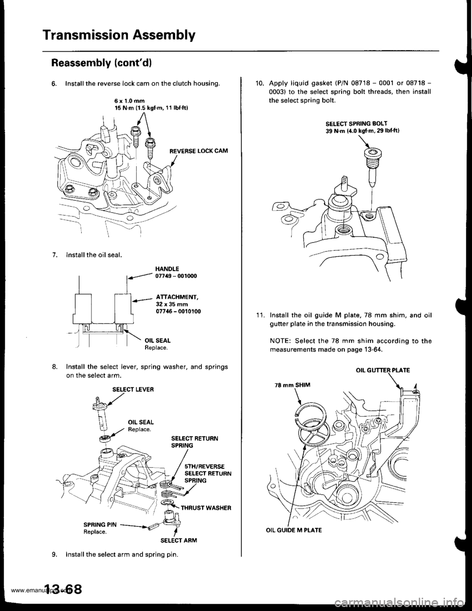
6. Installthe reverse lock cam on the clutch housing.
6x1.0mm15 N.m (1.5 kgf.m, 11 lbf.ftl
REVERSE LOCK CAM
7. lnstall the oil seal.
HANDLE07749 - 001mO
ATTACHMENT,32x35mm07745 - 0010100
OIL SEALReplace.
Install the select lever, spring washer, and springs
on the select arm.
SELECT LEVER
SELECT BETURNSPRING
5TH/REVERSESELECT RETURN
SPRING PINReplace.
SELECT ARM
9. Installthe select arm and spring pin.
13-68
10. Apply liquid gasket (P/N 08718 - 0001 or 08718 -
0003) to the select spring bolt threads, then install
the select spring bolt.
SELECT SPRING BOLT
39 N.m la.o kgf'm,29lbtft)
'I 1.Install the oil guide M plate.78 mm shim, and oil
guner plate in the transmission housing.
NOTE: Select the 78 mm shim according to the
measurements made on page 13-64,
OIL GUIDE M PLATE
www.emanualpro.com
Page 508 of 1395
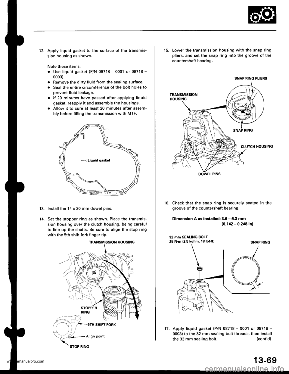
12. Apply liquid gasket to the surface of the transmis-
sion housing as shown.
Note these items:
. Use liquid gasket (P/N 08718 - 0001 or 08718 -
0003).
. Remove the dirty fluid from the sealing surface.
. Seal the entire circumterence of the bolt holes to
prevent fluid leakage.
. lf 20 minutes have passed after applying liquid
gasket, reapply it and assemble the housings.
a Allow it to cure at least 20 minutes after assem-
bly betore filling the transmission with MTF.
Install the 14 x 20 mm dowel pins.
Set the stopper ring as shown. Place the transmis-
sion housing over the clutch housing, being careful
to line up the shafts. Be sure to align the stop ring
with the 5th shift fork finger tip.
r3.
14.
TRANSMISSION HOUSING
SHIFT FORK
vk..*,
Align point
17.
the 32 mm sealing bolt.
15. Lower the transmission housing with the snap ring
pliers. and set the snap ring into the groove of the
countershaft bearing.
Check that the snap ring is securely seated in the
groove of the countershaft bearing.
Dimension A as installod: 3.6 - 6.3 mm
(0.142 - 0.2/8 in)
16.
32 mm SEALING BOLT25 N m 12.5 kgf.m, 18 lbf.ftlSNAP RING
(cont'd)
13-69
Apply liquid gasket (P/N 08718 - 0001 or 08718 -
0003) to the 32 mm sealing bolt threads, then install
SNAP RING PLIERS
DOWEL PINS
www.emanualpro.com
Page 510 of 1395
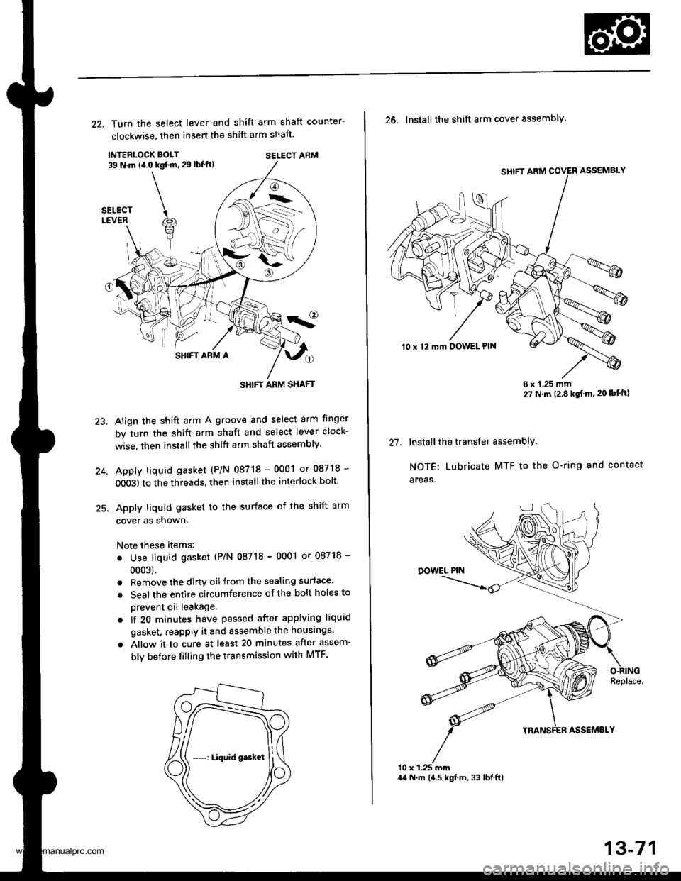
22. Turn the select lever and shift arm shaft counter-
clockwise, then insert the shift arm shaft.
INTERLOCK EOLT39 N.m (4.0 kqt ft, 29 lbf ft)SELECT ARM
SHIFT ARM A
Align the shift arm A groove and select arm finger
by turn the shift arm shaft and select lever clock-
wise. then installthe shift arm shaft assembly.
Apply liquid gasket (P/N 08718 - 0001 or 08718 -
OO03) to the threads, then install the interlock bolt'
Apply liquid gasket to the surface of the shift arm
cover as snown.
Note these items:
. Use liquid gasket (P/N 08718 - 0001 or 08718 -
0003).
. Remove the dirtv oilfrom the sealing surface.
. Seal the entire circumference of the bolt holes to
prevent oil leakage.
. lf 20 minutes have passed after applying liquid
gasket. reapply it and assemble the housings.
a Allow it to cure at least 20 minutes after assem-
bly betore filling the transmission with MTF.
23.
-->.-
(
SHIFT ARM SHAFT
SHIFT ARM COVER ASSEMBLY
10 x 12 mft DOWEL PIN
t1
26. Install the shift arm cover assembly.
I x 1.25 mm27 N m 12.8 kgt m,20 lbf'ft)
Install the transfer assemblY.
NOTE: Lubricate MTF to the O-ring and contact
areas.
10 x 1.25 mm44 N.m 14.5 kgf.m, 33 lbl.ftl
13-71
www.emanualpro.com
Page 513 of 1395
Transmission Assembly
Installation (cont'dl
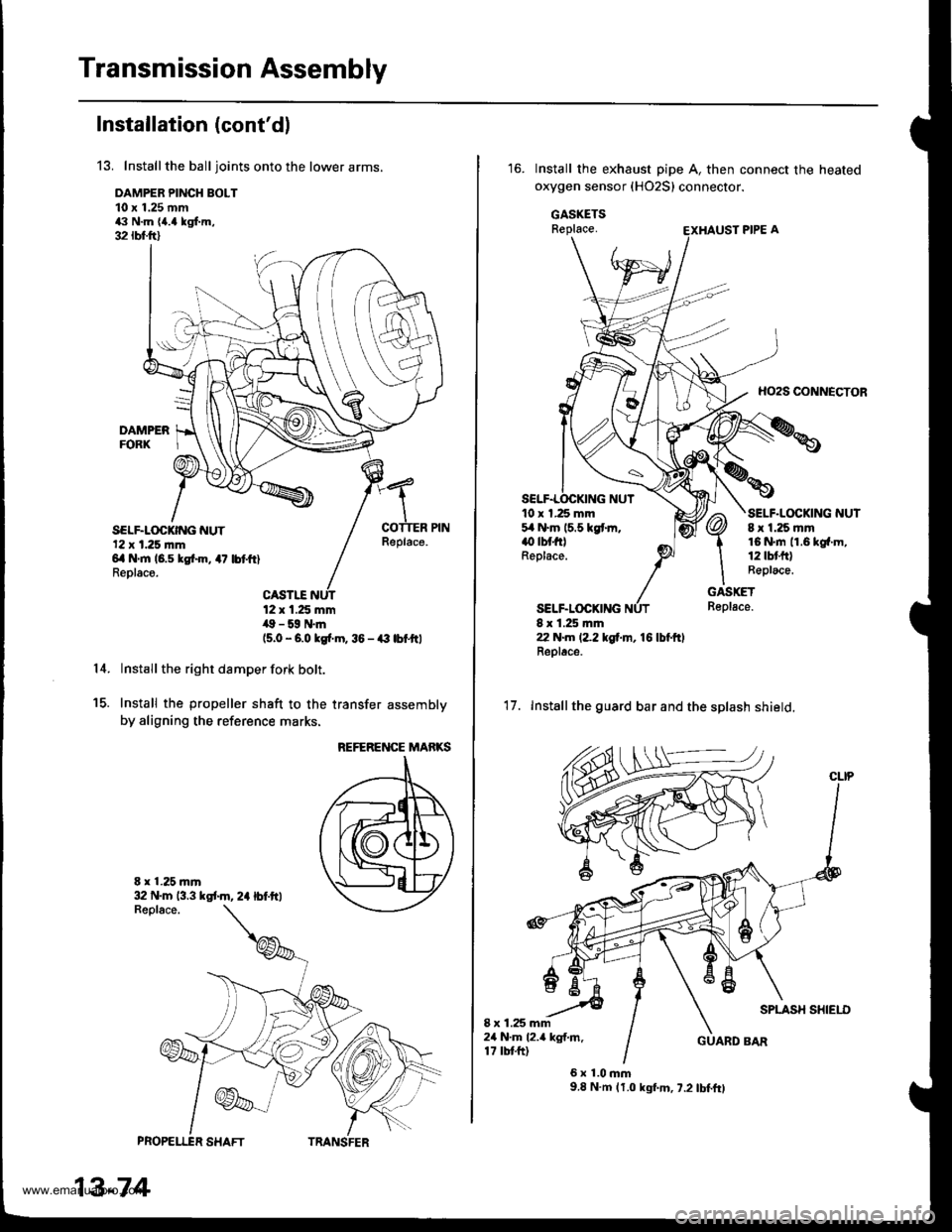
13. Installthe balljoints onto the lower arms.
DAMPER PINCH BOLT10 x 1.25 mm43 N.m {a.a kgf.m,32 rbfft)
SELF.LOCKING NUT'12 x 1.25 |nm6il N'm 16.5 kgtin, 47 lbtftlReolace.
Replace.
14.
PROPELI"ER SHAFT
13-74
12 x 1.25 mm,19 - 59 N.m(5.0 - 6.0 kgi.m, 36 - € lbfttl
Install the right damper fork bolt.
Install the propeller shaft to the transfer assembly
by aligning the reference marks.
E x 1.25 mr'|
15.
REFERENCE MARKS
32 N.m 13.3 kst m, 2a lbf.ftl
TRANSFER
Install the exhaust pipe A, then connect the heated
oxygen sensor (HO2S) connector.
GASKETSReplace.
HO2S CONNECTOR
10 x 1.25 mm5,1N.m 15.5 kgtm.() tbt filReplace.
SELF.LOCKING
SELF.LOCKING NUT8 x 1.25 mm16 N.rn 11.6 kg{.m,12lbtfr)Replace.
GASKETReplace.
8 x 1.25 rr|ln22 N.m (2.2 tgf.m, 16 lbl.ftlReplac6.
'17. Installthe guard bar and the splash shield.
SPLASH SHIEI.I)I x 1.25 mm24 N.m l2.a kgf.m.17 tbtft)GUARD BAR
6x1.0mm9.8 N.m (1.0 kgf.m, 7.2 lbf.ft)
www.emanualpro.com
Page 651 of 1395
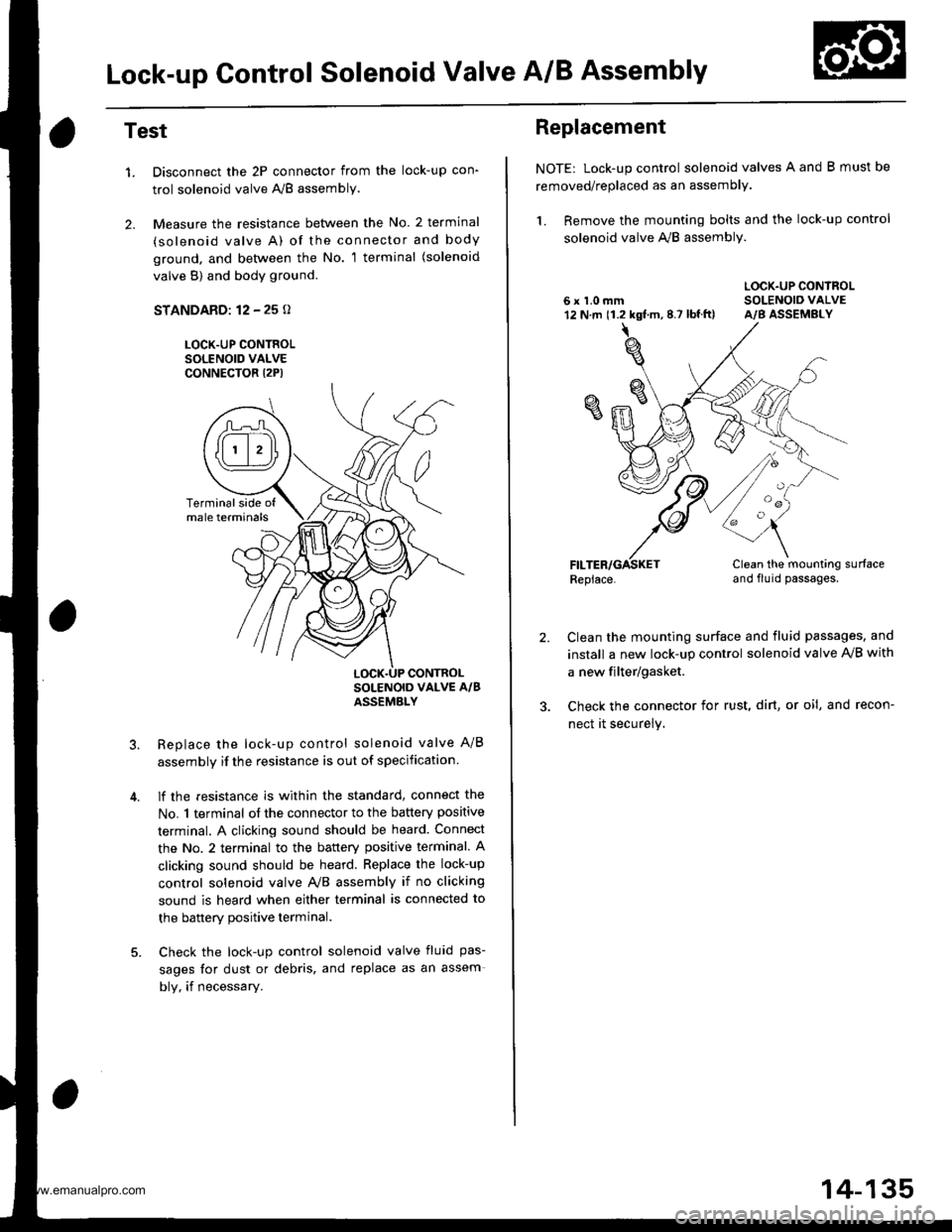
Lock-up Control Solenoid Valve A/B Assembly
Test
1.
2.
Disconnect the 2P connector from the lock-up con'
trol solenoid valve A'lB assembly.
Measure the resistance between the No. 2 terminal
(solenoid valve A) of the connector and body
ground. and bet\iveen the No. 1 terminal (solenoid
valve B) and body ground.
STANDARD: 12 - 25 o
LOCK-UP CONTROLSOLENOID VALVECONNECTOR I2P)
Replace the lock-up control solenoid valve A/B
assembly if the resistance is out of specification
lf the resistance is within the standard, connect the
No. 1 terminal of the connector to the battery positive
terminal. A clicking sound should be heard Connect
the No. 2 terminal to the battery positive terminal. A
clicking sound should be heard. Replace the lock-up
control solenoid valve Ay'B assembly if no clicking
sound is heard when either terminal is connected to
the banerv Dositive terminal.
Check the lock-up control solenoid valve fluid pas-
sages for dust or debris, and replace as an assem
bly, if necessary.
Terminalside ofmale terminals
LOCK.UP CONTROL
Replacement
NOTE: Lock-up control solenoid valves A and B must be
removed/replaced as an assembly.
1. Remove the mounting bolts and the lock-up control
solenoid valve A,,/B assembly.
LOCK.UP CONTROL6 x 1.0 mm SOLENOIO VALVE12 N.m 11.2 kgf.m,8.7 lbf.ft) A/B ASSEMBLY
Replace.Clean the mounting surfaceand flu id passages.
2.Clean the mounting surface and fluid passages, and
install a new lock-up control solenoid valve IVB with
a new filter/gasket.
Check the connector for rust, dirt, or oi!, and recon-
nect it securely.
oa
14-135
www.emanualpro.com
Page 652 of 1395
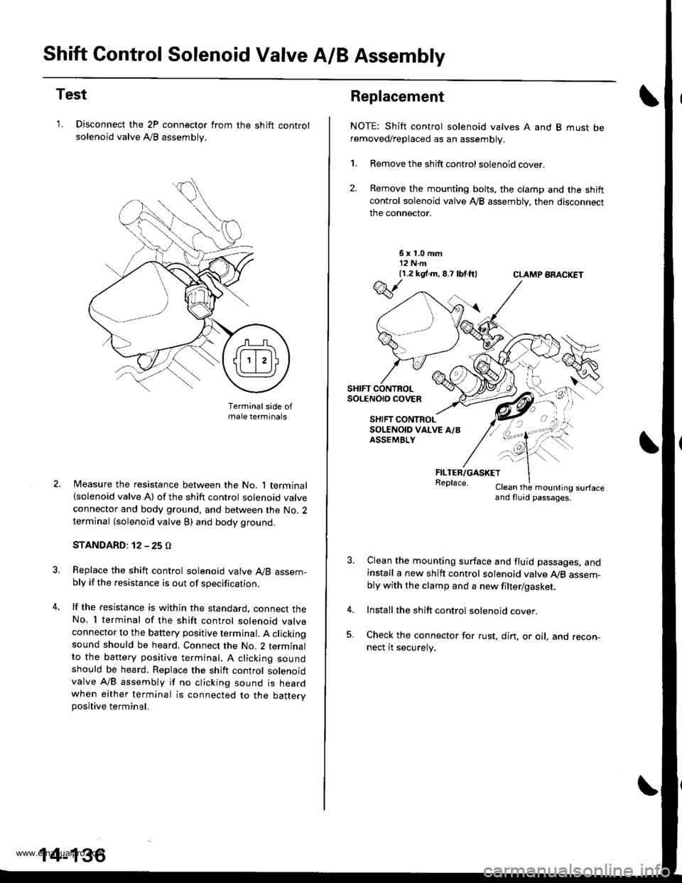
Shift Control Solenoid Valve A/B Assembly
Test
'1. Disconnect the 2P connector from
solenoid valve Ay'B assembly.
the shift control
Terminalsade ofmale terminals
Measure the resistance between the No. 1 terminal(solenoid valve A) of the shift control solenoid valve
connector and body ground, and between the No. 2terminal (solenoid valve B) and body ground.
STANDARD: 12 - 25 O
Replace the shift control solenoid valve A,/B assem-bly if the resistance is out of specification.
lf the resistance is within the standard. connect theNo, I terminal of the shift control solenoid valveconnector to the battery positive terminal. A clickingsound should be heard. Connect the No. 2 terminalto the battery positive te.minal. A clicking soundshould be heard. Replace the shift control solenoidvalve A/B assembly if no clicking sound is heardwhen either terminal is connected to the battervpositive terminal.
14-136
Replacement
NOTE: Shift control solenoid valves A and B must beremoved/replaced as an assembly.
1. Remove the shift control solenoid cover.
2. Remove the mounting bolts, the clamp and the shiftcontrol solenoid valve Ay'B assembly, then disconnect
the connector.
6x1.0mm12 N.m{1.2 k9 .m,8.7 lbtft}CLAMP ARACKET
FILTER/GASKETReplace.Clean the mounling surfaceand fluid passages.
Clean the mounting surface and fluid passages. andinstall a new shift control solenoid valve Ay'B assem-bly with the clamp and a new filter/gasket.
Install the shift control solenoid cover.
Check the connector for rust, dirt. or oil, and recon-nect it securely.
w
SHIFT CONTROLSoLENO|O COVEn
SHIFT CONTROLSOLENOID VALVE A/BASSEMBLY
\--
qK
-!t'">,,
www.emanualpro.com
Page 654 of 1395
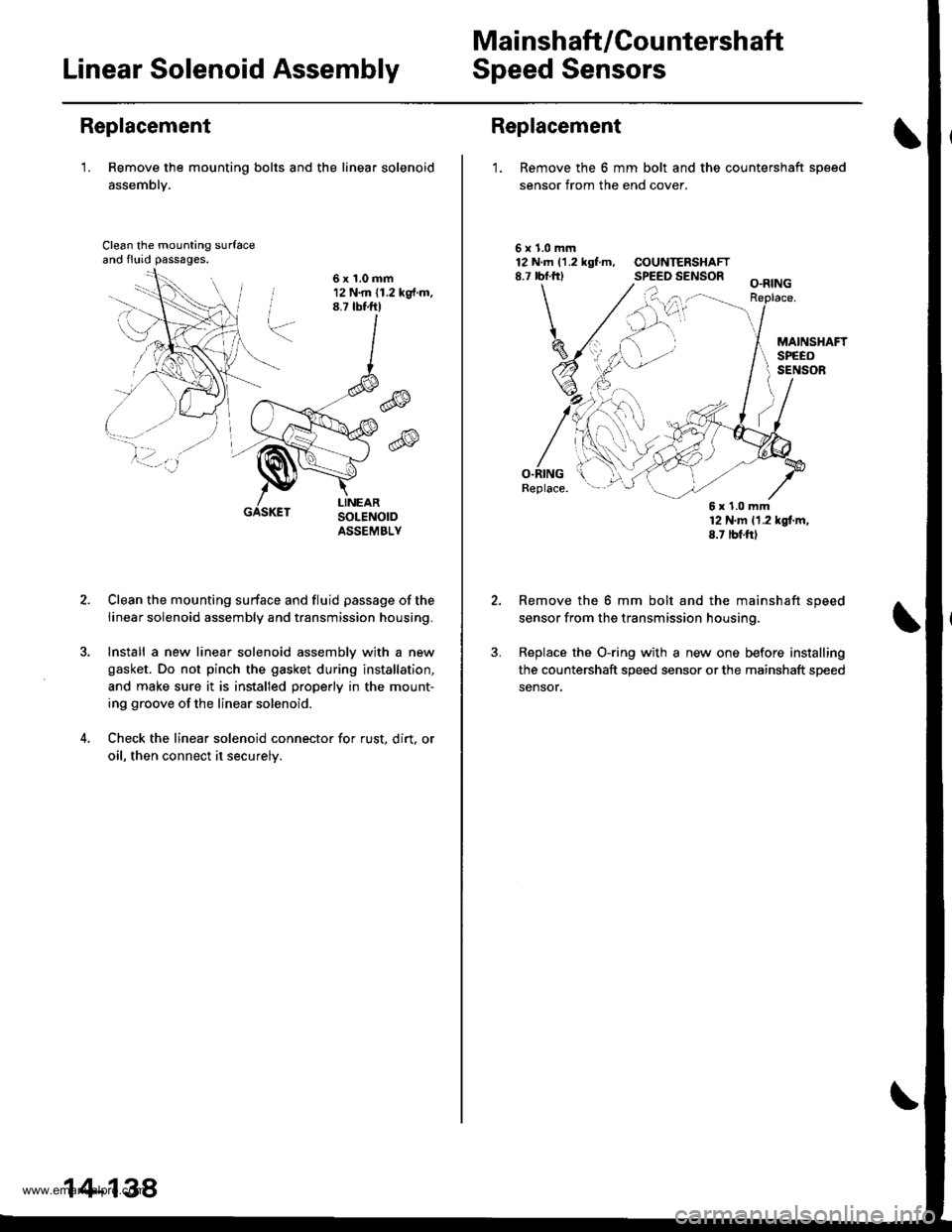
Mai nshaft /Cou ntershaft
Linear Solenoid AssemblySpeed Sensors
Replacement
'1. Remove the mounting bolts and the linear solenoid
assemblY.
Clean the mounting surfaceand fluid passages.
6x1.0mm12 N.m (1.2 kg{.m.8.7 tbtftl
@
@
GASKET
Clean the mounting surface and fluid passage of the
linear solenoid assembly and transmission housing.
Install a new linear solenoid assemblv with a new
gasket. Do not pinch the gasket during installation,
and make sure it is installed properly in the mount-
ing groove of the linear solenoid.
Check the linear solenoid connector for rust. dirt, or
oil, then connect it securelv.
14-138
Replacement
1. Remove the 6 mm bolt and the countershaft sDeed
sensor from the end cover.
\
5x1.0mm12 N.m 11.2 kgf.m, COUNTERSHAFT8.7 rbf.frl SPEED SENSOR
O.RINGReplace.
12 N'm 11.2 kgl.m,8.7 tbf.ftl
Remove the 6 mm bolt and the mainshaft speed
sensor from the transmission housing.
Replace the O-ring with a new one before installing
the countershaft speed sensor or the mainshaft speed
sensor,
6x1.0mm
www.emanualpro.com
Page 684 of 1395
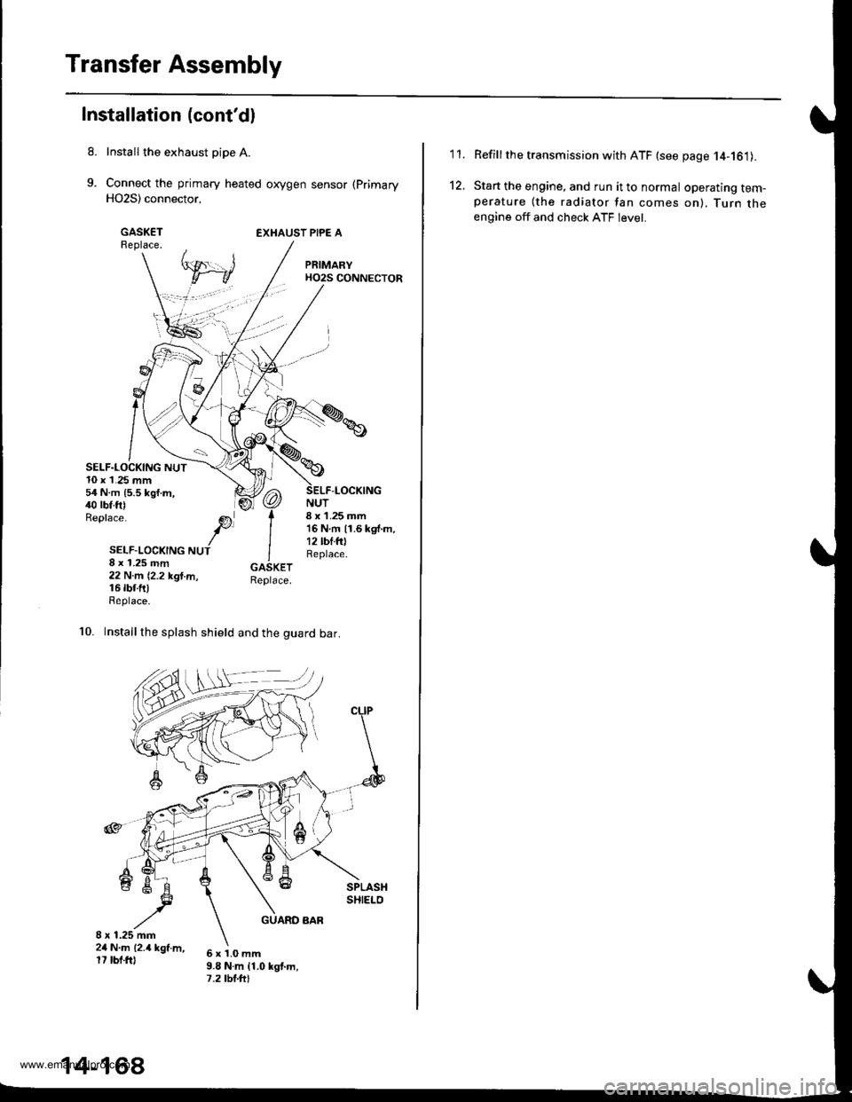
Transfer Assembly
Installation (cont'dl
Install the exhaust pipe A.
Connect the primary heated oxygen sensor (Primary
H02S) connector,
GASKETReplace.EXHAUST PIPE A
SELF.LOCKING NUT10 x 1.25 mm54 N.m {5.5 kgf.m,40 rbf.ft)Replace.
NUT8 x 1.25 mm16Nm11.6kgf.m,12 lbf.fOReplace.
-LOCKING
SELF-LOCKING NUT8 x 1.25 mm22 N.m (2.2 kgl.m,16 rbr.fttReplace.
10. Installthe splash shield and the guard bar.
6x1.0mm9.8 N.m {1.0 kgt.m,7.2 tbt.ftt
14-168
'I '�I.
12.
Refillthe transmission with ATF (see page 14-161).
Start the engine, and run it to normal operating tem-perature (the radiator fan comes on), Turn theengine off and check ATF level.
www.emanualpro.com
Page 687 of 1395
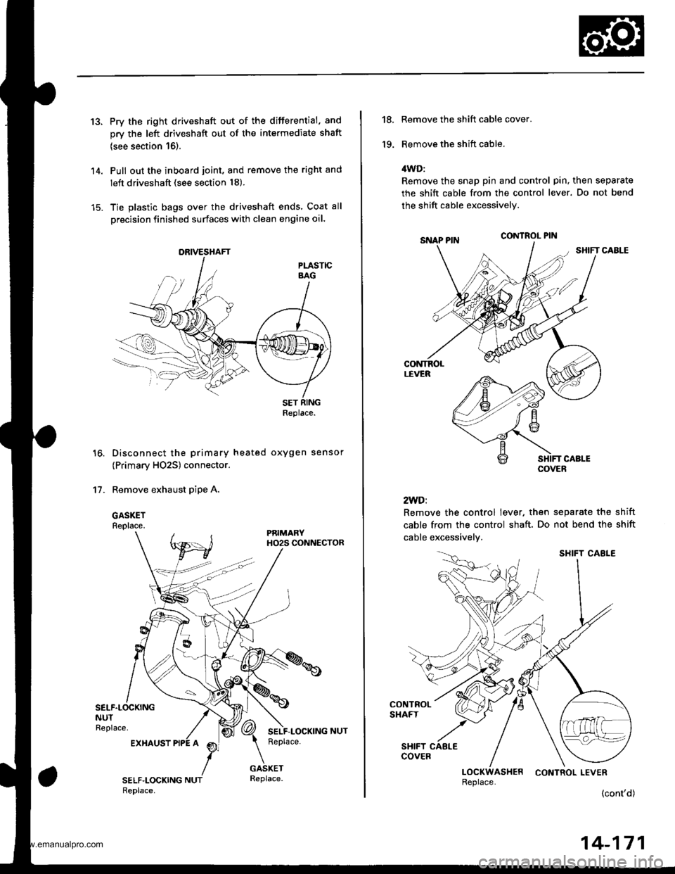
13.Pry the right driveshaft out of the differential. and
orv the left driveshaft out of the intermediate shaft
{see section 16).
Pull out the inboard joint, and remove the right and
left driveshaft (see section 18).
Tie plastic bags over the driveshaft ends. Coat all
Drecision finished surfaces with clean engine oil.
Disconnect the primary heated oxygen sensor
(Primary HO2S) connector.
Remove exhaust pipe A.
GASKETReplace.
14.
16.
't7 .
ORIVESHAFT
Replace.
EXHAUST
14-171
18.
19.
Remove the shift cable cover.
Remove the shift cable.
ilWD:
Remove the snap pin and control pin, then separate
the shift cable from the control lever. Do not bend
the shift cable excessively.
2WD:
Remove the control lever, then separate the shift
cable from the control shaft. Do not bend the shift
cable excessivelv.
Replace.
SHIFT CAELE
www.emanualpro.com
Page 691 of 1395
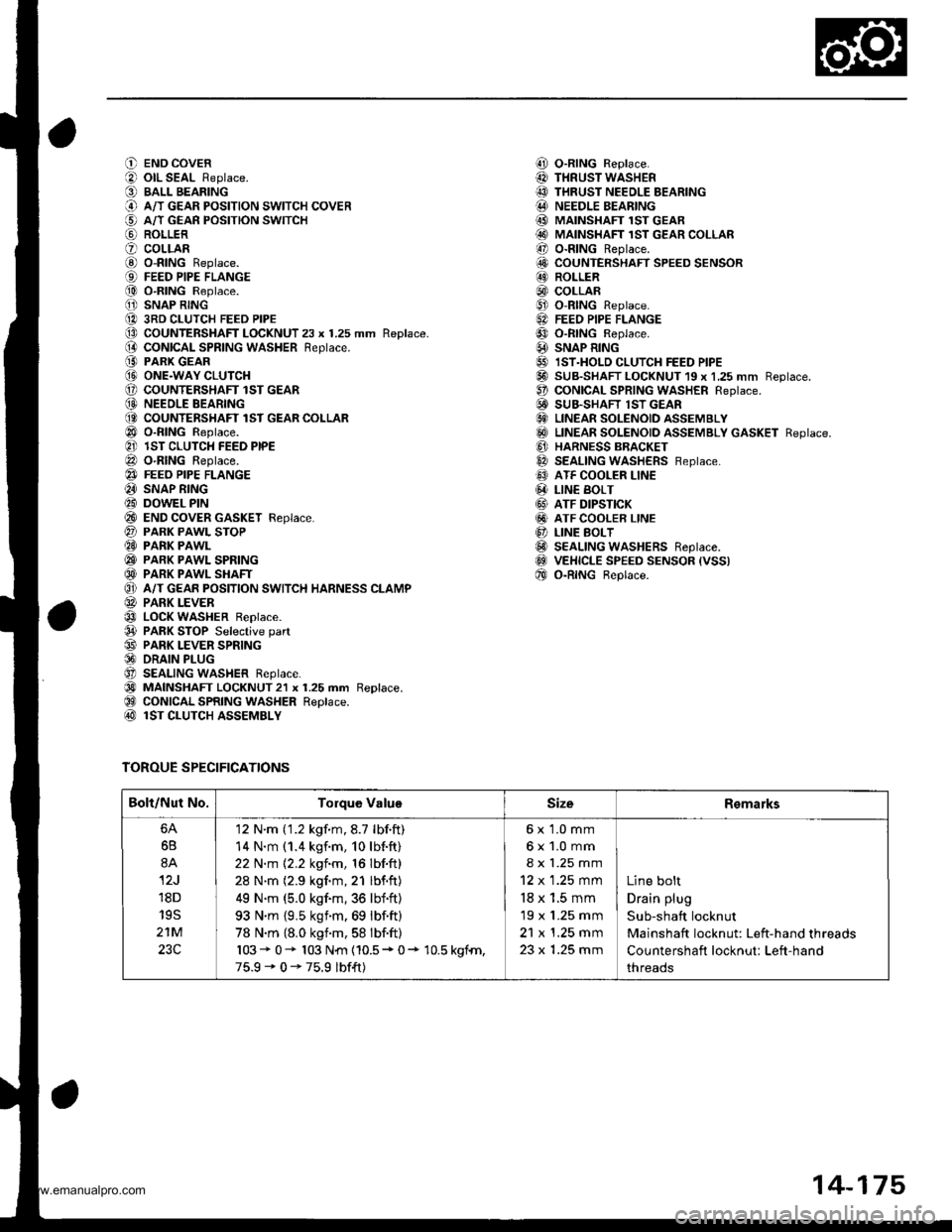
O END COVER
O olL SEAL Replace.
O BALL BEARING
@ A/T GEAR PoSITIoN swITcH coVER
€) A/T GEAn PosrloN swrrcH
@ ROLLER
O coLLARG) o-RING Replace.{9) FEED PIPE FLANGE
@ O-RING Replace.
O SNAP RING
@ 3RD CLUTCH FEED PIPE(D CoUNTERSHAFT LOCKNUT 23 x 1.25 mm Replace.(} coNtcAL SPR|NG WASHER Reptace.
@ PARK GEAR@ ONE.WAY CLUTCH(, COUNTENSHAFT lST GEAR(D NEEOLE BEARING(O COUNTERSHAFT lST GEAR COLLAR
@ o-RING Reptace.
@ lST CLUTCH FEED PIPE
@ O-RING Reptace.
@} FEEO PIPE FLANGE
@ SNAP RING
@ DOWEL PIN
@ END coVER GASKET Feplace.
@ PARK PAWL SToP@ PARK PAWL
@ PARK PAWL SPRING
@ PARK PAWL SHAFT
O} A/T GEAR POSITION SWITCH HARNESS CLAMP
@ PARK LEVER
@ LOCK WASHER Replace.
@ PARK STOP Selective part
@ PARK LEVER SPRING@ DRAIN PLUG
O SEALING WASHER Reptace.
@) MAINSHAFT LOCKNUT2l x 1.25 mm Replace.@ CONICAL SPRING WASHER Replace.@ lST CLUTCH ASSEMBLY
TOROUE SPECIFICATIONS
i!, O-RING Replace.
@ THRUST WASHER
@ THRUST NEEDLE BEARING@ NEEDLE BEARING
@ MAINSHAFI 1ST GEAR@ MAINSHAFT 1sT GEAR coLLAR
@ o-RING Replace.
6!, COUNTERSHAFT SPEED SENSOR@ ROLLER
@) COLLAR@ o-RtNG Replace.
6A FEEo PIPE FLANGE
@ o-RtNG Reptace.
@ SNAP R|NG
@ IST.HOLD cLUTcH FEED PIPE@ SUB-SHAFT LOCKNUT 19 x 1,25 mm Reptace.O coNtCAL SPR|NG WASHER Reptace.E! SUB.SHAFT lST GEAR€} LINEAR SOLENOID ASSEMBLY
@ LTNEAR soLENotD aSSEMBLy GASKET Reptace.
@ HARNESS BBACKET
@ SEALING WASHERS Feptace.
@ ATF COOLER LINE
@ LIN€ BoLT
@ ATF DIPSTICK
@ ATF COOLER LINE
@ LINE BoLT@ SEALING WASHERS Reptace.@ VEHICLE SPEED sENsoR (vss)
@ o-RtNG Beptace.
Bolt/Nut No.Torque ValuoSizeRemarks
6B
8A
12J
18D
19S
21M
23C
'12 N'm ('1.2 kgf.m,8.7 lbf.ft)
14 N.m (1.4 kgf.m, 10lb{.ft}
22 N.m 12.2 kgf.m, 16 lbf.ft)
28 N'm (2.9 kgf.m,21 lbf.ft)
49 N.m (5.0 kgf.m,36 lbf'ft)
93 N'm {9,5 ksim.69 lbf.ft)
78 N.m {8.0 kgnm,58 lbf.ft)
103* 0- 103 N{n {10.5* 0+ 10.5 kgfn,
75.9-0-75.9 lbf{t)
6x 1.0 mm
6x1.0mm
8 x 1.25 mm
12 x 1.25 mm
18 x 1.5 mm
19 x 1.25 mm
21 x 1.25 mm
23 x 1.25 mm
Line bolt
Drain plug
Sub-shaft locknut
Mainshaft locknut: Left-hand threads
Countershaft locknut: Left-hand
threads
14-175
www.emanualpro.com