Gasket HONDA CR-V 2000 RD1-RD3 / 1.G Repair Manual
[x] Cancel search | Manufacturer: HONDA, Model Year: 2000, Model line: CR-V, Model: HONDA CR-V 2000 RD1-RD3 / 1.GPages: 1395, PDF Size: 35.62 MB
Page 772 of 1395
Transmission
Reassembly lcont'd)
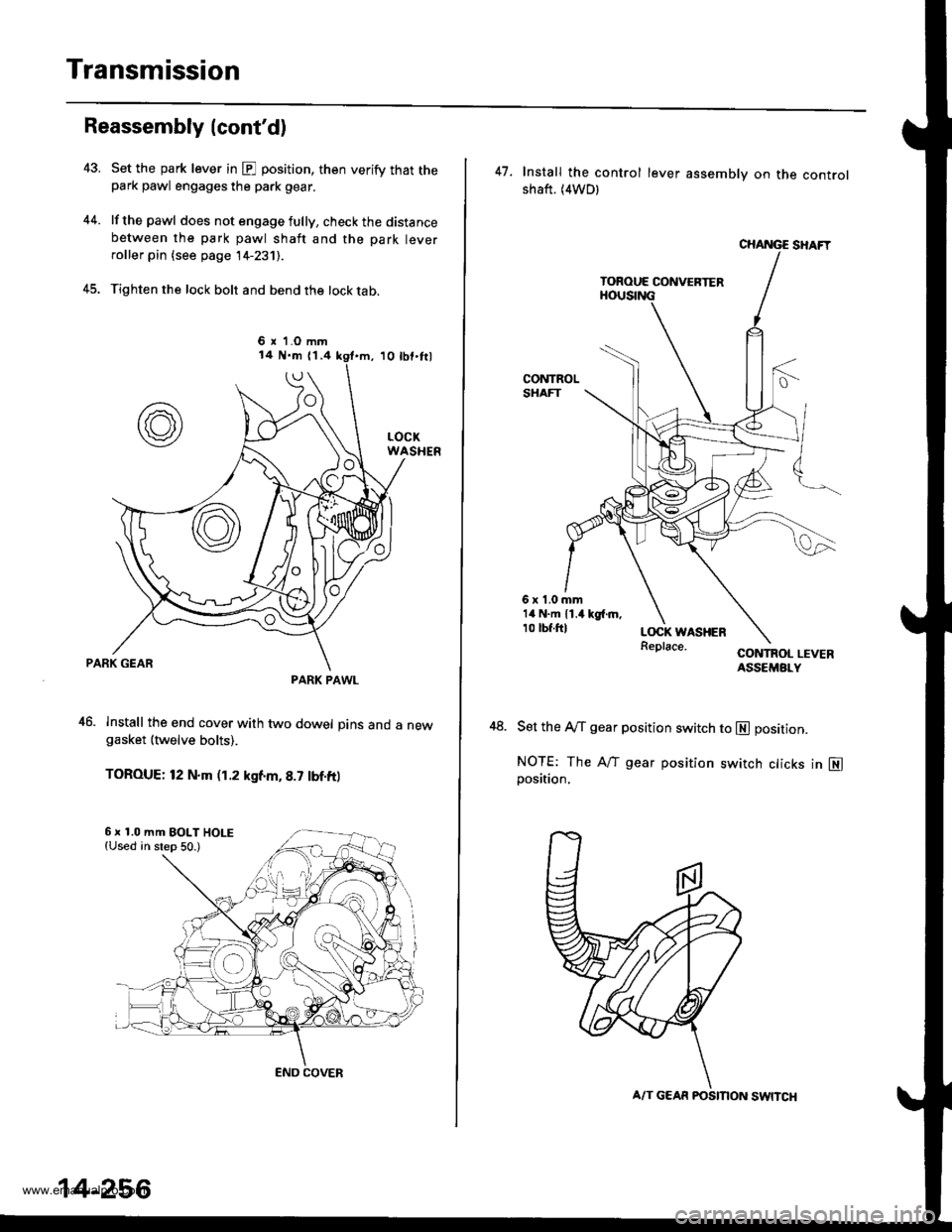
44.
Set the park lever in @ position, then verify that thepark pawl engages the park gear.
lf the pawl does not engage fully, check the distancebetween the park pawl shaft and the park leverroller pin (see page 14-231).
Tighten the lock bolt and bend the lock tab.
1o tbf'frl
PARK GEAR
46. Install the end cover with two dowel pins and a newgasket {twelve bolts).
TOROUE: 12 N.m (1.2 kgf.m, 8.7 tbf.ft)
6 r 1.O mm
PARK PAWL
6 x 1.0 mm EOLT HOLE{Used in step 50.)
END COVER
14-256
A/T GEAR FOSMON SWNCH
47. Install the control lever assemblv on the controlshaft. (4WDl
6x1.0mm14 N.m 11.4 kg{.m,10 tbf.ftl
48.
CONTROL LEVERASSEMBLY
Set the A/f gear position switch to E] position.
NOTE: The Aff gear position switch cticks in N]position,
www.emanualpro.com
Page 778 of 1395
Transmission
Installation (cont'dl
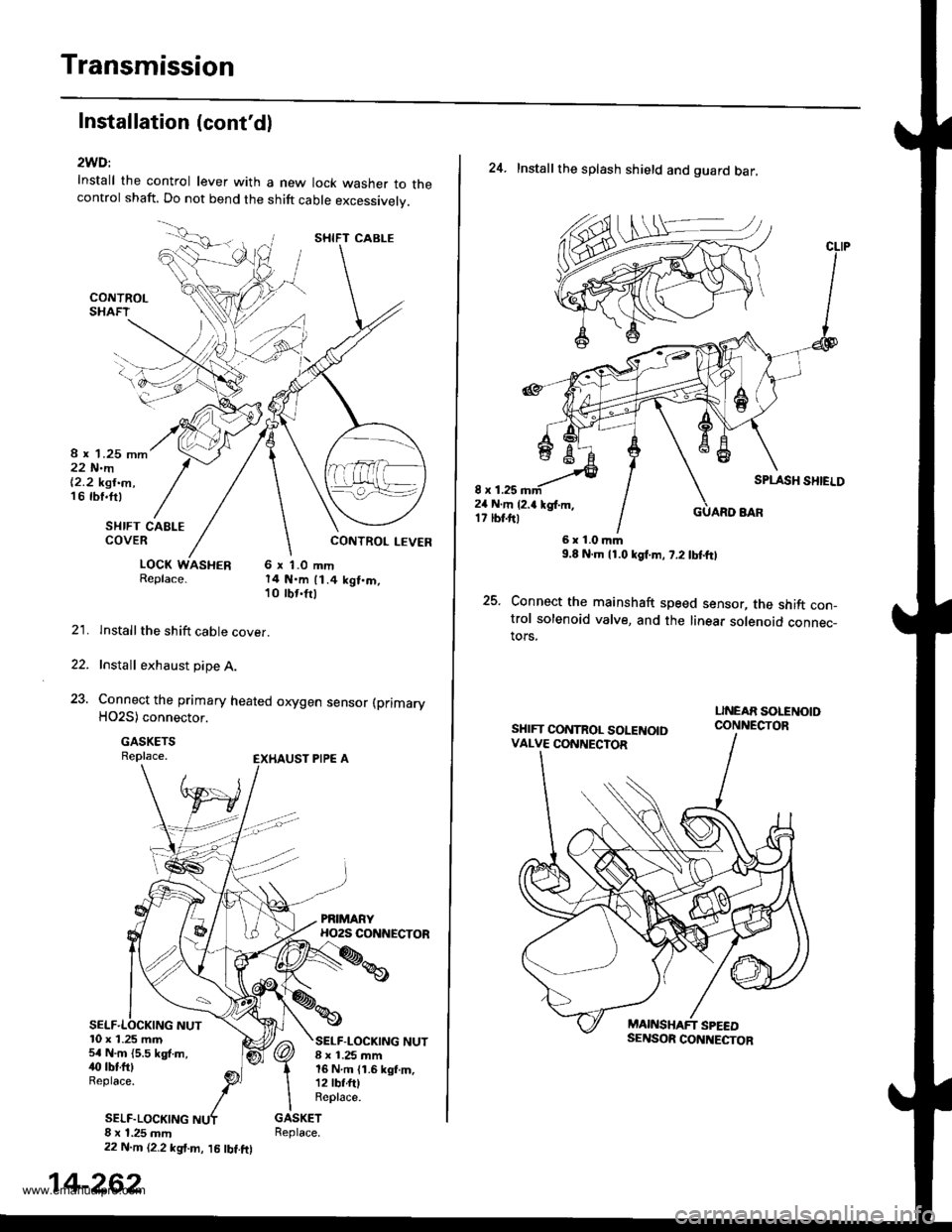
2WD:
Install the control lever with a new lock washer to thecontrol shaft. Do not bend the shift cable excessivelv.
8 r 1.25 mm22 N.m|'2.2 kgt.m,16 rbf.ft)
SI{IFT CAELECOVER
LOCK WASHER 6 x 1.0 mmReplace. 14 N.m 11.4 kgt.m,10 tbr.frl
lnstallthe shift cable cover.
Install exhaust pipe A.
Connect the primary heated orygen sensor (primary
HO2S) connector.
GASKETSReplace.
22.
23.
10 x 1.25 m.n5r N.m {5.5 kgf.m,40 tbtftlReplace.
SELF.LOCKING
SELF-LOCKING NUT8 ! 1.25 mm16 N.m {1.6 kgf.m,12 lbf.fttReplace.
8 x 1.25 mm22 N.m {2,2 kgt.m, l5 lbt.ftl
SHIFT CABLE
14-262
24. Installthe splash shield and guard bar,
8 x 1.2524 N.m {2.a kgl.m,17 tbt.ftl
SPLASH SHIELD
GUARO BAR
25.
6r1.0|r|m9.8 N.m l1.0lgf.m, 7.2 tbtftl
Connect the mainshaft speed sensor, the shift con-trol solenoid valve, and the linear solenoid connec_tors,
SHIFT CONTROL SOLENOIDVALVE CONNECTOR
www.emanualpro.com
Page 808 of 1395
Differential Carrier Assembly
Leak Repair
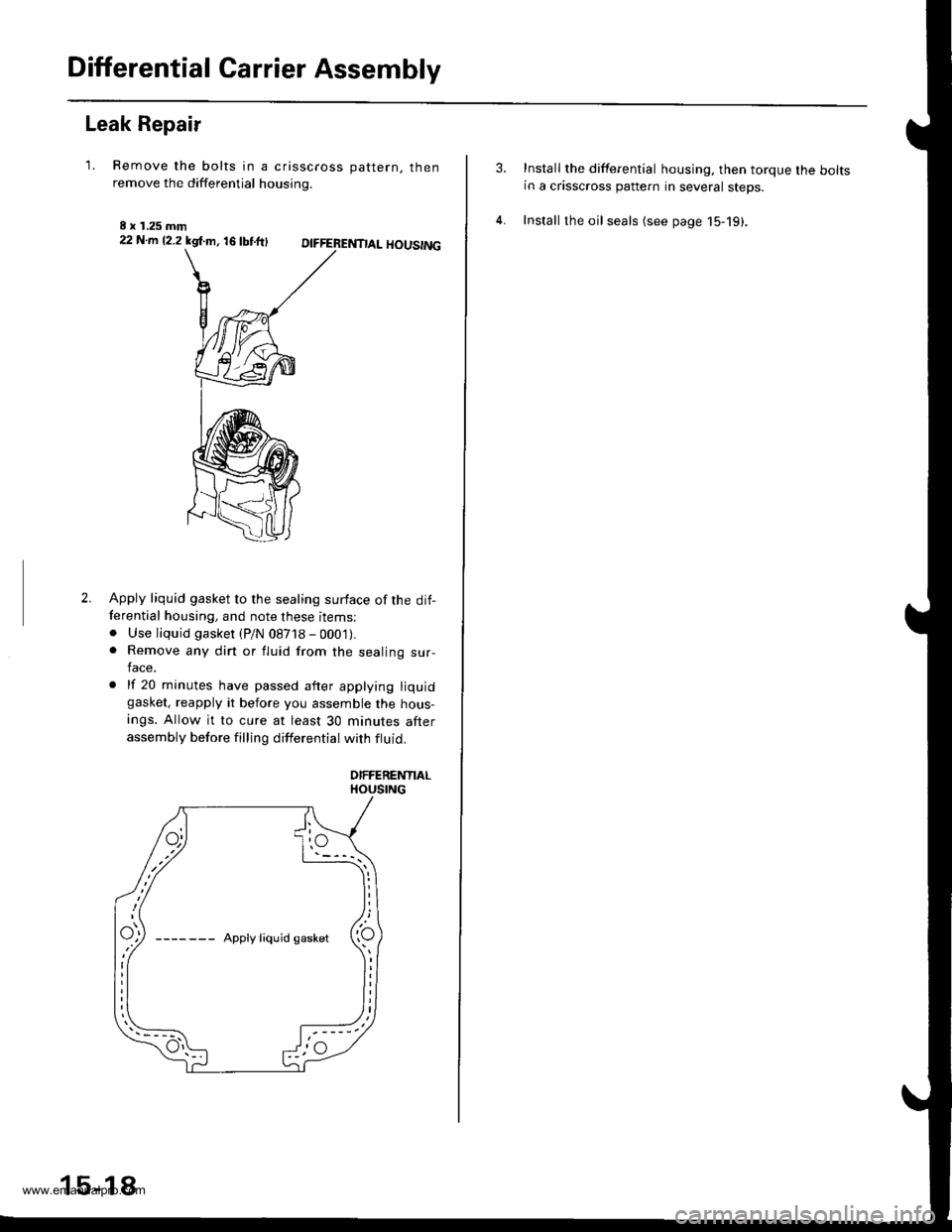
'1. Remove the bolts in a crisscross oattern. thenremove the differential housing.
I x 1.25 mm22 N.m 12.2 kgl.m, 16 tbtftlDIFFERENTIAL HOUSING
2.Apply liquid gasket to the sealing surface of the dit-ferential housing, and note these items:. Use liquid gasket (P/N 08718 - 000'1).. Remove any dirt or fluid from the sealing sur-lace.
. lf 20 minutes have passed after applying liquidgasket, reapply it before you assemble the hous-
ings. Allow it to cure at least 30 minutes afterassembly before filling differential with ftuid.
DIFFERENTIALHOUSING
15-18
Install the differential housing. then torque the boltsin a crisscross pattern in several steps.
Install the oil seals (see page 15-19).
www.emanualpro.com
Page 814 of 1395
Rear Differential Assembly
Reassembly (cont'dl
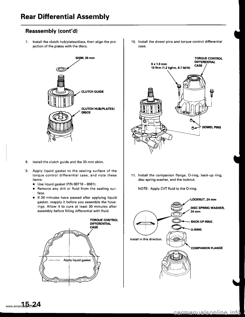
7. Install the clutch hub/plates/discs, then align the pro-
jection of the plates with the discs.
M, 30 mm
CLUTCH GUIDE
sHl
,/
.A-\,/r\-7
8.
9.
CLUTCH HUA/PLATES/Dtscs
Installthe clutch guide and the 30 mm shim.
Apply liquid gasket to the sealing surface of the
torque control differential case, and note these
rlems:
. Use liquid gasket (P/N 08718 - 0001).
. Remove any dirt or fluid from the sealing sur-
face.
. lf 20 minutes have passed after applying liquid
gasket, reapply it before you assemble the hous-
ings. Allow it to cure at least 30 minutes after
assembly before filling differential with fluid.
TOBOUE CONTROLDIFFERENNAL
--- Apply liquid gaskot
15-24
6x1.0mm12 N.m 11.2 tgf m,8.7lbt.ftl
10. lnstall the dowel pins and toroue control differential
case.
TOROUE CONTNOL
11. Install the companion flange, O-ring, back-up ring,
disc spring washer, and the locknut.
NOTE: Apply CW fluid to the O-ring.
,24mm
DISC SPRING WASHER,2a mm
lnstall in this direction.
@+-_alcr-upnwc
COMPANION FLAI{GE
/r-
K@#/
www.emanualpro.com
Page 1148 of 1395
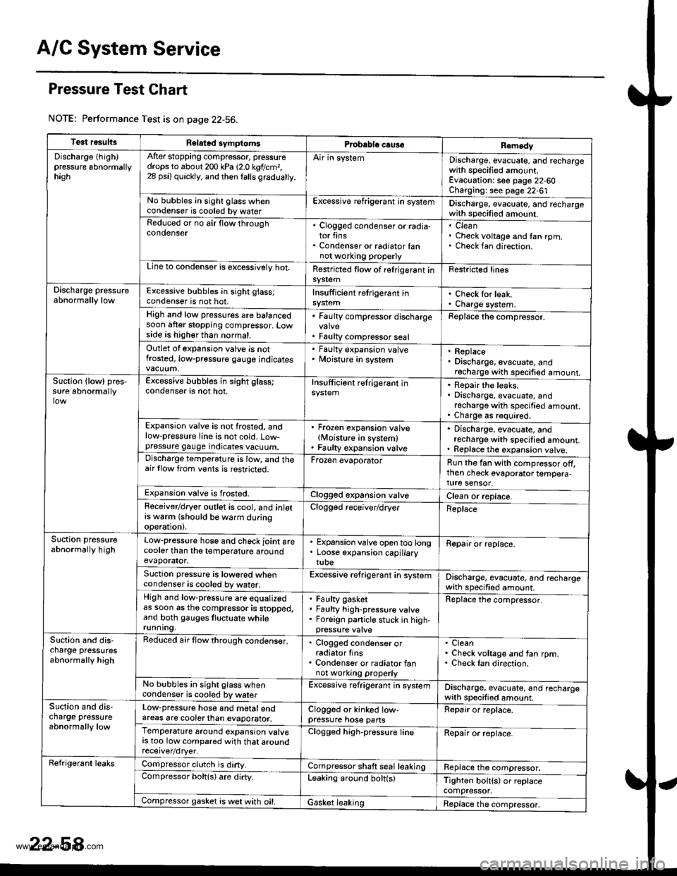
A/C System Service
Pressure Test Chart
NOTE: Performance Test is on page 22-56.
Test resultsRelatad symptomsPrcbable caus€Remody
Discharge (high)pressure 6bnormallyhagh
After stopping compressor, pressuredrops to about 200 kPa 12.0 kgtlcm,,28 psi) quickly, and then lalls gradualty.
Air in systemDischarge, evacuate, and rechargewith specified amount.Evacuation: see page 22-60Charging: see page 22-61No bubbles in sight glass whencondenser is cooled by waterExcessive refrigerant in systemDischarge, evacuate, and rechargewith specilied amount.Reduced or no air flow throughcondenser. Clogged condenser or radia-tor fins. Condenser or radiator fannot wo.king properly
CleanCheck voltage and fan rpm.Check fan direction.
Line to condensor is excossivelv hot.Restricted flow of relrigerant insy$emFestricted lines
Discharge pressureabnormally lowExcessive bubbles in sight glass;condenser is not hot.Insufficient retrigerant inCheck for leak.Charge system.High and low pressures are balancedsoon after stopping compressor. Lowside is higher than normal.
. Faulty compressor discharge
. Faulty compressor seal
Replace the comprossor.
Outlet ot expansion valve is notfrosted, low-pressure gauge indicates
' Faulty expansion valve. Moisture in system. Replace. Discharge, evacuate, andrecharge with specified amount.Suction {low) pros,sure abnormallyExcessive bubbles in sight glass;condenser is not hot.Insufficiont relrigerant inRepair the leaks.Discharge, evacuate, andrecharge with specified amount.Charge as r€quired.Expansion valve is not frosted, andlow-pressure line is not cold. Low-pressure gauge indicates vacuum.
' Frozen expansion valvelMoisture in system). Faulty expansion valve
. Discharge, evacuate, andrecharge with specitied amount.. Replace th€ expansion valve.Discharge temperature is low, and theair llow trom vents is restricted.Frozen evaporatorRun the fan with compressor off,then check evaporator tempera,ture sensor.Expansion valve is frosted.Clogged expansion valveClean or replace.Feceiver/dryer outlet is cool, and inlotrs w6rm (should be warm duringoperation).
Clogged receiver/dryerReplace
Suction pressureabnormally highLow-pressure hose and check joint arecooler than tho temperature aroundevaporator.
. Expansion valve open too long. Loose expansion capillarytube
Repair or roplace.
Suction pressure is lowored whencondenser is cooled by water.Excessive refrigerant in systemDischarge, evacuate, and rechargewath specified amount.High and low-pressure are equalizedas soon as tho compressor is stopped,and both gauges tluctuate whilerunning.
Faulty gasketFaulty high-pressure valveForeign panicle stuck in high-
Replace the compressor.
Slction and dis,charge pressutesabnormally high
Reduced air flow through condens€r,. Clogged condenser orradiator tins. Condenser or radiator fannot working properly
CleanCheck voltage and fan rpm.Check Ian direction.
No bubbles in sight glass whencondenser is cooled by walerExcessive refrigerant jn systemDischarge, evacuate, and rechargewith specified amount.Suction and dis-charge pressureabnormally low
Low-pressure hose and motalendareas are cooterlhan evaporator.Clogged or kinked low-pressure hose pansRepair or replace.
Temperature around expansion valvers too low compared with that aroundClogged high-pressure lineRepair or replace.
Refrigerant leaksCompressor clutch is diny.Compressor shaft seal leakingReplace the compressor.Compressor boltls) are dirty.Leaking around bolt(s)Tighton bolt{s) or replacecompressor.Compressor gasket is wet with oil.Gasket leakingReplace the compressor,
www.emanualpro.com
Page 1242 of 1395
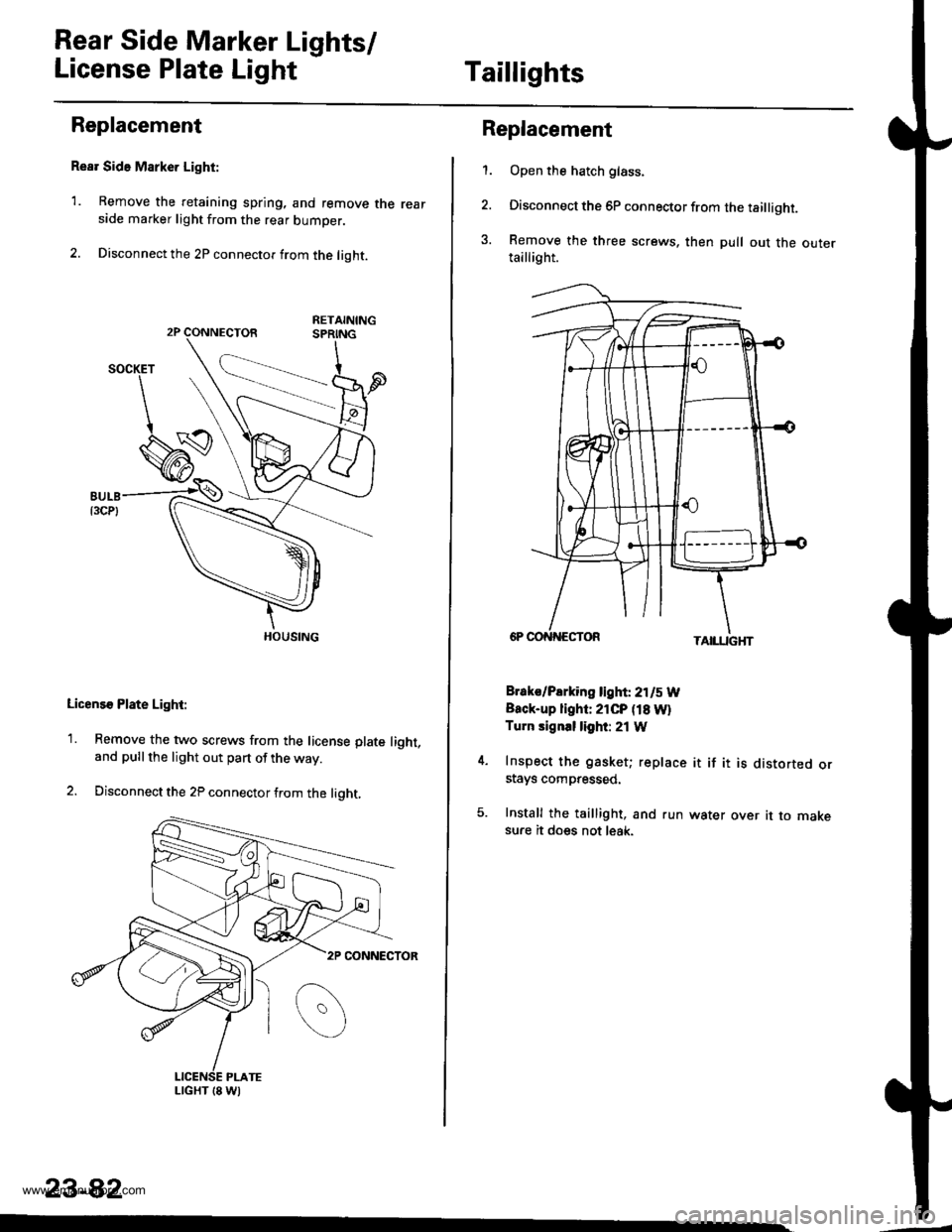
Rear Side Marker Lights/
License Plate LightTaillights
Replacement
Rear Side Marke. Light:
1. Remove the retaining spring, and remove the rearside marker light from the rear bumper.
2. Disconnect the 2P connector from the light.
RETAINING
HOUSING
Licens€ Plate Light:
1. Remove the two screws from the license plate light,and pull the light out part of the way.
2. Disconnect the 2P connector from the light,
23-A2
LIGHT (8 WI
Replacement
1. Open the hatch glass.
2. Disconnect the 6P connector from the taillight.
3. Remove the three screws, then pull out the outertaillight.
Brak€/Plrking light 2115 W
Back-up light: 21CP (18 W)
Turn signll light 21 W
Inspect the gasket; replace it if it is distorted or$ays compressed.
Install the taillight, and run water over it to makesure it does not leak.
www.emanualpro.com