Switch fan HONDA CR-V 2000 RD1-RD3 / 1.G Owner's Guide
[x] Cancel search | Manufacturer: HONDA, Model Year: 2000, Model line: CR-V, Model: HONDA CR-V 2000 RD1-RD3 / 1.GPages: 1395, PDF Size: 35.62 MB
Page 675 of 1395
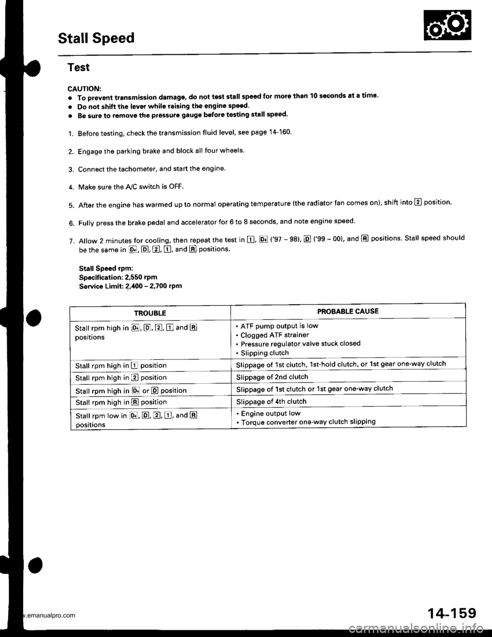
Stall Speed
Test
CAUTION:
. To prevent transmission damage, do not te3t stall speed for mors than 10 s€€onds at a time'
. Do not shift the lever while raising th€ engine spsed.
. Be sure to remove tho pressuro gauge bofore testing stall speed,
1. Before testing, check the transmission fluid level, s€e page 14-160.
2. Engage the parking brake and block all four wheels
3. Connect the tachometer, and start the engane.
4. Make sure the Ay'C switch is OFF
5. After the engine haswarmed upto normal operating temperature (the radiator fan comes on),shiftinto@ position.
6. Fully press the brake pedal and accelerator for 6 to 8 seconds, and note engine speed '
j. A|ow 2 minutes for cooling, then repeat the test in E, E ('97 - 98). E {'99 - 00}, and E positions. Stall speed should
be the same in E, E, E, tr. and E positions
Stall Speed rpm:
Specitication: 2,550 rpm
S€rvice Limit: ?,400 - 2.700 rpm
TROUBLEPROBAELE CAUSE
Stall rpm high in El, E, E, E and E
positions
ATF pump output is low
Clogged ATF strainer
Pressure regulator valve stuck closed
Slipping clutch
Stall rpm high in E positionSlippage of 1st clutch, 1st-hold clutch, or 1st gear one-way clutch
Stall rpm high in E positionSlippage of 2nd clutch
stall rpm high in E! or E positionSlippage of 1st clutch or 1st gear one-way clutch
Stall rpm high in E positionSlippage of 4th clutch
Stall rpm low in [dd, E. E, E, ana E
positions
. Engine output low
. Torque converter one-way clutch slipping
14-159
www.emanualpro.com
Page 779 of 1395

26. Connect the vehicle speed sensor (VSS). the coun-
tershaft speed sensor. and the A,/T gear position
switch connectors,
VEHICLE SPEEO
SPEED SENSOACO'{NECTOR
Connect the lock-up control solenoid valve connec-
tor, then install the harness clamp on the clamp
bracket.
HARNESS CI-AMP
27.
RADIATOR HOSECLAMP
TRANSMISSIONGROUND CAB1ITERMINAL
LOCK-UP OONTROLSOLENOID VALVECONNECTOR
6x1.0mm12 N'm (1.2 kgi.m,8.? tbtftl
28.
29.
Instail the transmission ground cable terminal on
the transmission hanger, and install the radiator
hose clamp on the transmission hanger,
Connect the starter cables to the starter, and install
the harness clamD on the clamD bracket. Make sure
the crimped side of the starter cable ring terminal is
facing out.
STARTEBCABLE
STARTER CAAtf,
Install the air cleaner housing assembly and the
intake air duct.
Refill the transmission with ATF (see page 14-161).
Connect the battery positive terminal and negative
terminal.
Set the parking brake, Start the engine, and shift the
transmission through all gears three times.
Check the shift cable adjustment (see page 14-271]-.
Check the tront wheel alignment and adjust it if
needed (see section 18).
Let the engine reach normal operating temperature
(the radiator fan comes on) with the transmission in
E or N position, then turn it off and check the ATF
level {see page 14-160).
Perform a road test (see page 14-157 and 14-158).
30.
31.
34.
CLAMP BRACKET
37.
14-263
www.emanualpro.com
Page 1095 of 1395
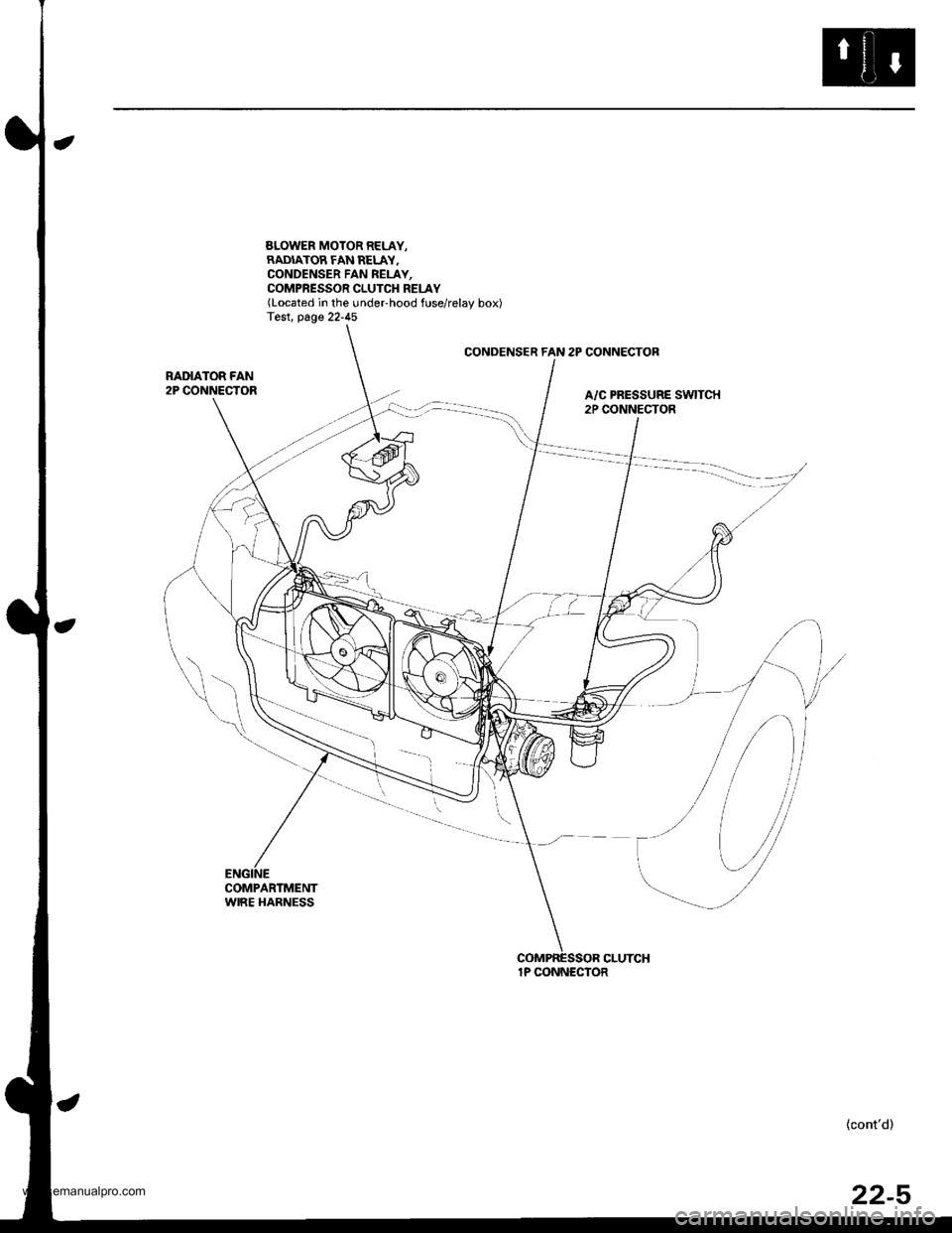
SLOWER MOTOR RELAY,RADIATOR FAN RELAY.CONDENSER FAN REI-AY,COMPRESSOR CLUTCH RELAY(Located in the undeFhood fuse/relay box)Test. page 22-45
CONDENSER FAN 2P CONNECTOB
RADIATOR FAN2P CONNECTORA/C PRESSURE SWITCH2P CONNECTOR
COMPARTMENTWIRE HARNESS
{cont'd)
1P CONNECTOR
22-5
www.emanualpro.com
Page 1118 of 1395
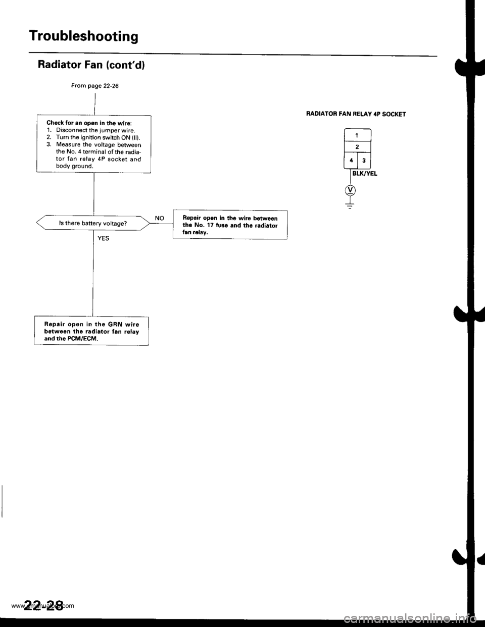
Troubleshooting
Radiator Fan (cont'dl
From page 22-26
RADIATOR FAN RELAY 4P SOCKET
BLK/YEL
1
2
a
Chock for an open in the wire:'1. Disconnect the jurnper wire.2. Turn the ignition switch ON (ll).3. lleasure the voltage betweenthe No.4terrninal of the radia-tor fan relay 4P socket andbody ground.
R€pair open in th6 wire botwoonthe No. 17 fuso and the radiatolfan .elsy.
ls there battery voltage?
Rep.ir open in the GRN wirebotw€en lhe radiator tan relayand the PCM/ECM.
22-28
www.emanualpro.com
Page 1121 of 1395
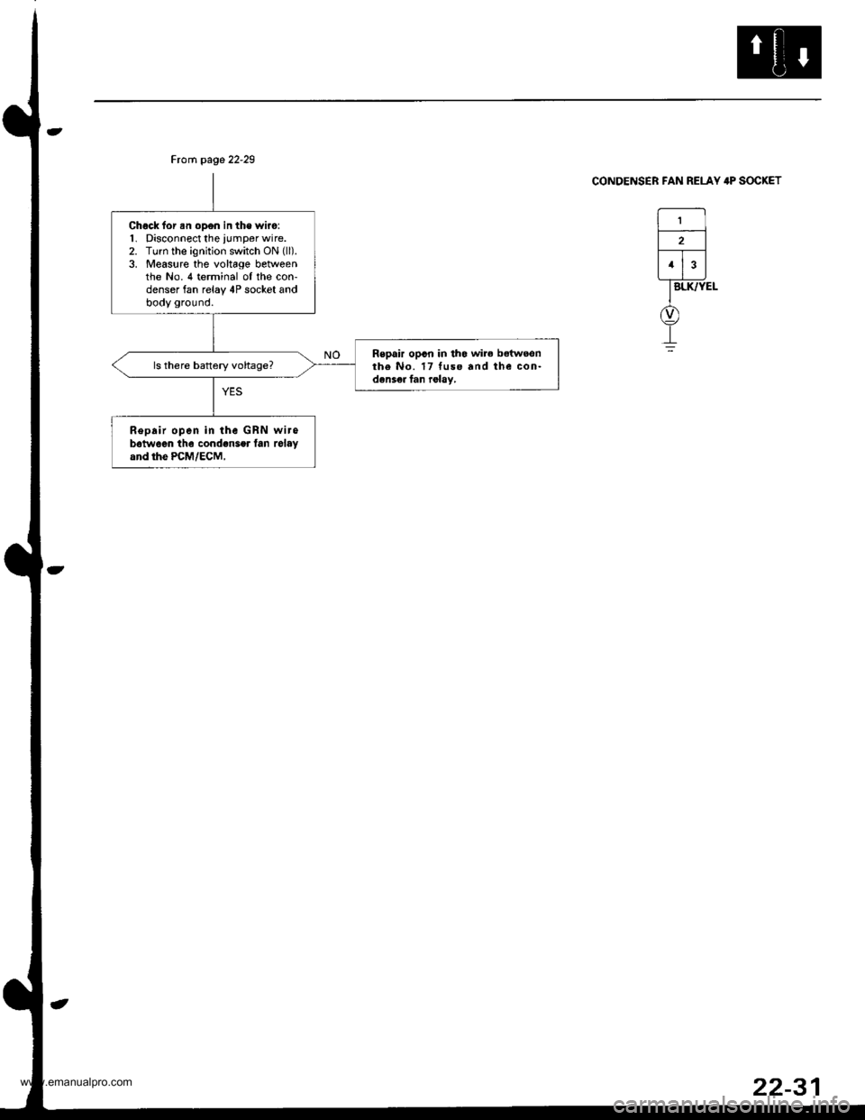
Chock for an open in the wiro:1. Disconnect the iumper wire.2. Turn the ignition switch ON (ll).
3. Measure the voltage betweenthe No. 4 terminal oI the con-denser fan relay 4P socket andbody ground.
Repair opcn in tho wire betwoonthe No. 17 tuse and the con-densea fan relay,
Repair open in the GRN wirob6tw6en the cond.nser lan relayand rhe PcM/EcM,
Ftorn page 22-29
CONDENSER FAN RELAY 4P SOCKET
22-31
www.emanualpro.com
Page 1122 of 1395
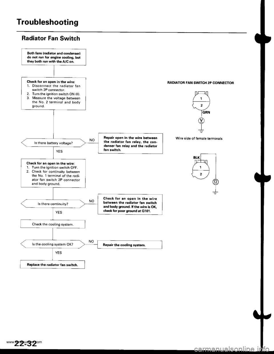
Radiator Fan Switch
RADIATOB FAN SWITCH 2P CONNECTOR
1
'.r
GRN
Wire side of female terminals
Both tans (radiator and condenser)do not run fo. engine cooling, butthey both run with the A/C on.
Check lor rn open in the wire:1. Disconnect the radiator fanswitch 2P connector.2. Turn the ignition switch ON lll).3, Measure the voltage betlveenthe No.2 terminal and bodygrou nd.
Repair open in the wire betweenthe radiator tan relay, the con-densei lan .elay and the radiaiortan swhch.
ls there battery voltage?
Chock for an open in the wire:1. Turn the ignition switch OFF.2. Check for continuity betweenthe No. 1 terminal of the radi-ator fan switch 2P connectorand body ground.
Check for an open in the wirebetween the .adialor fan switchand body glound. I ths wire is OF;choc* tor poor g.ound at G'101.
ls there continuity?
ls the cooling system OK?
Replsce the radialor fan switch.
www.emanualpro.com
Page 1123 of 1395
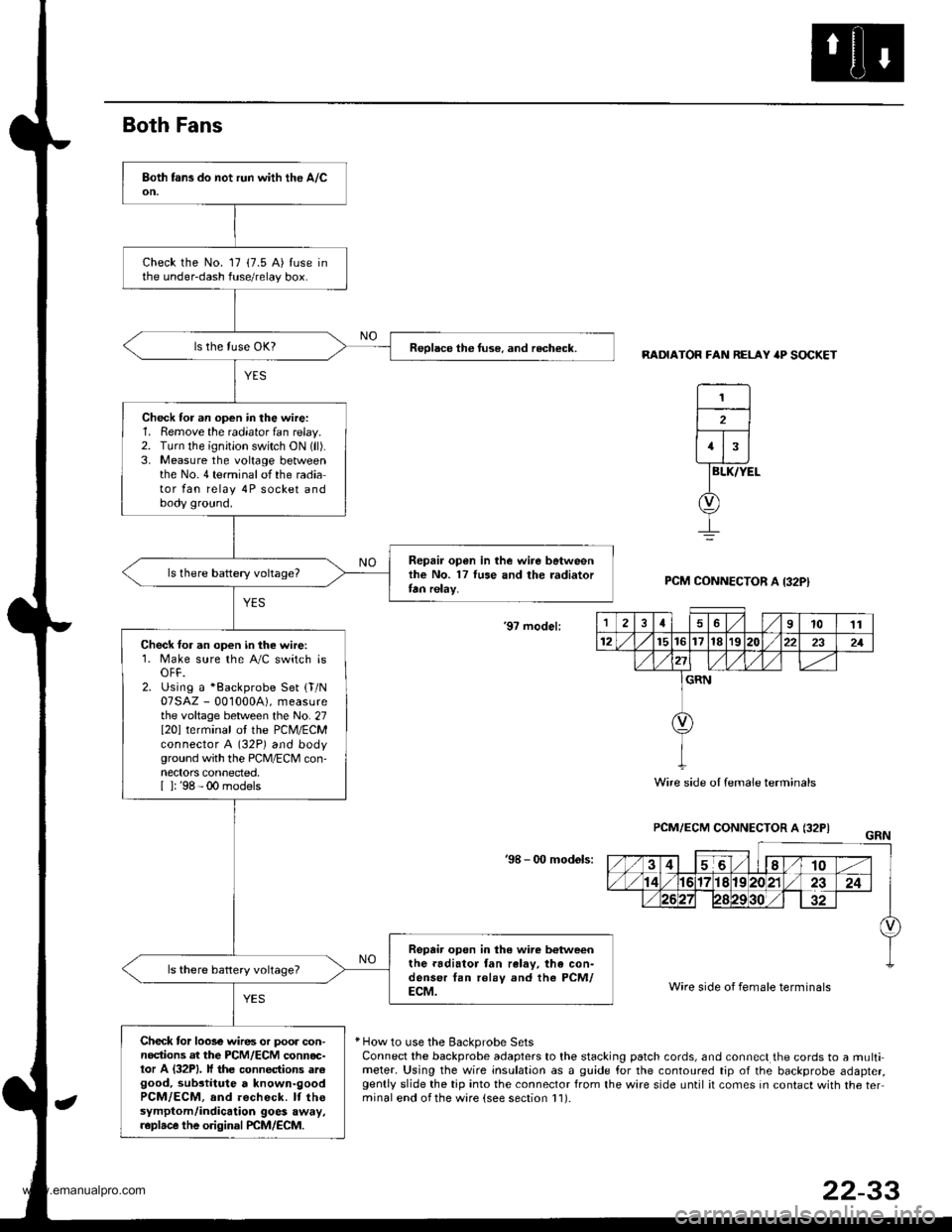
Both Fans
RADIATOR FAN RELAY 'P SOCKET
BLK/YEL
PCM CONNECTOR A I32PI
'9? model:
PCM/ECM CONNECTOR A (32PI
'98 - 0O mod6ls:
Wire side of female terminals
* How to use the Backprobe SetsConnect the backprobe adapters to the stacking patch cords, and connect the cords to a multimeter. Using the wire insulation as a guide for the contoured tip of the backprobe adapter,gently slide the tip into the connector from the wire side until it comes in contact with the terminal end ofthe ware {see section l1).
Check the No. 17 (7.5 A) tuse inthe under-dash fuse/relay box.
Reolace the tuse. and recheck.
Check for an op€n in the wire:1. Remove the radiator fan relay.2. TLrrn the ignition switch ON (ll).
3. Measure the voltage betweenthe No.4 terminalofthe radiator fan relay 4P socket andbody ground.
Repair open in the wire betweenlhe No. 17 luse and the radiatortan relay.
Check for an open in the wire:1. Make sure the A/C switch isOFF.2. Using a *Backprobe Set {T/N07SAZ - 001000A), measurethe voltage between the No. 27I20l terminal ol the PCM/ECMconnector A (32P) and bodyground with the PCM/ECM con-nectors connected.[ ]: '98 - 00 models
Repair open in the wire b€tweenthe.adiator fan ralav, the con-denser tan rolay and the PCM/ECM.
Check tor loose wires or poor con-nodions at the PCM/ECM connoc-tor A (32P1. lf the connections arcgood, substitute a known-goodPCM/ECM, and recheck. It thesymptom/indicalion goes away,r.plrce the original PCM/ECM.
1
2
1
12461011
12t5t61718r9222321
GRN
Wire side oI female terminals
22-33
www.emanualpro.com
Page 1127 of 1395
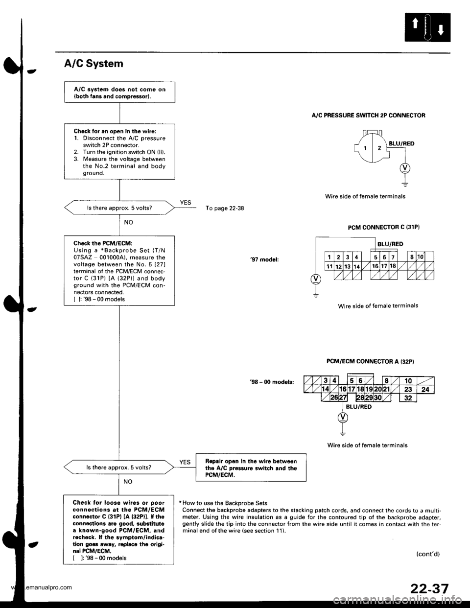
A/C aystem does not come on{both fans and comDrossor).
Ch6ck lor .n open in the wire:1. Disconnect the A,/C pressureswitch 2P connector.2. Turn the ignition switch ON (ll).
3. Measure the voltage betweenthe No.2 terminal and bodyground.
ls there approx. 5 volts?
check tho PcM/EcM:Using a *Backprobe Set (T/N
07SAZ 0010004). measure thevoltage between the No.5 t27lterminal of the PCM/ECM connec,tor C (31P) [A 132P)l and bodyground with the PCM/ECM con-nectors connected,I l: '98 - 00 models
Rop.ir open in th6 wire botweonthe A/C Dr*sure switch and thePCM/ECM.
ls there approx.5 volts?
Check tor loo3e wires or Doorconnections at the PCM/ECMconnoctor C l3lPl lA (32Pll. It theconnections arg good, 3ubdtitut€a known-good PCM/ECM, andrecheck. ll the 3ymptom/indica-tion go.. eway, r€placo thG origi-nal PCM/ECM,[ ]: '98 -00 models
A/C System
A/C PRESSURE SWITCH 2P CONNECTOR
fo page 22-38
PCM CONNECTOR C (31PI
'97 modol:
Wire side of female terminals
PCM/ECM CONNECTOR A I32P'
38 - 00 modeb:
Wire side of female terminals
* How to use the Backprobe SetsConnect the backprobe adapters to the stacking patch cords, and connect the cords to a multi-meter. Using the wire insulation as a guide for the contoured tip ol the backprobe adapter,gently slide the tip into the connector from the wire side until it comes in contact with the ter.minalond olthe wire (see section 11).
(cont'd)
22-37
www.emanualpro.com
Page 1146 of 1395
A/G System Service
Performance Test
The performance test will helD determine if the air con-
ditioner system is operating within specifications.
Use only service equipment that is U.L.-listed and is cer-
tified to meet the requirements of SAE J2210 to remove
HFC-134a (R-134a) from the air conditioner svstem.
CAUTION: Exposure to air condiiioner r€trigerant and
lubricant vapor or mist can irritate €yes, nose and
throat. Avoid bre8thing the air conditioner retrige.ant
and lubricant vapor or mist,
lf accidental system discharge occurs. ventilate work
area before resuming service.
R-134a service equipment o. vehicle air conditioner sys-
tems should not be pressure tested or leak tested with
comDressed air.
@ some mixtur€s ol air and R-134a have becn
shown to be combuslible at olsvated pressures and can
result in lire or explosion causing iniury or property
damage. Never use compressed air to prgssure test R-
13i[a service equipment or vehicle air conditioner sys.
tems.
Additional health and safety information may be obtained
from the refrigerant and lubricant manufacturers.
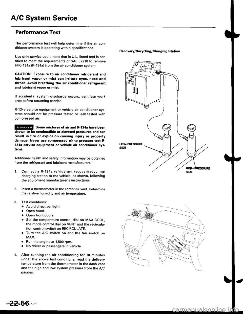
Recovory/Recycling/charging station
LOW.PRESSURESIDE
1.Connect a R-134a refrigerant recover/recycling/
charging station to the vehicle, as shown. following
the equipment manufacturer's instructions,
Insen a thermometer in the center air vent. Determine
the relative humidity and air temperature.
Test conditions:
. Avoid direct sunlight.
o Open hood.
. open front doors.
. Set the temperature control dial on MAX COOL,
the mode control dial on VENT and the reci.cula-
tion control switch on RECIRCULATE.
. Turn the A,/C switch on and the fan switch on
MAX.
. Run the engine at 1,500 rpm.
. No driver or passengers in vehicle
After running the air conditioning for 10 minutes
under the above test conditions, read the deliverv
temperature from the thermometer in the dash vent
and the high and low system pressure from the Ay'Cgauges.
2.
22-56
www.emanualpro.com
Page 1161 of 1395

Body Electrical
Speciaf Toofs ,...,..,.............-.23-2
Troubleshooting
Tips and Precautions ......,.,..........,.................. 23-3
Five-step Troubleshooting ........,.,.,...,,.,......... 23-5
Wire Color Codes ...,....,.. 23-5
Relay and Control Unit Locations
Engine Compartment ..,.,......,......................... 23-6
Dashboard ,.,.,..............-.- 23-7
Door ....................... .........23-10
Index to Cilcuits and Sysiems
Accessory Socket .. ,....,.,..,.,. 23-95*Airbags ................ .,....,. Sestion 24
Air Conditioning ,.,.,.... Section 22
Alternator ................... Section 4
Anti-lock Brake System {ABSI ................... Section 19'A/T Gear Position Indicator ....................... Section 1,1
Automatic Transmission System ...........,.. Section 14
Battery ................... ..............23-50
Blower Controls .,...,.,, Section 22
Charging System ....... Seqtion il
Clock -'98 Model ................ 23-98
Connector ldentification and Wire HarnessRouting .................. ......... 23.11
Cruise Control ............ Ssction 4
Dash Lights Brightness Contlo||er ..................... 23-90
Fan Conlrols ...,......,.... Section 10
Fuel Pump ,..,.,...,....,.... Section 11
Fuses...................... .,,.,.,.,.,,.,23-40*Gauges
Circuit Diagram ......-....-..23-58
Fuel Gauge .....,.,..... Section 11
Speedometer ..,..........,... 23-56
Ground Distribution ,....,.,...23-46
Hatch Glsss ODenor .........................,.,.,.,.,..,.,.,.,,. 23-121
Heater Controls .-........ Soction 21*Horns.,...,..,.,.,....... ................23"104*fgnition Switch ,,.,.,..,.,.,,.,.,.,23-51
lgnition Key Light System -'97 Mod6l .............. 23.88
-+
BODY
www.emanualpro.com