Transfer HONDA CR-V 2000 RD1-RD3 / 1.G Owner's Guide
[x] Cancel search | Manufacturer: HONDA, Model Year: 2000, Model line: CR-V, Model: HONDA CR-V 2000 RD1-RD3 / 1.GPages: 1395, PDF Size: 35.62 MB
Page 510 of 1395
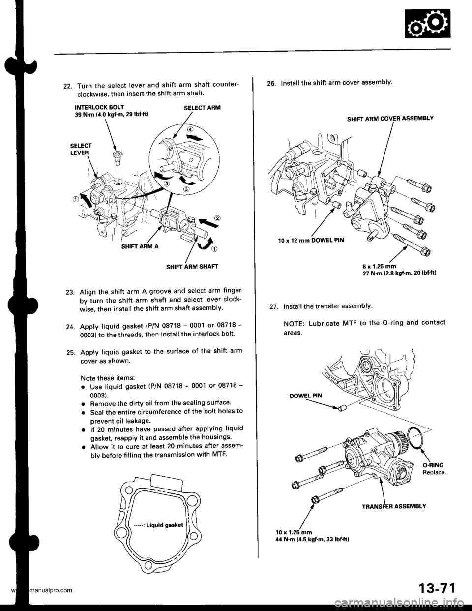
22. Turn the select lever and shift arm shaft counter-
clockwise, then insert the shift arm shaft.
INTERLOCK EOLT39 N.m (4.0 kqt ft, 29 lbf ft)SELECT ARM
SHIFT ARM A
Align the shift arm A groove and select arm finger
by turn the shift arm shaft and select lever clock-
wise. then installthe shift arm shaft assembly.
Apply liquid gasket (P/N 08718 - 0001 or 08718 -
OO03) to the threads, then install the interlock bolt'
Apply liquid gasket to the surface of the shift arm
cover as snown.
Note these items:
. Use liquid gasket (P/N 08718 - 0001 or 08718 -
0003).
. Remove the dirtv oilfrom the sealing surface.
. Seal the entire circumference of the bolt holes to
prevent oil leakage.
. lf 20 minutes have passed after applying liquid
gasket. reapply it and assemble the housings.
a Allow it to cure at least 20 minutes after assem-
bly betore filling the transmission with MTF.
23.
-->.-
(
SHIFT ARM SHAFT
SHIFT ARM COVER ASSEMBLY
10 x 12 mft DOWEL PIN
t1
26. Install the shift arm cover assembly.
I x 1.25 mm27 N m 12.8 kgt m,20 lbf'ft)
Install the transfer assemblY.
NOTE: Lubricate MTF to the O-ring and contact
areas.
10 x 1.25 mm44 N.m 14.5 kgf.m, 33 lbl.ftl
13-71
www.emanualpro.com
Page 513 of 1395
Transmission Assembly
Installation (cont'dl
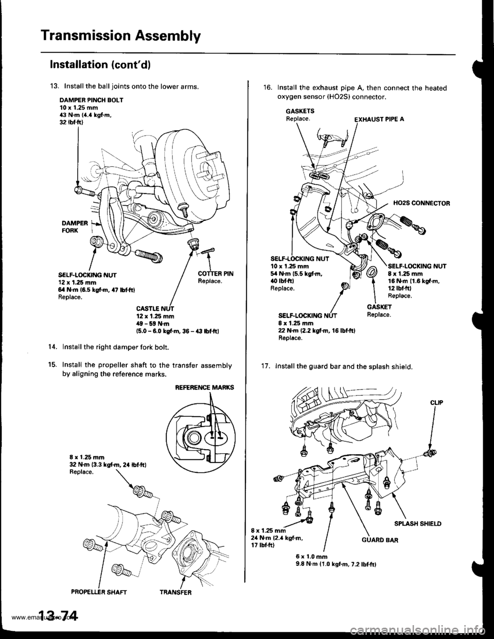
13. Installthe balljoints onto the lower arms.
DAMPER PINCH BOLT10 x 1.25 mm43 N.m {a.a kgf.m,32 rbfft)
SELF.LOCKING NUT'12 x 1.25 |nm6il N'm 16.5 kgtin, 47 lbtftlReolace.
Replace.
14.
PROPELI"ER SHAFT
13-74
12 x 1.25 mm,19 - 59 N.m(5.0 - 6.0 kgi.m, 36 - € lbfttl
Install the right damper fork bolt.
Install the propeller shaft to the transfer assembly
by aligning the reference marks.
E x 1.25 mr'|
15.
REFERENCE MARKS
32 N.m 13.3 kst m, 2a lbf.ftl
TRANSFER
Install the exhaust pipe A, then connect the heated
oxygen sensor (HO2S) connector.
GASKETSReplace.
HO2S CONNECTOR
10 x 1.25 mm5,1N.m 15.5 kgtm.() tbt filReplace.
SELF.LOCKING
SELF.LOCKING NUT8 x 1.25 mm16 N.rn 11.6 kg{.m,12lbtfr)Replace.
GASKETReplace.
8 x 1.25 rr|ln22 N.m (2.2 tgf.m, 16 lbl.ftlReplac6.
'17. Installthe guard bar and the splash shield.
SPLASH SHIEI.I)I x 1.25 mm24 N.m l2.a kgf.m.17 tbtft)GUARD BAR
6x1.0mm9.8 N.m (1.0 kgf.m, 7.2 lbf.ft)
www.emanualpro.com
Page 517 of 1395

Automatic Transmission
Special Tools . 14'2OescriptionGeneral Operation . .... 14 3Power Flow . . .. '14_6
Electronic Control System .. .. . . .. .14_15Hydraulic Control .. 14 24Hydraulic Flow....-....... .. . .... .. .. . 14_29Lock'up Syslem .. .'t4'39Electrical SystemComponenl Locdlrons 14 45
PCM Circuil Dragram (A/T Control Svstem)'97 Model ....................... . . .. - . ... .14-46'98Model ................. . ... .. .. .1450'99 00Models.... . .... . . . 1452
PCM Terminal Voltage/Measuring ConditionsA"/T Control System-'97Model ...... ..14'48A,/T Control System -'98 00 Models . . .. . . 14 54
Troubleshooting Procedures .. ..... ... - 14_56Svmotom to comoonent CharlEiectr,cal Syslem -'97 Model . . 14 60Electrical System -'98 - OO Models . .. . . 14_62Electrical Troubleshooting ('97 Model)Troubleshooting Flowaharts .... ..... . .. . . 14_64
Electrical Troubleshooting ('98 - 00 Models)Troubleshootinq Flowclt"n" .... . ....- . .14-93ElectricalTroublesliooting('99 00Models)Troubleshootino FlowchartO/D OFF Indicator Light Does Not Come On 14 131
O/D OFF Indicator Liaht On ConstantlY . . . .1!-132O/D OFF Indicator Light Does Not Come OnEven Though O/D Switch ls Pressed . .... - 14_133
Lock up Control Solenoid Valve A,/B AssemblyTest....................-......... . .14-135Replacement . .ll_135Shifr ControlSolenoid Valve Ay'B Assembl,Test .............................. . .. 14-136
Replacement..............- . .14'136Linear Solenoid AssemblYTest.............................................. .. .... . 14_137Replacement .. . 14138Marnshaftlcountershafl Speed SensorsReplacement ...-... 14_138A/T Gear Position SwitchTest ..........................-... . .. 14-139ReplacementA/T Gear Positionlndicator.................. 14-140
Valve Eodynepair ............................... ..... . . .. - . .. ... 14 192
Assembly .................... .. 1{_193
Valve CapsDesciiption....-........................ .. ...... 14194
tnspeition ................... .. 14' 195
N4ain Valve BodyDisassembly/lnspection/Reassemblv - ...... .. 14_196
Secondarv Valve BodYDisassemblv4nspectron/ReassemblY .. . 14 198
Reoulator Valve Bodvbisassembtv,lnspiction/Reassemblv . 14199
Servo EodvDisassembly/lnspection/Reassembly ... ....14'200
Lock'uo Valve BodYDis;ssembly/lnspection/Reassembly .... . 14_201
MainshaftDisassembly/lnspection/Reassembly .. .. .. ..14'202
Inspection ....-.............. ..11_203
Sealing RingsReilaceient ...... ..... . 14'204
CountershaftDisassembly/lnspection/Reassembly .. . . . . . 11-205
Disassembly/Reassemb|y . . ........ ...... . .. 14_206Inspedron ................ . .... . 14 207
One wav ClutchDisassembly/lnspection/ReassemblY ... 11_209
Sub-shaftDisassembly/lnspection/Reassembly ... . .. . 14-210
oisassembly/Re6ssembly . . ... .-...... . . ..14-211
Sub-shaft BearingsReplacement .......14'212
Clutchllfustrated Index .......... . . .14-213
Disassembly .... .. .....14-216Reassembfy .... . .. .. . 14'218
Differentialllfustrated Index " 14-222Backlash Inspection . .... . .14'223
Bearing Repiacement .. 11-223
Differe-ntial Carrier Replacement .. .. . . . .. ..11-2?4
OifSeal Replacement. . .. 14'225
Side Clearance lnspection . . - .. ... . - ...... . .. 11'226
Transmission Housing BearingsMainshaJVCountershaft EearingsRepfacement .......14221Sub'siralt Eearing Replacement . . . . . . . . . ..11'224
Toroue Converter Housing BearingsMainshattEearing/OilSe6lReplacement . .. l4229
Countershaft Bea;ing Replacement.. .... .. ..14-230
Input Test - '97 - 98 ModelsInput Test '99 - 00 Models
Symptom to-Component ChartHydraulic System ...............
Checking
Removal ...,lllustrated Index (4WD)
Interlock SystemInterlock ControlUnit lnputTest. -..... -.. .... . - 14 144* Key Interlock Solenoid Test .- .. . . . - . . . ..... 14_146* Shift Lock Solenoid Test ..............-.-. . .. . ... .... 14 147*Shift LockSolenoidReplacement...... .. . .. .. 14 148* park pin Switch Test ......... 14 119' Park Pin Switch Replacement- '97 - 98 Models ....... 14-150* Park Pin Swirch/Over Drive (O/Di SwitchReplacemenl '99-00Models . .. 14_151over-Drive (O/D) Switch {'99 00 [4odels]Test........_..................... .......14-152Hydr.ulic System
..............._............... t4 142.................................. 14-143
Control Lever AssemblyR6placement ......,.,Reverse ldler Gear
lllustrated lndex
.......... 14-230
14 231
11-231
1nsta1|ation ..................Park StopInspeclion/AdjustmenlTransfer AssemblY.......14.232
RoadTest.............-.... ........ .StallSpeedTest ....._........................ ....... 14-159Fluid Level......_................... 14'160
Disessembly .................... 14-235Transfer Drive Gear BearingReplacementTrans{er Driven Gesf Shaft BearingReplacementTransfer Housing Roller BearingReplacementTransfer Cov€r A Bearing Outer RaceReplacementTransfer Housing Bearing Outer RaceReplacement ......-..,,,,,.....ReassemblvTransmassaonBeassembly ... -.. .... .14 250
Torque Converier/Drive Plate . .-. .... .. . ... .....14_258
Transmissionlnstatlation .................. ....... 14'259
Cooler Flushing . . ......11-261ATF Cooler HosesConnection.................. ....... 14-266I Shift LeverRemoval/lnstallation . .. 14'261
Disassemblv/Reassemblv - '97 - 98 Models . . 14_264
Disassembli/Reassemblv -'99 - 00 Models . 14-269
Over'Orive (O/D) Switch WireClearanceAdjustment. - ... . . . .. .. . 14'270
Detent Spring Replscement . . -.. ... .14'271*Shift CableAdiustment ....... 14'272
Repfacement.............. . 11'273
14 15711-237
11-237
14-238
$-234
11-23914-240
Transmigrion
Inspeclron ....., ...........Transfer AssemblyRemova1,.,,,..............,lnstallalion ........... .. ...Transmission
14 164
14-16514,167
14-169
End Cover/Transmissio . 14'174Transmission Housing .... ... .. . . .... .. 14-176Torque Converter Housingly'alve Body.. - ... -. 14 178
lllustrated lndex (2WD)End Cover/Transmissio ....... 14 180Transmission Housing . . ... . .. .... ... 14'182Torque Convener Housing/r'alve Body ......- 14-184
End CovefRemovat ...................... ....... 14'186Transmission HousingRemoval ...................... .. 14_188Torque Convener HousingA/alve BodYRemovat ................-..... .-..... 14-190
www.emanualpro.com
Page 520 of 1395
Description
General Operation (cont'dl
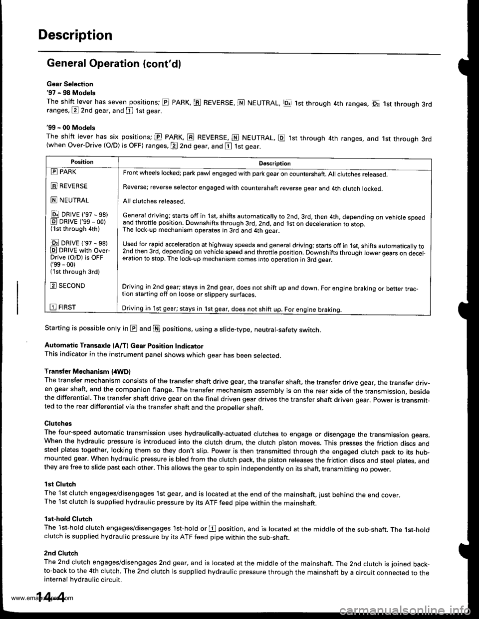
Gsar Selection'97 - 98 Models
The shift lever has seven positions; El PARK, ts REVERSE, N NEUTRAL, Ell 1st through 4th ranges, lpq 1st th.ough 3rdranges, P 2nd gear, and [ 1st gear
'99 - 00 Models
The shitt lever has six positions; El PARK, E REVERSE, E NEUTRAL. E ,lst through 4th ranges, and 1st through 3rd(when Over-Drive (O/D) is OFF) ranges. @ 2nd gear, and E 1st gear.
Starting is possible only in @ and @ positions. using a slide-type. neutral-safety switch.
Automatic Transaxle (A/T) Gear Position IndicatorThis indicator in the instrument panel shows which gear has been selected.
Transler Mochanism {4WD}
The transfer mechanism consists of the transfer shaft drive gear. the transfer shaft. the transfer drive gear, the transfer driv-en gear shaft, and the companion flange, The transfer mechanism assembly is on the rear side ot the transmission. besidethe differential. The transfer shaft drive gear on the final driven gear drives the transfer shaft driven qear. power is transmit-ted to the rear differential via the transfer shaft and the Drooeller shaft.
Clutches
The four-speed automatic transmission uses hydraulically-actuated clutches to engage or disengage the transmission gears.When the hydraulic pressure is introduced into the clutch drum, the clutch piston moves. This presses the friction discs andsteel plates together, locking them so they don't slip. Power is then transmifted through the engaged clutch pack to its hu$mounted gear. When hydraulic pressure is bled from the clutch pack, the piston releases the friction discs and steel plates, andthey are free to slide past each other. This allows the gearto spin independently on its shaft, transmitting no power.
lst Clutch
The 1st clutch engages/disengages lst gear, and is located at the end ofthe mainshaft, just behind the end cover.The 1st clutch is supplied hydraulic pressure by its ATF feed pipe within the mainshaft.
lst-hold Clutch
The 1st-hold clutch engages/disengages 1st-hold or E position, and is located at the middle of the sub-shaft. The 1st-holdclutch is supplied hydraulic pressure by its ATF feed pipe within the sub-shaft.
2nd Clutch
The znd ciutch engages/disengages 2nd gear, and is located at the middle of the mainshaft. The 2nd clutch is joined back-to-back to the 4th clutch. The 2nd clutch is supplied hydraulic pressure through the mainshaft by a circuit connected to theinternal hydraulic circuit.
PositionDescription
Reverse; reverse selector engaged with countershaft reverse gear and 4th clutch locked.
Allclutches released.
General driving; starts off in 1st, shifts automatically to 2nd, 3rd, then 4th, depending on vehicle speedand throftle position. Downshifts through 3rd,2nd, and lst on deceleration to stop.The lock-up mechanism operates;n 3rd and 4th gear.
used for rapid €cceleration at highway speeds and general driving; stans off in 1st, shifts automatically to2nd_then 3rd, dejending on vehicle speed and throttle position. Downshifts through lower gears on decel-eration to stop. The lock-up mechanism comes into operation in 3rd gear.
Driving in 2nd_gear; stays in 2nd gear, does not shift up and down. For engine braking or better trac_tion starting off on loose or slippery surfaces.
Driving in 1st gear; stays in 1st gear, does not shift up. For engine braking.
tll PARK
t!!l l|EvEn>E
E NEUTRAL
Ell DRrvE ('97 - sB)E DRrvE ('ss - oo)(1st through 4th )
E DRrvE {'97 - s8)O DRTVE with over-Drive (O/D) is OFF('99 - 00)(1st through 3rd)
E SECOND
E FIRST
14-4
www.emanualpro.com
Page 521 of 1395
3rd Clutch
The 3rd clutch engages/disengages 3rd gear, and is located at the end of the countershaft, opposite the end cover. The 3rd
clutch is supplied hydraulic pressure by its ATF feed pipe within the countershaft.
ilth Clutch
The 4th clutch engages/disengages 4th gear, as well as reverse gear, and is located at the middle of the mainshaft. The 4th
clutch is joined back-to-back to the 2nd clutch. The 4th clutch is supplied hydraulic pressure by its ATF feed pipe within the
mainshaft.
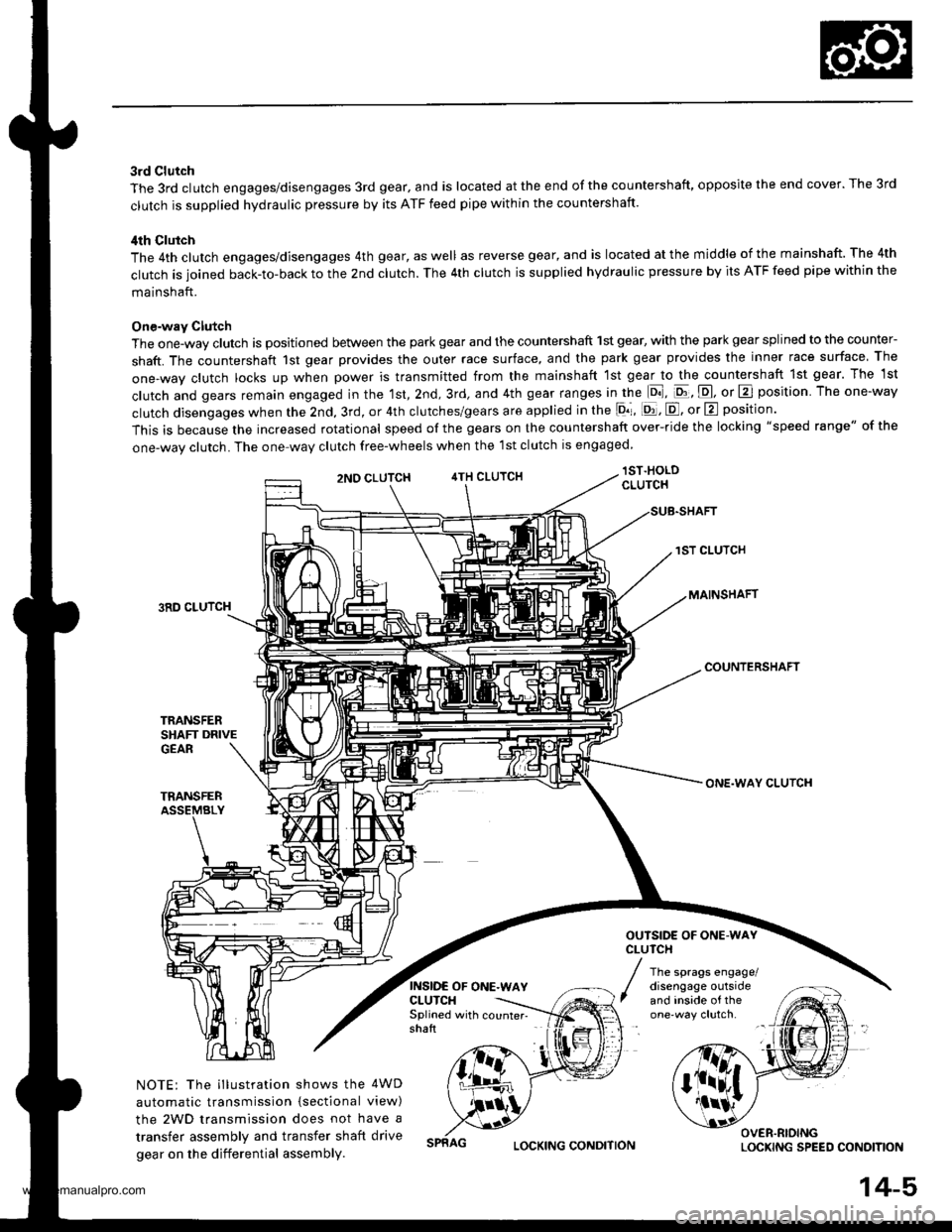
One-way Clutch
The one-way clutch is positioned between the park gear and the countershaft 1st gear, with the park gear splined to the counter-
shaft. The countershaft 1st gear provides the outer race surface, and the park gear provides the inner race surface The
one,way clutch locks up when power is transmitted from the mainshaft lst gear to the countershaft 1st gear. The 1st
clutch and gears remain engaged in the 1st, 2nd, 3rd, and 4th gear ranges in the lo], pt, E, or E position The one-way
clutch disengages when the 2nd, 3rd, or 4th clutches/gears are applied in the lor, [d, E, or E position'
This is because the increased rotational speed of the gears on the countershaft over-ride the locking "speed range" of the
one-wav clutch. The one-wav clutch free-wheels when the lst clutch is engaged
lST.HOLDCLUTCH
1ST CLUTCH
MAINSHAFT3RD CLUTCH
COUNTERSHAFT
TRANSFERSHAFT DRIVEGEAR
TRANSFERASSEMBLY
NOTE: The illustration shows the 4WD
automatic transmission {sectional view)
the 2WD transmission does not have a
transfer assembly and transfer shaft drive
gear on the differential assembly.
2NO CLUTCH4TH CLUTCH
INSIDE OF ONE.WAYCLUTCH
ONE.WAY CLUTCH
OUTSIDE OF ONE.WAYCLUTCH
The sprags engage/disengage outsideand inside of theSplined with counter- -
shaft
OVER.RIOINGLOCKING SPEED CONOITIONLOCKING CONDITION
14-5,
www.emanualpro.com
Page 523 of 1395
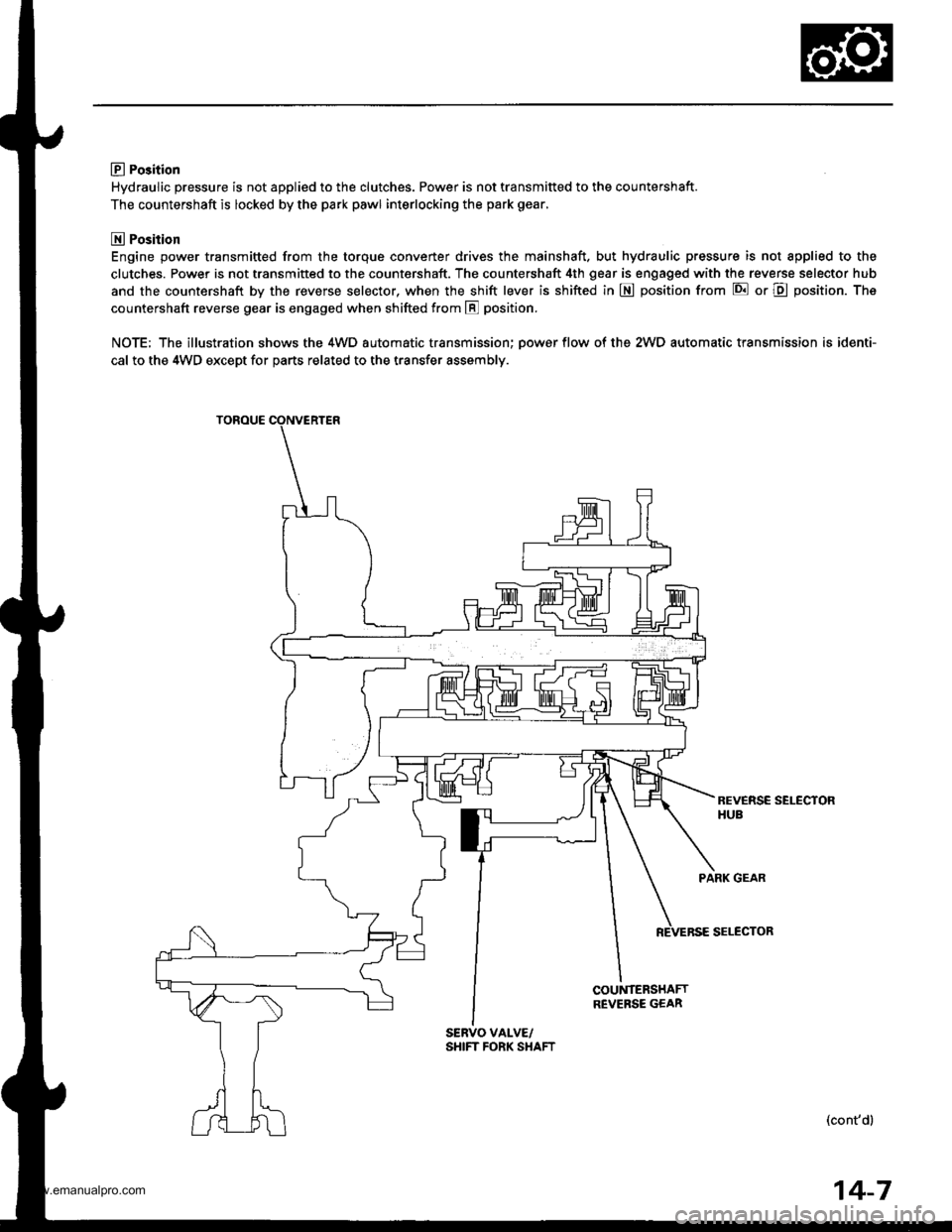
E Po3ition
Hydraulic pressure is not applied to the clutches. Power is not transmitted to the countershaft.
The countershaft is locked by the park pawl interlocking the park gear,
E Position
Engine power transmitted from the torque converter drives the mainshaft. but hydraulic pressure is not applied to the
clutches. Power is not transmitted to the countershaft. The countershaft 4th gear is engaged with the reverse selector hub
and the countershaft by the reverse selector, when the shift lever is shifted in E position from E or E position. The
countershaft reverse gear is engaged when shifted from E position.
NOTE; The illustration shows the 4WD automatic transmission; oower flow of the 2WD automatic transmission is identi-
cal to the 4WD exceDt for oarts related to the transfer assemblv.
PARK GEAR
SELECTOR
(cont'd)
COUNTERSHAFTREVEBSE GEAR
14-7
www.emanualpro.com
Page 524 of 1395
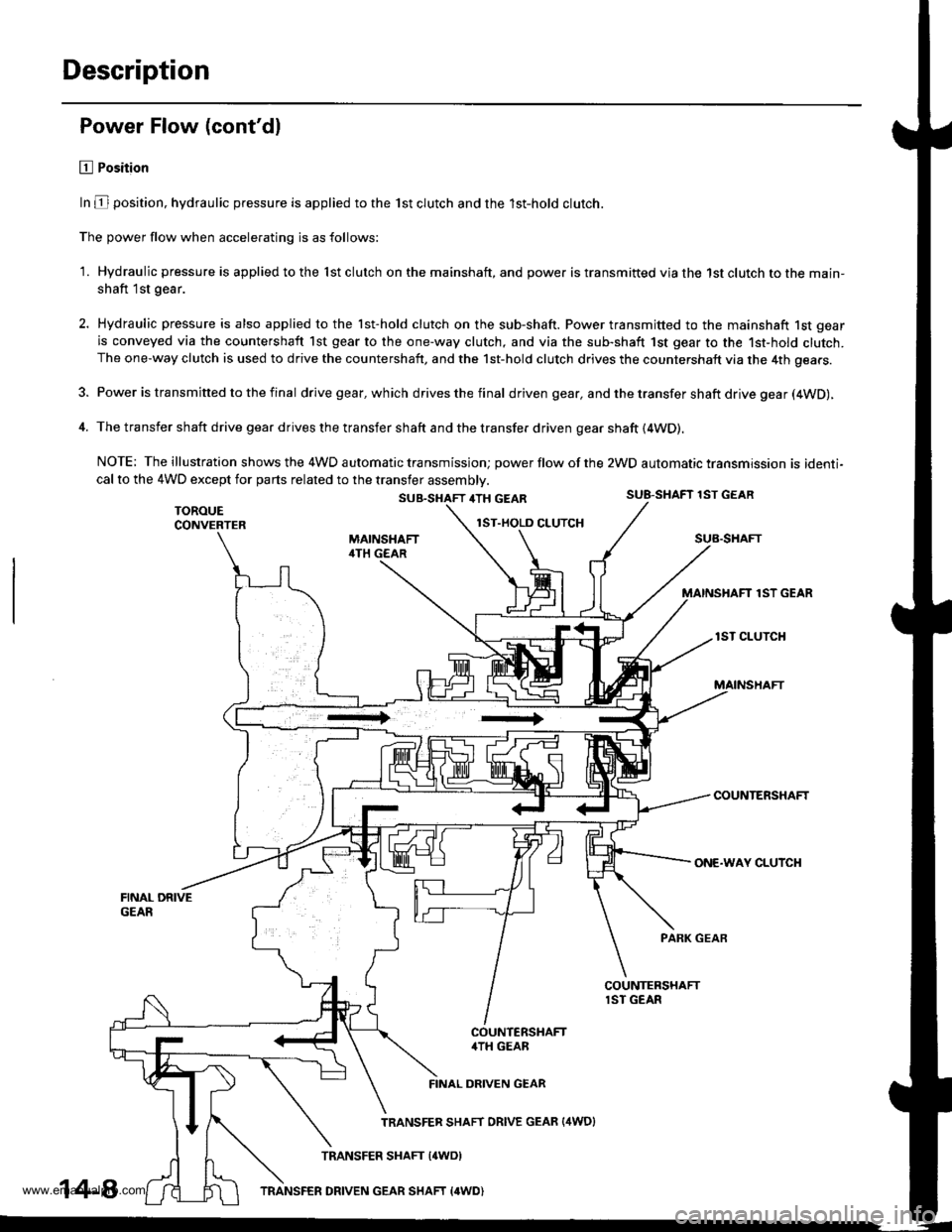
Description
Power Flow (cont'dl
E Position
In E position, hydraulic pressure is applied to the lst clutch and the lst-hold clutch.
The power flow when accelerating is as follows:
1. Hydraulic pressure is applied to the lst clutch on the mainshaft, and power is transmitted via the 1st clutch to the main-
shaft 1st gear.
Hydraulic pressure is also applied to the lst-hold clutch on the sub-shaft. Power transmitted to the mainshaft 1st gear
is conveyed via the countershaft 1st gear to the one-way clutch, and via the sub-shaft 1st gear to the 1st-hold clutch.The one-way clutch is used to drive the countershaft, and the 1st-hold clutch drives the countershaft via the 4th gears.
Power is transmitted to the final drive gear, which drives the final driven gear, and the transfer shaft drive gear (4WD),
The transfer shaft drive gear drives the transfer shaft and the transfer driven gear shaft (4WD).
NOTE; The illustration shows the 4WD automatic transmissjon; power flow ot the 2WD automatic transmission is identi-cal to the 4WD except for parts related to the transfer assembly.
SUB.SHAFT 4TH GEARSU8-SHAFT 1ST GEAR
4.
TOROUECONVERTERlST.HOLD CLUTCHSUB.SHAFT
1ST GEAR
lST CLUTCH
COUNTERSHAFT
ONE.WAY CLUTCH
FINAL DRIVEGEAR
PARK GEAB
COUNTERSHAFT4TH GEAR
FINAL DRIVEN GEAR
TRANSFER SHAFT ORIVE GEAR {4WD}
TRANSFER SHAFT {4WD}
14-8TRANSFER DRIVEN GEAR SHAFT {4WD)
www.emanualpro.com
Page 525 of 1395
2.
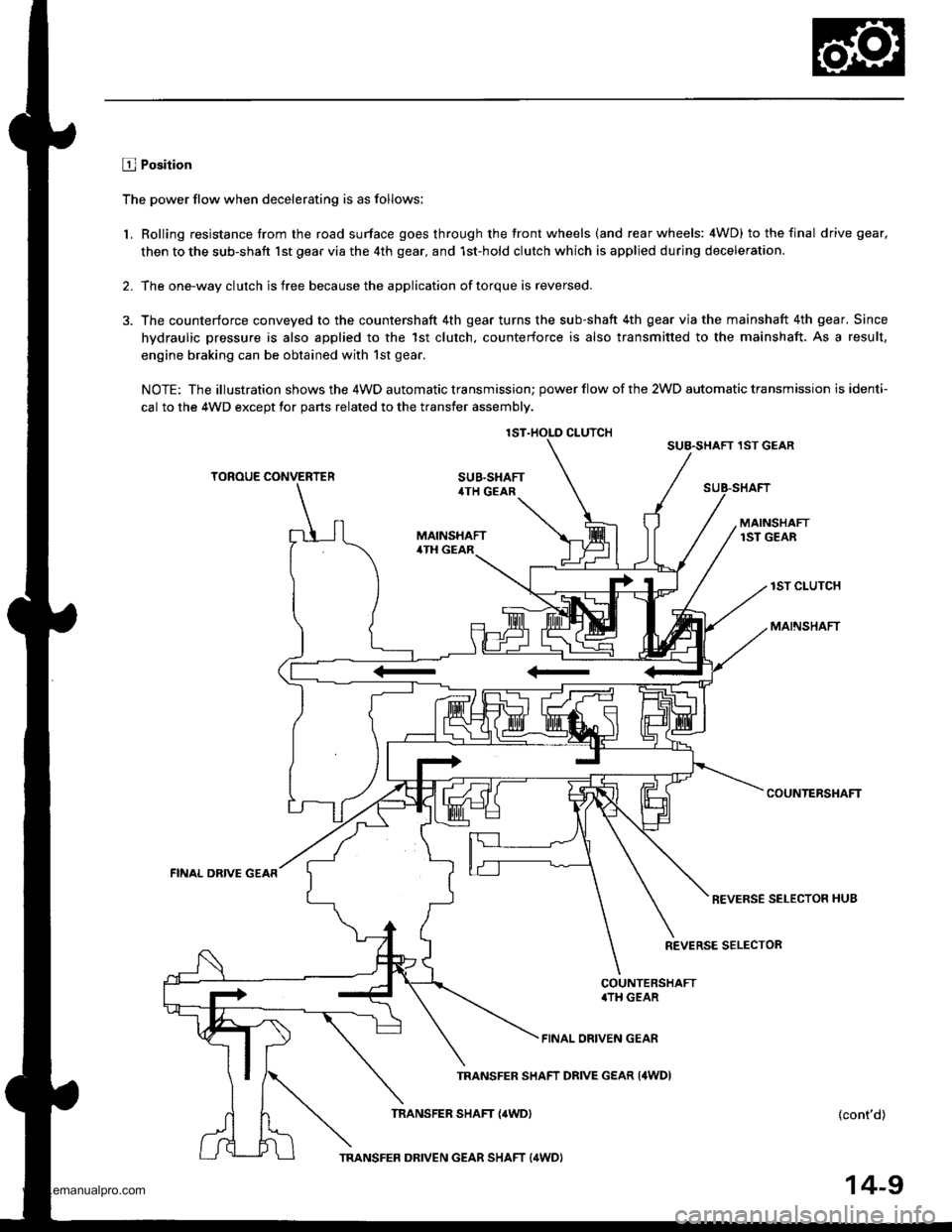
L
E Position
The power flow when decelerating is as follows:
Rolling resistance trom the road surface goes through the tront wheels (and rear wheels: 4WD) to the final drive gear.
then to the sub-shaft lst gear via the 4th gear. and 1st-hold clutch which is applied during deceleration.
The one-way clutch is free because the application of torque is reversed.
The counterforce conveyed to the countershaft 4th gear turns the sub-shaft 4th gear via the mainshaft 4th gear. Since
hydraulic pressure is also applied to the 1st clutch. counterforce is also transmitted to the mainshaft. As a result,
engine braking can be obtained with'lst gear.
NOTE: The illustration shows the 4WD automatic transmission; power flow of the 2WD automatic transmission is identi-
cal to the 4WD except tor parts related to the transfer assembly.
J.
SUB.SHAFT 1ST GEAR
TOROUE CONVERTER
FINAL DRIVE GEAR
SUB.SHAFT{TH GEAR
MAINSHAFTlST GEAR
lST CLUTCH
MAINSHAFT
COUNTERSHAFT
REVERSE SELECTOR HUB
REVERSE SELECTOR
COUNTERSHAFTIITH GEAR
FINAL ORIVEN GEAR
TRANSFER SHAFT DRIVE GEAR {4WDI
TRANSFEB SHAFT {{WD){cont'd}
lST.HOLD CLUTCH
TRANSFER DRIVEN GEAR SHAFT {,lWDl
14-9
www.emanualpro.com
Page 526 of 1395
Description
Power Flow lcont'd)
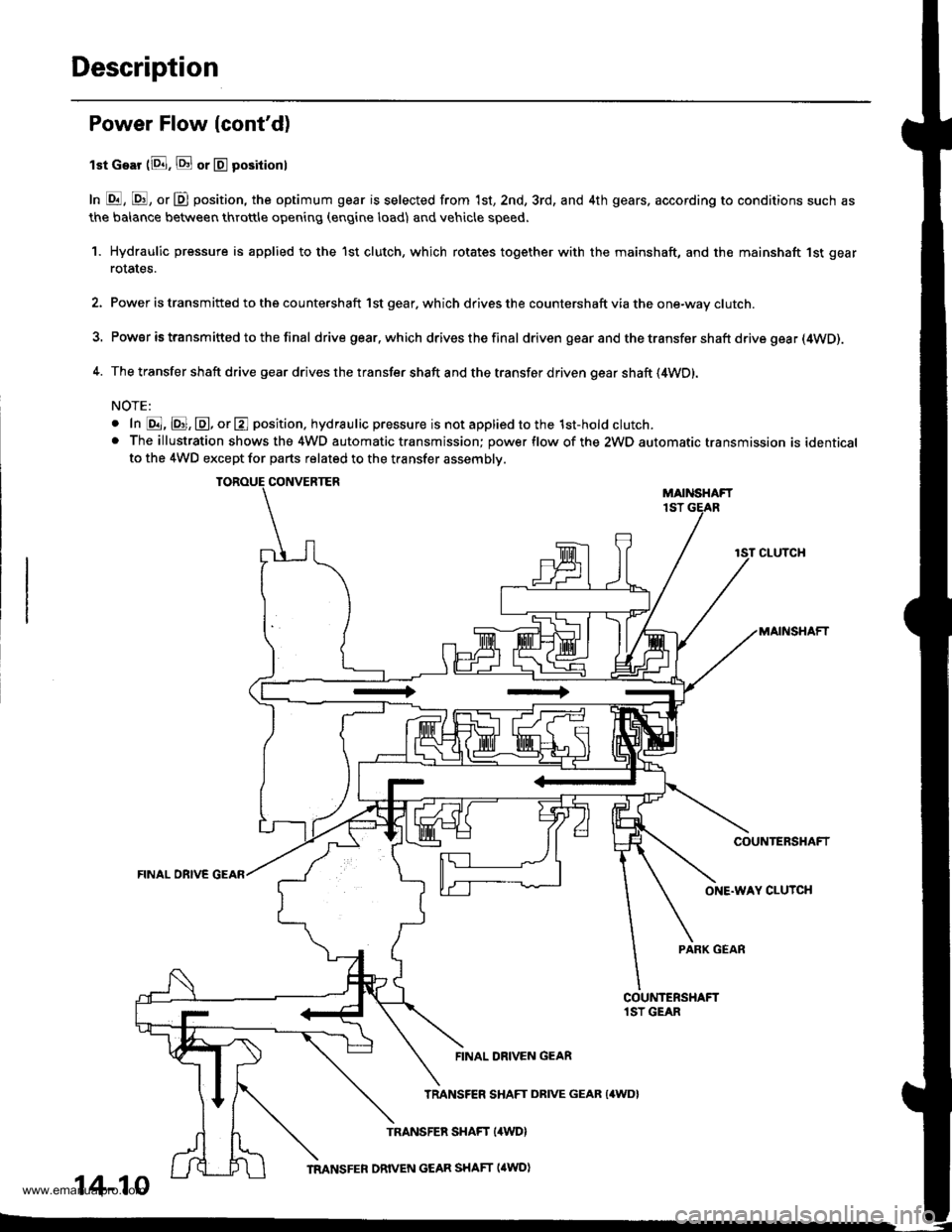
lst Gear (8. E or E positionl
In E, E, or D position, the optimum gear is selected from 1st, 2nd, 3rd, and 4th gears, according to conditions such as
the balance between throttle opening (engine load) and vehicle speed.
1. Hydraulic pressure is applied to the 1st clutch, which rotates together with the mainshaft, and the mainshaft 1st gear
rotates.
2. Power is transmitted to the countershaft 1st gear. which drives the countershaft via the one-way clutch.
3. Power is transm itted to the final drive gear.which drives the final driven gear and the transfer shaft drive gea r (4WD).
4. The transfer shaft drive gear drives the transfer shaft and the transfer driven gear shaft (4WD).
NOTE:
o In @, @, @, or E position. hydraulic pressure is not applied to the 1st-hold clutch.. The illustration shows the 4WD automatic transmission; power flow of the 2WD automatic transmission is identicalto the 4WD except for parts related to the transfer assembly.
CONVERTERMAIiISHAFT1ST
CLUTCH
MAINSHAFT
COUNTERSHAFT
FINAL OBIVE GEAR
ONE.WAY CLUTCH
PARK GEAR
FINAL DRIVEN GEAR
14-10
TRANSFER SHAFT DRIVE GEAR {4WD}
www.emanualpro.com
Page 527 of 1395
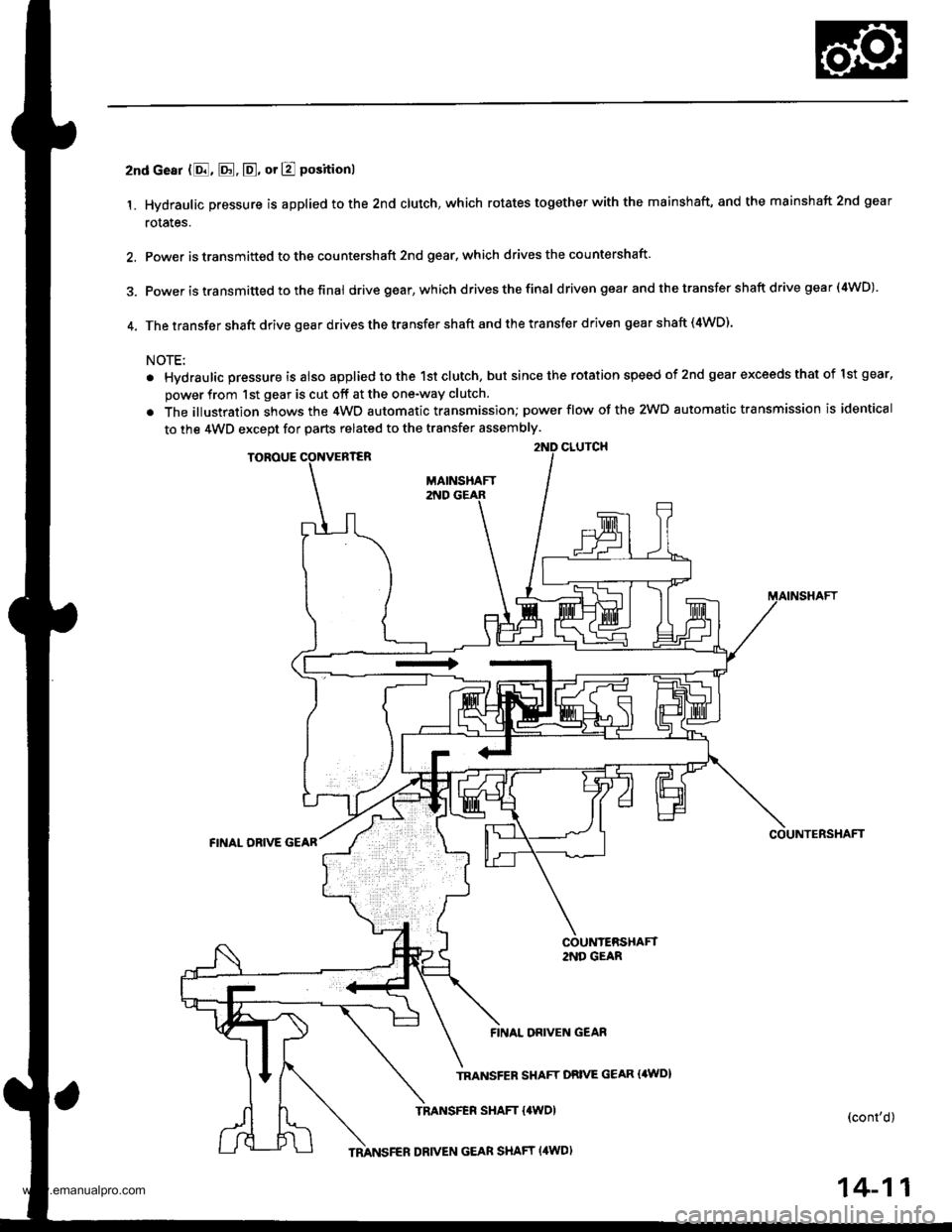
2nd cesr (8, E. E, or E positionl
1. Hydraulic pressure is applied to the 2nd clutch, which rotates together with the mainshaft, and the mainshaft 2nd gear
rotales.
2. Power is transmitted to the countershaft 2nd gear, which drives the countershaft
3. power is transmitted to the final drive gear, which drivesthefinal d riven gear and the transfer shaft drive gea r (4WD)
4. The transfer shaft drive gear drives the transfer shaft and the transfer driven gear shaft (4WD).
NOTE:
. Hvdraulic pressure is also applied to the 1st clutch, but since the rotation speed of 2nd gear exceeds that of lst gear.
power from 1st gear is cut off at the one-way clutch.
. The illustration shows the 4WD automatic transmission; power flow of the 2WD automatic transmission is identical
to the 4WD except for parts related to the transfer assembly.
CLUICHTOROUE
COUNTERSHAFTFINAL ORIVE GEAR
2NO GEAR
FINAL DRIVEN GEAF
TRANSFER SHAFT DBIVE GEAR {4WD}
TRANSFER SHAFT {4WDI(cont'd)
TMNSFER DRIVEN GEAR SHAFT (4WD)
14-11
www.emanualpro.com