wire HONDA CR-V 2000 RD1-RD3 / 1.G Workshop Manual
[x] Cancel search | Manufacturer: HONDA, Model Year: 2000, Model line: CR-V, Model: HONDA CR-V 2000 RD1-RD3 / 1.GPages: 1395, PDF Size: 35.62 MB
Page 1376 of 1395
)
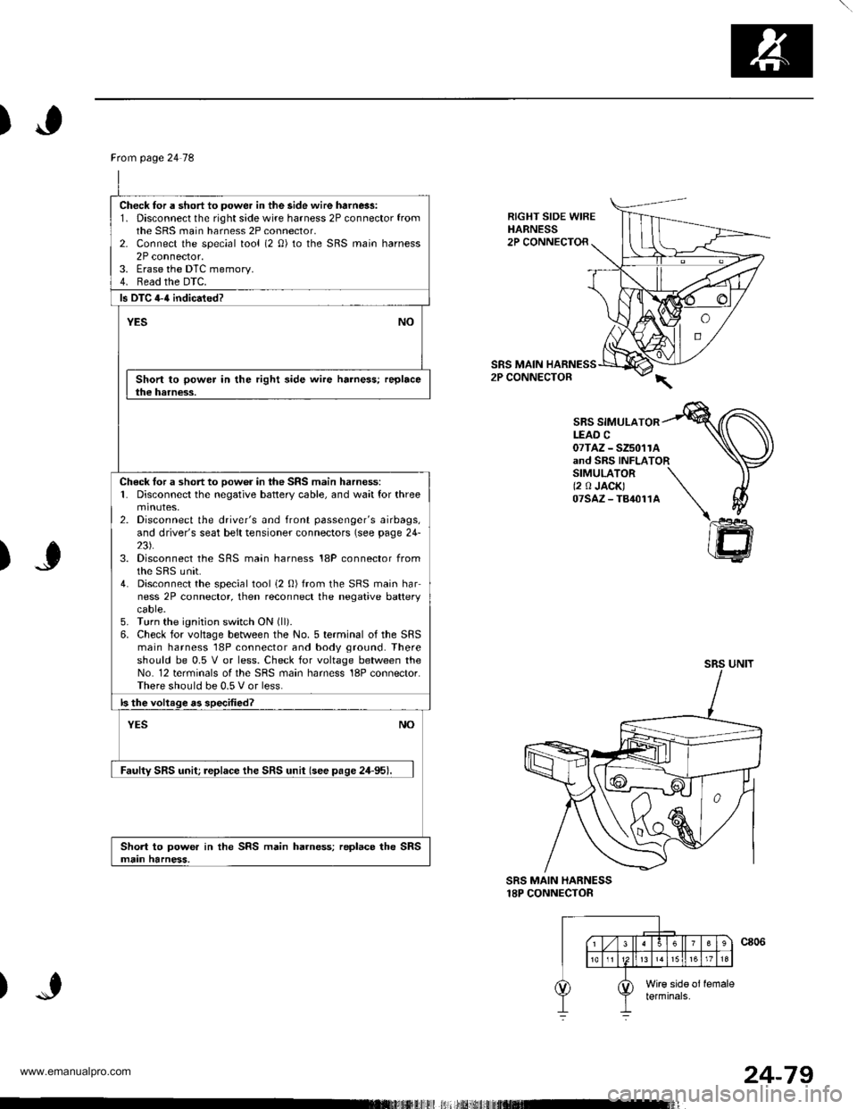
RIGHT SIDE WIREHARNESS2P CONNECTOR
SRS MAIN2P CONNECTOR
SBS SIMULATORLEAD C07TAZ - SZ5011Aand SRS INFLATORSIMULATOR \(2 0 JACK) \07sAz-T84011A \\
)J
)
@
SRS MAIN HARNESS18P CONNECTOR
Ftom page 24 78
Check for a short to power in the side wire harn6s:1. Disconnect the right side wire harness 2P connector fromthe SRS main harness 2P connector,2- Connect the special tool (2 0) to the SRS main harness2P connector.3. Erase the DTC memory.4. Read the DTC.
ls DTC 4-{ indicated?
YESNO
Short to power in the right side wire harness; replacethe harness.
Check tor a short to oow6r in the SRS main harness:1. Disconnect the negative battery cable, and wait for threemtnutes,2. Disconnect the driver's and front passenger's airbags,and driver's seat belt tensioner connectors (see page 24-23).3. Disconnect the SRS main harness 18P connector fromthe sRS unit.4. Disconnect the special tool i2 0) from the SRS main harness 2P connector, then reconnect the negative batterycaore.5. Turn the ignition switch ON (ll).
6. Check for voltage between the No. 5 terminal of the SRSmain harness 18P connector and body ground. Thereshould be 0.5 V or less. Check for voltage between theNo. 12 terminals of the SRS main harness 18P connector.There should be 0.5 V or less.
ls the voltage as specified?
NOYES
Faulty SRS unit; replace the SRS unit (see pase 24-95).
Short to power in the SRS main harness; replace the SRSmain harness.
24-79
www.emanualpro.com
Page 1377 of 1395
Troubleshooting
DTC 4-5
GAUTION: Whonever the ignition switch is ON fll). olhas be6n turned OFF for less than thrso minuter. becareful not to bump the SRS unit; the airbags couldaccidontally deploy and causo damage or iniurias.
\
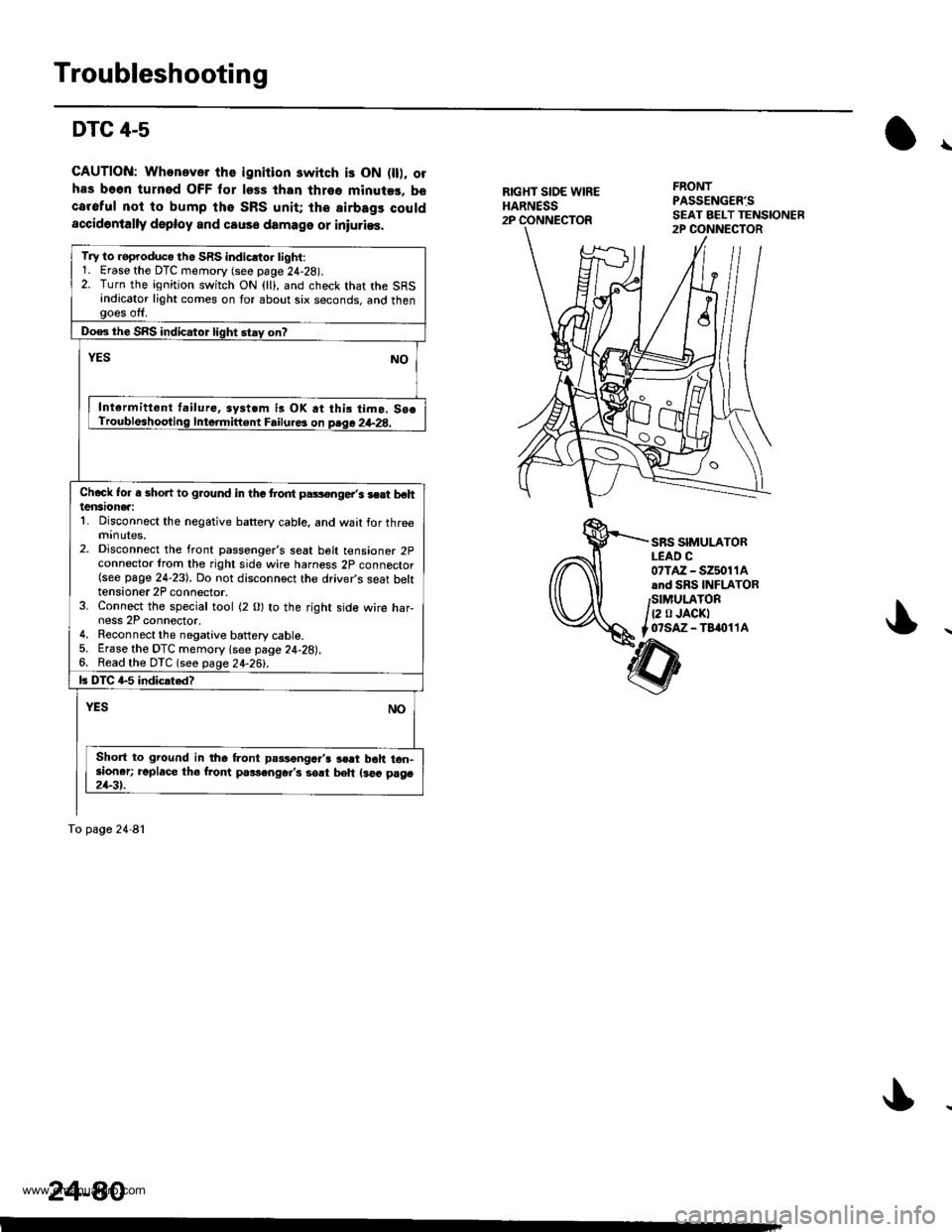
RIGXT SIOE WIREHARNESS2P
FRONTPASSENG€R'S
SRS SIMULATORLEAD C07lAz - s2501 1Aand SRS INFLATORSIMULATOR
t2 0 JACKTo?saz - Taaol 1A
Try to roproduco th. SRS indicrtor tighi:1. Erase the DTC memory (see page 24-28).2. Turn the ignition switch ON (ll), and check that the SRSindicator light comes on for about six seconds, and thengoes off.
Doe3 the SRS indicator light stay on?
YESNO
Int€rmittent t.ilurG, syst.m is OK at thi! timo. So€Troubleshooting Inte.mift€nt Failure3 on psqa 2+28.
Chcck Ior a shon to ground in the trodt pars€nge/s lert behtensionea:1. Disconnect the negative battery cable, and wait for threemrnutes.2. Disconnect the front passenger's seat belt tensioner 2pconnector trom the right side wire harness 2p connector(see page 24-23). Do not disconnect the driver's seat bektensioner 2P connector.3. Connect the special tool (2 0) to the right side wire har-ness 2P connector,4. Reconnect the negative battery cable.5. Erase the DTC memory lsee page 24-28).6. Read the DTC (seo page 24-26!-.
k DIC G5 indicated?
NOYES
Short to ground in the Lont passengc.'3 3€rt boh ton-sioner; replace tho from p.rlenger's sort beh ls€a page21-3t.
To page 24-81
24-80
www.emanualpro.com
Page 1378 of 1395
From page 24'80
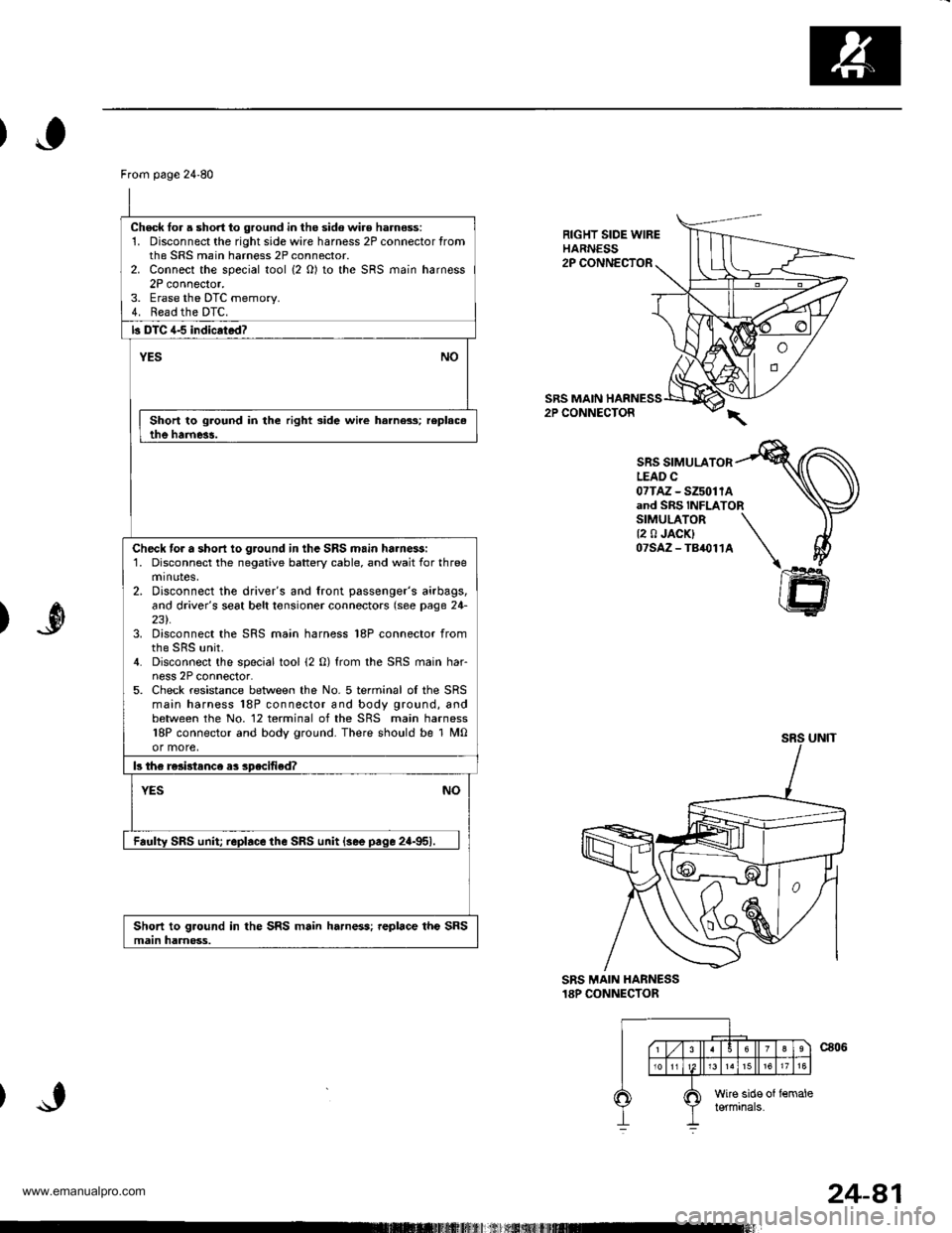
Check lor a short to ground in the sido wir€ harness:1. Disconnect the rightsidewire harness 2P connector fromthe SRS main harness 2P connector.2. Connect the special tool {2 O) to the SRS main harness2P connector.3. Erase the DTC memorv.4. Read the DTC.
b DTC 4-5 indicrtad?
YESNO
Short to ground in the right side wire harness; replac.the harne3!.
Check tor a short io ground in the SRS main ha.nessi1. Disconnect the negative battery cable, and wait for threeminotes,2. Disconnect the driver's and front passenger's airbags,and driver's seat belt tonsioner connectors (see page 24-231.3. Disconnect the SRS main harness 18P connector from
4. Disconnect the special tool (2 0) from the SRS main har-ness 2P connector.5. Check resistance between the No. 5 terminal oI the SRSmain harness 18P connector and body ground, andbetween the No. 12 terminal of the SRS main harness18P connector and body ground. There should be 1 M0or more,
b th€ re3i3tance as specified?
NOYES
Faulty SRS unit replace the SRS unit {see pace 2a-951.
Short to ground in the SRS main harness; replace the SRSmain harnoss.
RIGHT SIDE WIREHARNESS2P CONNECTOR
SRS MAIN HARNESS2P CONNECTOR
SRS SIMULATORLEAD C07TAz - SZ5011Aand SRS INFLATORSIMULATOR \{2 0 JACK} \07SAZ-TB,O114 \I
ffi
)
SRS MAIN HANNESS18P CONNECTOR
24-81
www.emanualpro.com
Page 1389 of 1395
Gable Reel
Replacement (cont'dl
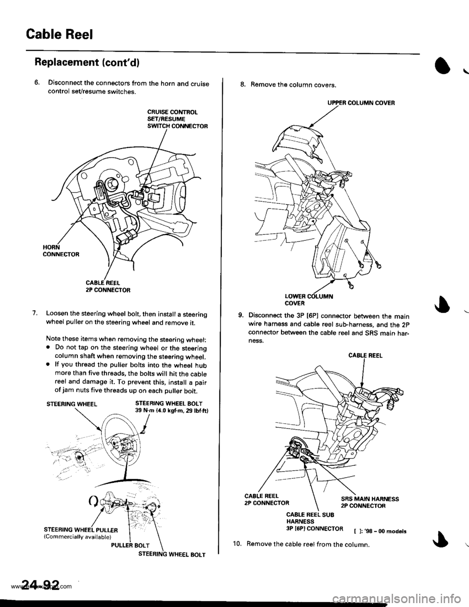
6, Disconnect the connectors from the horn and cruisecontrol sevresume switches.
cRursE coNtRoLSET/RESUMESWITCH CONNECTOR
1.Loosen the steering wheel bolt, then install a steeringwheel puller on the steering wheel and remove it.
Note these items when removing the stee.ing wheel:. Do not tap on the steering wheel or the steeringcolumn shaft when removing the steering wheel,. lf you thread the puller bolts into the wheel hubmore than five threads, the bolts will hit the cablereel and damage it. To prevent this. install a pair
of jam nuts five threads up on each puller bolt.
STEERING WHEEL BOLT39 N.m 14.0 kgf.m. 29 lbf.ftlSTEERING WHEEL
STEERING
2P CONNECTOR
24-92
8. Remove the column covers,
Disconnect the 3P [6P] connector between the mainwire harness and cable reel sub-harness, and the 2pconnector between the cable reel and SRS main har-ness.
CAALE REEL SU8HARNESS3P l6Pl CONNECTOR [ ]:,98_00modets
10. Remove the cable reelfrom the cotumn,
COVER
www.emanualpro.com
Page 1390 of 1395
)o
NOTE:
. Before installing the steering wheel, the front
wheels should be aligned straight ahead.
. Be sure to install the harness wires so that they
are not pinched or interfering with other parts.
. After reassemblv, confirm that the wheels are
still turned straight ahead and that the steering
wheel spoke angle is correct (road test). lf minor
spoke angle adjustment is necessary, do so only
by adjusting the tie-rods, not by removing and
repositioning the steering wheel,
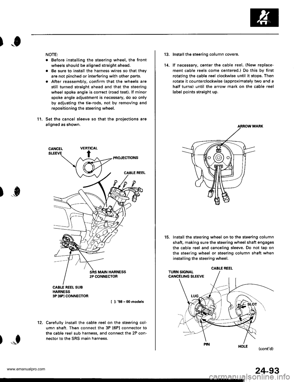
11. Set the cancel sleeve so that the projections are
aligned as shown.
PR(NECNONS
I l: 38 - 00 models
Carefully install the cable reel on the steering col-
umn shaft. Then connect the 3P t6Pl connector to
the cable reel sub harness, and connect the 2P con-
nector to the SRS main harness.
RIC
t
VEAL
)...0
't2.
24-93
13.
14.
Install the steering column covers.
lf necessary, center the cable reel. {New replace-
ment cable reels come centered,l Do this by first
rotating the csble reel clockwise until it stops, Then
rotate it counterclockwise (approximately two and a
half turns) until the arrow mark on the cable reel
label points straight up.
Install the steering wheel on to the steering column
shaft, making sure the steering wheel shaft engages
the cable reel and canceling sl€eve. Do not tap on
the steering wheel or steering column shaft when
installing the steering wheel.
(cont'd)
t5.
CABLE REEL
www.emanualpro.com
Page 1392 of 1395
SRS Unit
).0Replacement
CAUTION:
. Before disconnecting any part of the SRS wire har-
nesg, disconnect the airbag connoctors (and soat beh
tensioner connectorsl.
. During installation or replacament, do not bump(impact wrench, hammer etc.) the area near the SRS
unit.
Do not damage the SFS unit terminalg or connsc-
lors.
Do not disassemble the SRS unit it has no saryice-
able parts,
Store the SRS unit in a clean, dry area.
Do not use any SRS unit which has been subiected
to water damage or shows signs ot being dropped orimproperly handlgd, such as dents, cracks or defor-
mation.
Disconnect the battery negative cable, then discon-
nect the positive cable from the battery, andwaitat
least three minutes.
Disconnect the airbag connectors (and seat belt ten-
sioner connectors). (When disconnected, the airbag
and seat belt tensioner connectors are automatical-
ly shorted.)
Driver's Side:
. Remove the access panel from the steering
wheel, then disconnect the 2P connector
between the driver's airbag and cable reel (see
page 24-231.
Front Passenger's Side:. Disconnect the 2P connector between the frontpassenger's airbag and SRS main harness (see
page 24-231.
Soat Beh Tensionor ('98 - 00 modelsr:. Remove the left and right center pillar lower trimpanels (see section 20).
. Disconnect the seat belt tensioner 2P connectors
from the left side wire harness (driver's side) and
the right wire harness (front passenger's side)(see page 24'231.
2.
a
a
'1.
)
)o
24-95
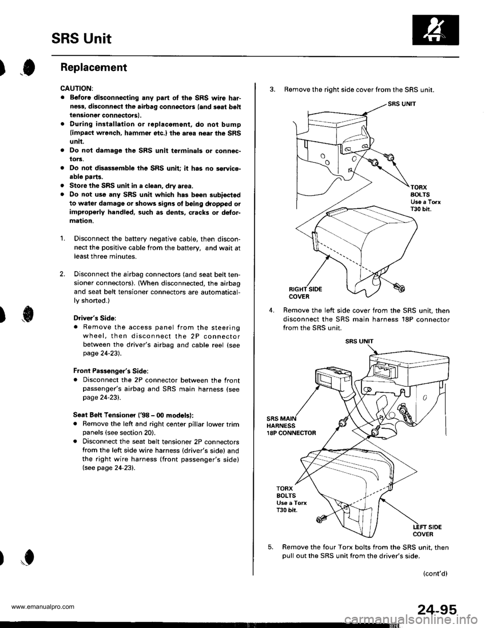
3. Remove the right side cover from the SRS unit.
SRS UNIT
TORXAOLTSUse a TorxT30 bir.
COVER
Remove the left slde cover from the SRS unit. then
disconnect the SRS main harness 18P connector
from the SRS unit.
sRsHARNESS18P CONNECTOR
TORXBOLTSUs€ a TorxT30 bir.
stoECOVER
Remove the four Torx bolts from the SRS unit. then
oull out the SRS unit from the driver's side.
(cont'd)
www.emanualpro.com
Page 1393 of 1395
SRS Unit
Replacement (cont'dl
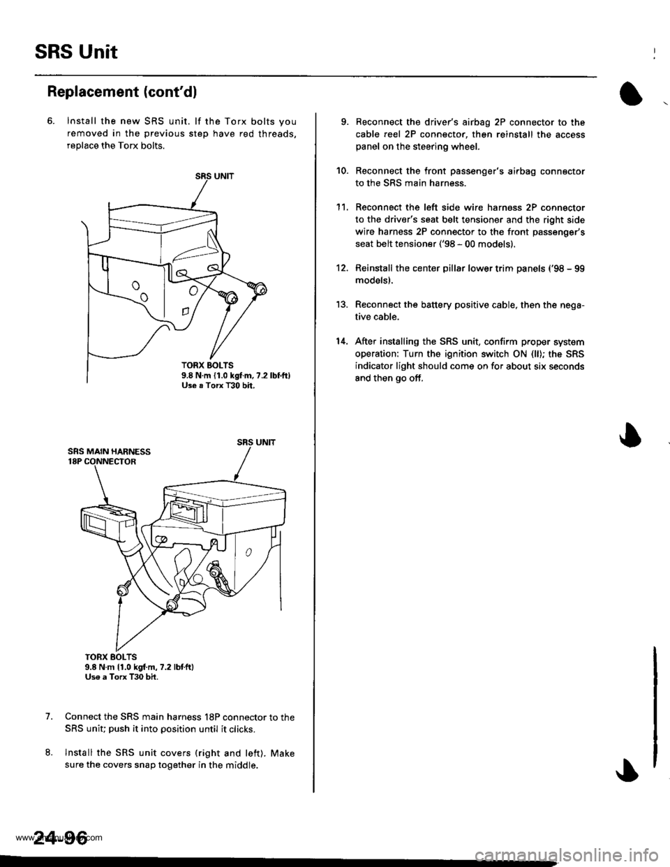
6. lnstall the new SRS unit. lf the Torx bolts you
removed in the previous step have red threads,
replace the Torx bolts.
TORX BOLTS9.8 N.m 11.0 kgf.m,7.2 lbtft)Uso a Torx T30 bit.
Connect the SRS main harness l8P connector to the
SRS uniu push it into position until it clicks.
Install the SRS unit covers (right and left). Make
sure the covers snap together in the middle.
7.
8.
TORX BOLTS9.8 N.m {1.0 kgf.m, ?.2Use . Torx T30 bh,
SRS UNIT
24-96
-
9. Reconnect the driver's aibag 2P connector to the
cable reel 2P connector, then reinstall the access
panel on the steering wheel.
Reconnect the front passenger's airbag connector
to the SRS main harness.
Reconnect the left side wire harness 2P connector
to the driver's seat belt tensioner and the right side
wire harness 2P connector to the front passenger's
seat belt tensioner ('98 - 00 models).
Reinstall the center pillar lower trim panels {'98 - 99
modelsl.
Reconnect the battery positive cable, then the nega-
tive cable.
After installing the SRS unit, confirm proper system
operation: Turn the ignition switch ON (ll); the SRS
indicator light should come on for about six seconds
and then go off,
10.
1't.
12.
13.
14.
www.emanualpro.com
Page 1394 of 1395
Airbag/Seat Belt Tensioner
)Disposal
)
Before scrapping any airbags {and seat belt tansioners)
(including those in a whole vehicle to be scrappedl. the
airbags (and seat belt tensioners) must be deployed. lf
the vehicle is still within the warrantv oeriod the Honda
District Service Manager must give approval and/or spe-
cial instructions, before you deploy the airbags (and seat
belt tensioners). Only after the airbags {and seat belt ten-
sioners) have been deployed (as the result of vehicle col-
lision, for example), can they be scrapped.
lf the airbags (and seat belt tensioners) appear intact
(not deployed), treat them with extreme caution.
Follow this procedure:
Doploying tho Airbags (and Soat B6li Ten3ione6):
ln-vehicle
lf an SRS vehicle is to be entirely scrapped, its airbags(and seat belt tensioners) should be deployed while still
in the vehicle. The airbags (and seat belt tensioners)
should not be considered as salvageable parts and
should never be installed in another vehicle.
@ confirm that each airbag {and seat belt
tonsiongr) i3 ggcurely mountod; othgrwise, severe per-
sonal iniury could result from d6ploym6nt,
1. Disconnect the battery negative cable, then discon-
nect the oositive cable.
Confirm that the special tool is functioning properly
by following the check procedure on the tool label
or on page 24-98.
Remove the access panel, then disconnect the 2P
connector between the driver's airbag and the cable
reel (see page 24-23).
Remove the glove box, then disconnect the 2P con-
nector between the front passenger's airbag and
SRS main harness (see page 24-23).
Remove the center pillar lower trim panel, then dis-
connect the 2P connector between the seat belt ten-
sioner and side wire harness ('98 - 00 models) (see
page 24-231.
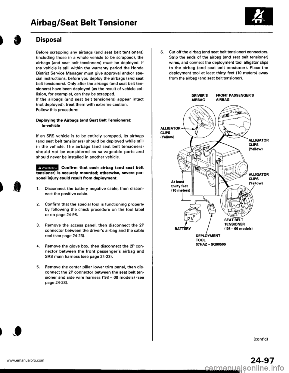
6. Cut off the airbag (and seat belt tensioner) connectors.
Strip the ends of the airbag (and seat belt tensioner)
wires. and connect the deployment tool alligator clips
to the airbag (and seat belt tensioner). Place the
deployment tool at least thirty feet (10 meters) away
from the airbao (and seat belt tensioner),
DRIVER'S FRONTPASSENGER'SAIBBAG AIRBAG
AI.IIGATORcuPslY6llowl
At lcastthirty feot
110 motersl
(cont'd)
24-97
www.emanualpro.com
Page 1395 of 1395
Airbag/Seat Belt Tensioner
1.
Disposal (cont'dl
Connect a 12 volt battery to the tool'
. It the green light on the tool comes on, the air-
bag igniter circuit is defective and cannot deploy
the airbag. Go to Damaged Airbag Special
Procedure.
.lftheredlightonthetool comes on, the airbag is
ready to be deployed.
Push the tool's deployment switch. The airbag
should deploy (deployment is both highly audible
and visible; a loud noise and rapid inflation of the
bag, followed by slow deflation).
. lf the airbags deploy and the green light on the
tool comes on, continue with this procedure.
. lf an airbag doesn't deploy, yet the green light
comes ON, its igniter is defective. Go to Dam-
aged Airbag Special Procedure.
. During deployment, the airbag can become hot
enough to burn you, Wait thirty minutes after
deployment before touching the airbag.
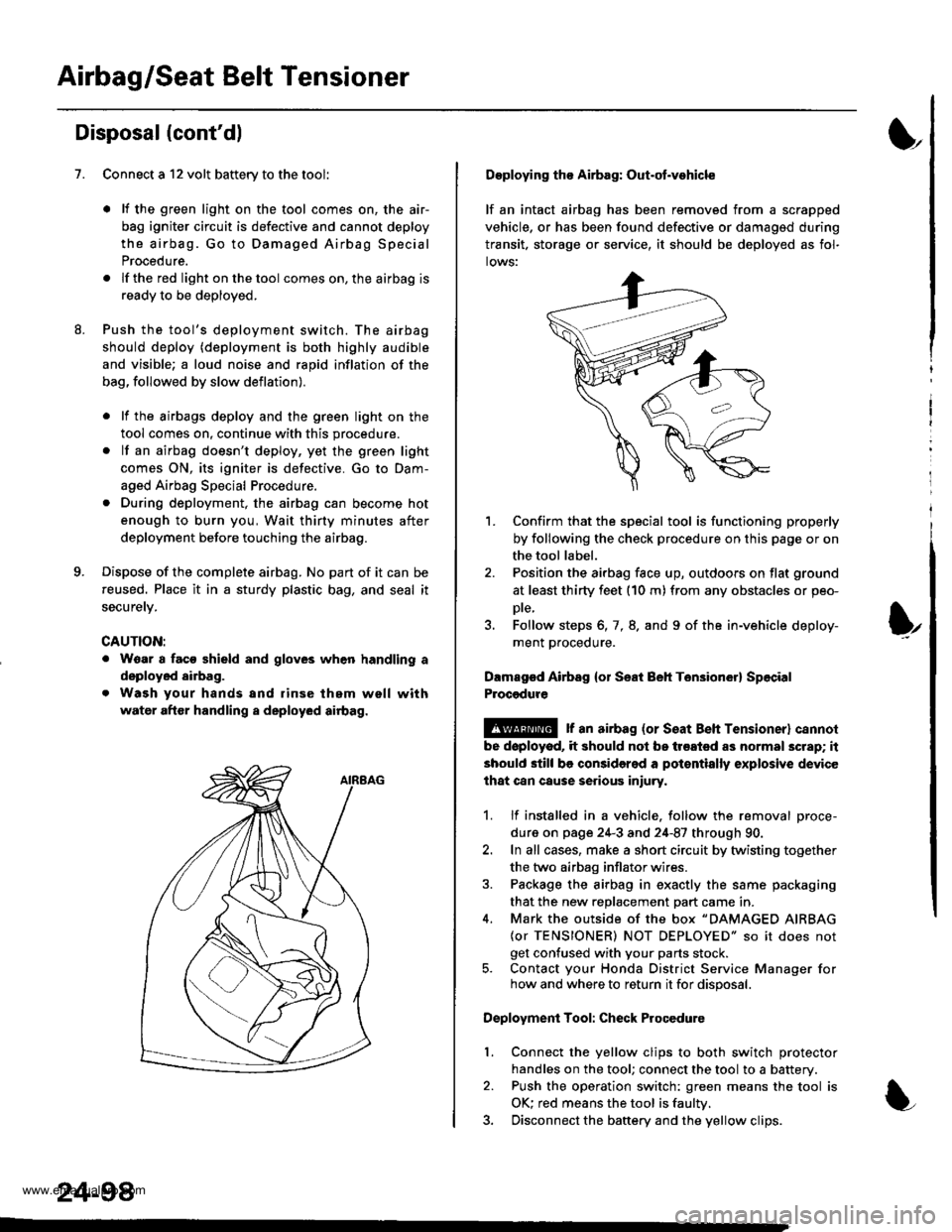
Dispose of the complete airbag. No part of it can be
reused. Place it in a sturdy plastic bag, and seal it
securety.
CAUTION:
. Wear a faco shield and gloves when handling a
deployed airbag.
. Wash your hands and rinse them well with
water after handling a deployed airbag.
24-98
Deploying tho Airbag: Out-ot.vohicle
lf an intact airbag has been removed from a scrapped
vehicle, or has been found defective or damagsd during
transit. storage or seryice, it should be deployed as fol-
lows:
'L Confirm that the special tool is functioning properly
by following the check procedure on this page or on
the tool label.
2. Position the airbag face up, outdoors on flat ground
at least thirty feet (10 m) from any obstacles or peo-
Dte,
3. Follow steps 6, 7, 8. and 9 of the in-vehicle deploy-
ment proceoure.
Dlmaged Airbsg {or Seat Beh Ten3ion6r} Sp6cial
Procgdure
!@ r an airbag {or seat Beh rensioner} cannol
be doployod, it should not be treated as normal scrap; it
should still be considered a pot€ntially explosive device
lhat can cause serious iniury.
1. lf installed in a vehicle. follow the removal proce-
dure on page 24-3 and 24-87 through 90.
2. In all cases, make a short circuit by twisting together
the two airbag inflator wires.
3. Package the airbag in exactly the same packaging
that the new reDlacement Dart came in.
4. Mark the outside of the box "DAMAGED AIRBAG
{or TENSIONER) NOT DEPLOYED" so it does not
get confused with your parts stock.5. Contact your Honda District Service Manager forhow and where to return it for disposal.
Deployment Tool: Check Procedure
Connect the yellow clips to both switch protector
handles on the tool; connect the tool to a battery.
Push the operation switch: green means the tool is
OK: red means the tool is faultv.
Disconnect the baftery and the yellow clips.
I
t
l.
www.emanualpro.com