Disc HONDA CR-V 2000 RD1-RD3 / 1.G Service Manual
[x] Cancel search | Manufacturer: HONDA, Model Year: 2000, Model line: CR-V, Model: HONDA CR-V 2000 RD1-RD3 / 1.GPages: 1395, PDF Size: 35.62 MB
Page 282 of 1395
PGM-FI System
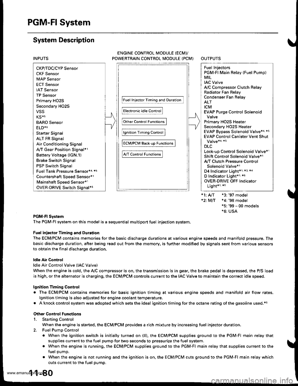
System Description
INPUTS
CKP/TDC/CYP Sensor
CKF Sensor
MAP Sensor
ECT Sensor
IAT Sensor
TP Sensor
Primary HO2S
Secondary H02S
vss
KS*5
BARO Sensor
ELD*6
Starter Signal
ALT FR Signal
Air Conditioning Signal
Ay'T Gear Position Signal*1
Baftery Voltage (lGN.1)
Brake Switch Signal
PSP Switch Signal
Fuel Tank Pressuae Sensor*4. *5
Countershaft Speed Sensor*1
Mainshaft Speed Sensor*r
OVER-DRIVE Switch Signal*s
ENGINE CONTROL MODULE (ECM)/
POWERTRAIN CONTROL MODULE (PCM) OUTPUTS
|iuel 1"j""- Th,rhg ""d Drrafr";-l
Et*-.nt"tdt"cont.orl
to,r*,c;;trffi;]
l.----.---:. .Lrgnrnon |lmrng Lonrror I
Ecir/PcM B*k',p Fr""il]
m;"t-ll-r*'io*l
Fuel Injectors
PGM-Fl Main Relay (Fuel Pump)
MIL
IAC Valve
Ay'C Compressor Clutch Relay
Radiator Fan Relay
Condenser Fan Relay
ALT
tcM
EVAP Purge Control Solenoid
Valve
Primary HO2S Heater
Secondary H02S HeaterEVAP Bypass Solenoid Valve*a *5
EVAP Control Canister Vent Shut
DLC
Lock-up Control Solenoid Valve*l
Shift Control Solenoid Valve*1
Ay'T Clutch Pressure Control
Solenoid Valve*1
D4 Indicator Light'1 *3, *a
D Indicator Light,l *5
OVER-DRIVE OFF Indicator
Lighl*t *:
*1: A/T {3:'97 model'2: M/f +4:'98 model*5: '99 - 00 models"6: USA
PGM-Fl System
The PGM-Fl system on this model is a sequential multiport fuel injection system.
Fuel iniecior Timing and Duration
The ECM/PCM contains memories for the basic discharge durations at various engine speeds and manifold pressure. The
basic discharge duration, after being read out from the memory, is further modified by signals sent from various sensors
to obtain the final discharge duration.
ldle Air Control
ldle Air Control Valve (lAC Valve)
When the engine is cold, the Ay'C compressor is on, the transmission is in gear, the brake pedal is depressed, the P/S load
is high, or the alternator is charging, the ECM/PCM controls current to the IAC Valve to maintain the correct idle speed.
lgnition Timing Control
o The ECM/PCM contains memories for basic ionition timing at various engine speeds and manifold air flow rates.
lgnition timing is also adjusted for engine coolant temperature.
. A knock control system was adopted which sets the ideal ig nition timing for the octane rating of the gasoline used.*s
Other Control Funstions
1. Starting Control
When the engine is started. the ECM/PCM provides a rich mixture by increasing fuel injector duration.
2. Fuel Pump Control
. When the ignition switch is initially turned on (ll). the ECMiPCM suppli€s ground to the PGM-FI main relay that
supplies current to the fuel pump for two seconds to pressurize the fuel system.
. When the engine is running, the ECM/PCM supplies ground to the PGM-FI main relay that supplies current to the
fuel oumo.
. When the engine is not running and the ignition is on, the ECM/PCM cuts ground to the PGM-FI main relay which
cuts current to the fuel pump.
1 1-80
www.emanualpro.com
Page 286 of 1395
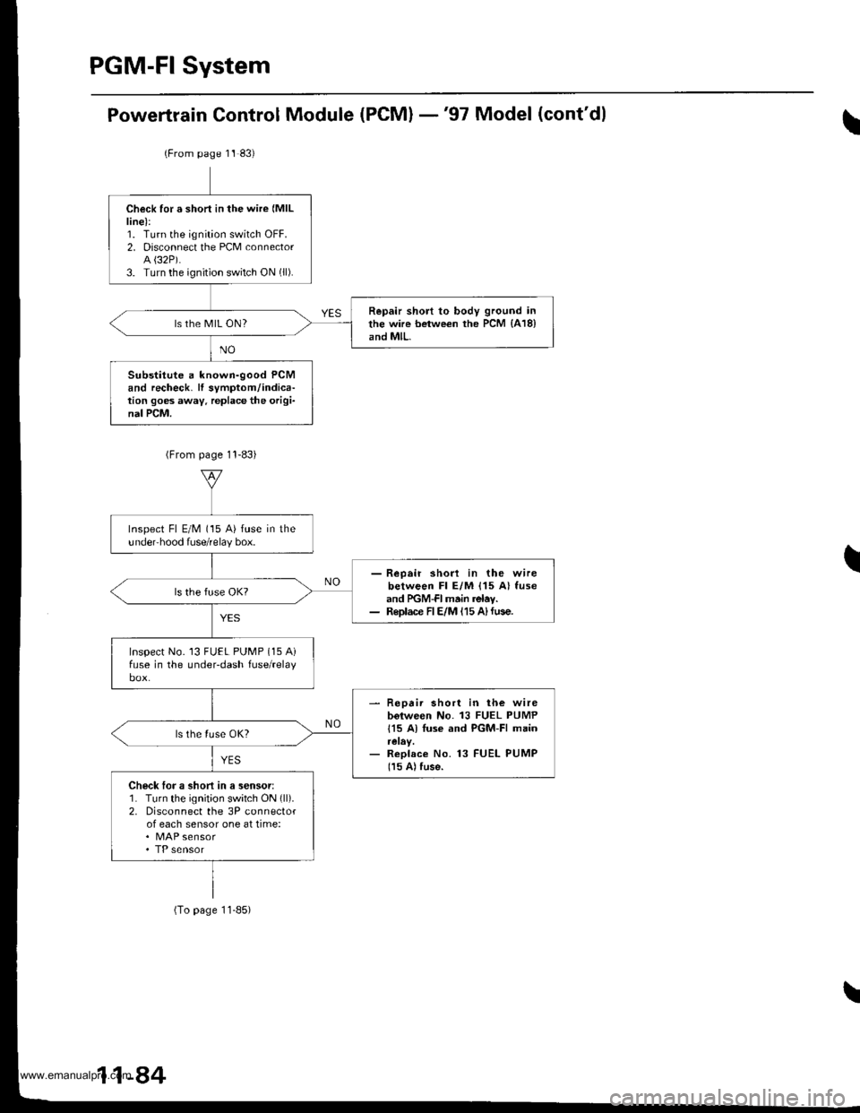
Powertrain Control Module (PCM) -'97 Model (cont'dl
(From page 11 83)
Check for a short in the wire (MlL
line):1. Turn the ignition switch OFF.2. Disconnect the PCM connectorA {32P).3. Turn the ignition switch ON (ll).
Repair short to body ground inthe wire between the PCM {418}and MlL.ls the MIL ON?
Substitute a known-good PCMand recheck. lf symptom/indica-tion goes away. replace the origi-nal PCM.
Inspect Fl E/M (15 A) fuse in theundeFhood fuse/relay box.
- Reoair shod in the wirebetween Fl E/M {15 A} fuseand PGM-FI main relav.- Replace FIE/M 115 A)fuse.
Inspect No. 13 FUEL PUMP (15 Aifuse in the underdash fuse/relay
- Repair short in lh€ wirebolween No. 13 FUEL PUMP
115 A) Iuse and PGM-FI main
- Replace No. 13 FUEL PUMP
115 A) fuse.
Check loJ a short in a sensor:1. Turn the ignit;on switch ON (ll).
2. Disconnect the 3P connectorof each sensor one at time:. MAP sensor
(To page 11-85)
11-84
www.emanualpro.com
Page 287 of 1395
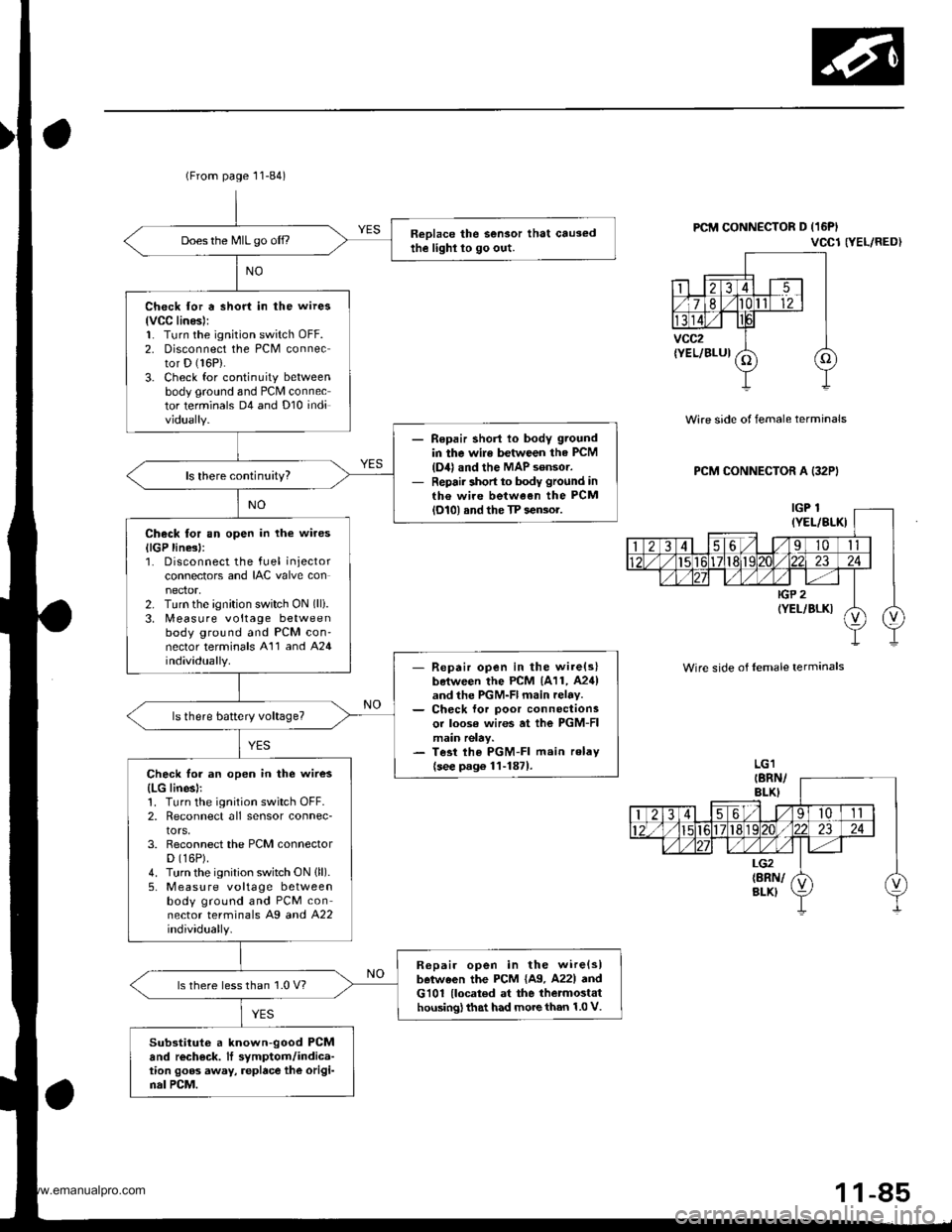
(From page 11-84)
Reolace the Sensor that causedthe lighl lo go out.Does the MIL go off.,
Check for a short in the wires
lvCC linesl:1. Turn the ignition switch oFF.2. Disconnect the PCM connector D (16P).
3. Check for continuity betweenbody ground and PCM connector terminals D4 and Dl0 individually.
Repair shorl lo body ground
in the wile between the PCM
{D4} and the MAP sensor.Repair short to body ground inth€ wire between the PCMlol0l and the TP sensor.
Check tor an open in the wires
llGP line3l:1. Disconnect the fuel injectorconnectors and IAC valve con
2. Turn the ignition switch ON (lli.
3. [,4easure voltage betweenbody ground and PCM con'nector terminals A'11 and A24individually.- Repair open in the wire(slboiween the PCM 1A11, A24)and the PGM-Fl main relav.- Ch€ck lor poor connectionsor loose wires at ihe PGM-FImain relay.- Tesi lhe PGM-FI main relav
{see p.g6 1l-1871.Check for an open in the wires
{LG linesl:1. Turn the ignition switch OFF.2, Reconnect all sensor connec-tors,3. Reconnect the PCM connectorD (16P).
4. Turn the ignition switch ON (ll).
5, M easu re voltage betweenbody ground and PCM connector terminals Ag a^d 422individually.
R6pair open in the wire{slbetween the PCM {A9. A22l andG101 {located at the thetmostathousing) that had more than 1.0 V.
ls there less than 1.0 V?
Substituto a known-good PCMand rech€ck. It symptom/indica-tion goos away, replace the origi-nal PCM.
PCM CONNECTOR D (16PI
VCCl NEL/RED}
Wire side of female terminals
PCM CONNECTOR A (32PI
Wire side of lemale terminals
1 1-85
www.emanualpro.com
Page 289 of 1395
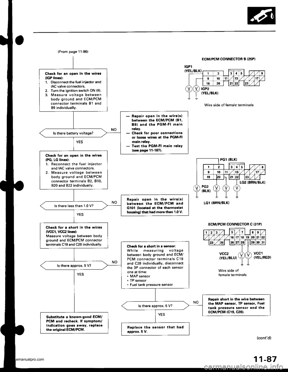
Ch€ck tor rn opon in tha wiioa(lGP lino.):1. Disconnectthe fuel inj€ctor andIAC valve connectors.2. Turn the ignition switch ON {ll}.3. Measure voltage betweenbody ground and ECM/PCMconn€ctor terminals B'l and89 individually.
- Repaii opon in th6 wirc{3lbetw.6n tho ECM/PCM (B1.
Bgl lnd tho PGM-FI mainroby.- Chock for poor connactionsor loo3€ wiJo3 at the PGM-FImain ralry.- T.st the PGM-FI mtin r.lay(soo p.ge 11-1871.
ls there battery voltage?
Chack for an opon in tho wire3
{PG, LG lino3l:1. Reconnect the luel iniectorand IAC valve connectors.2. Measure voltage betweenbody ground and ECM/PCMconnector terminals 82, 810,820 and 822 individually.
B.pair open in the wiroltlb.twocn tho ECM/PCM .ndG101 lloc.t6d rt th. thormoiathouingl that had mo.e than 1 .0 V.
lsthere lessthan 1.0 V?
Chock for a shon in the wira3
{VCCI, VCC2 lin..l:Measure voltage between bodyground and ECM/PCN4 connectorterminals C19 and C28 individuallv.Chock lor a short in r s€nsor:While measuring voltagebetwoen body ground and ECM/PCM connector terminals C19and C28 individually, disconneclthe 3P connector ol each sensorone at time:
. TP sensor. Fueltank pressure sensor
ls there approx.5 V?
Rooair ahort in tho wire b€twoentho MAP sen3or. TP sensor, Fuel
tank Dreaaure Sonsor and theECM/PCM tC19, C28).
ls there approx. 5 V?
Sub3lhuio . known-good ECM/PCM .nd rcch6ck. lf tymptom/indic.tion go.3 away, rapl.ceth. original ECM/PCM.Replece the ronsor thtt hadapprox. 5 V.
(From page 11-86)
lcont'd)
r
28
I1011't317
19202123
vXv) iiP2rELlBLK)
IGPl(YEL/BLK)
ECM/FCM CONNECTOR A {25PI
Wire side of lemale terminals
(YEL/RED)
Wire side oflemale terminals
ECM/PCM CONNECTOR C {3'IP}
| 2i37Es/'t61718 192021\22
26272elE30 31
vcc2(YEL/BLUIktvccl
11-47
www.emanualpro.com
Page 291 of 1395
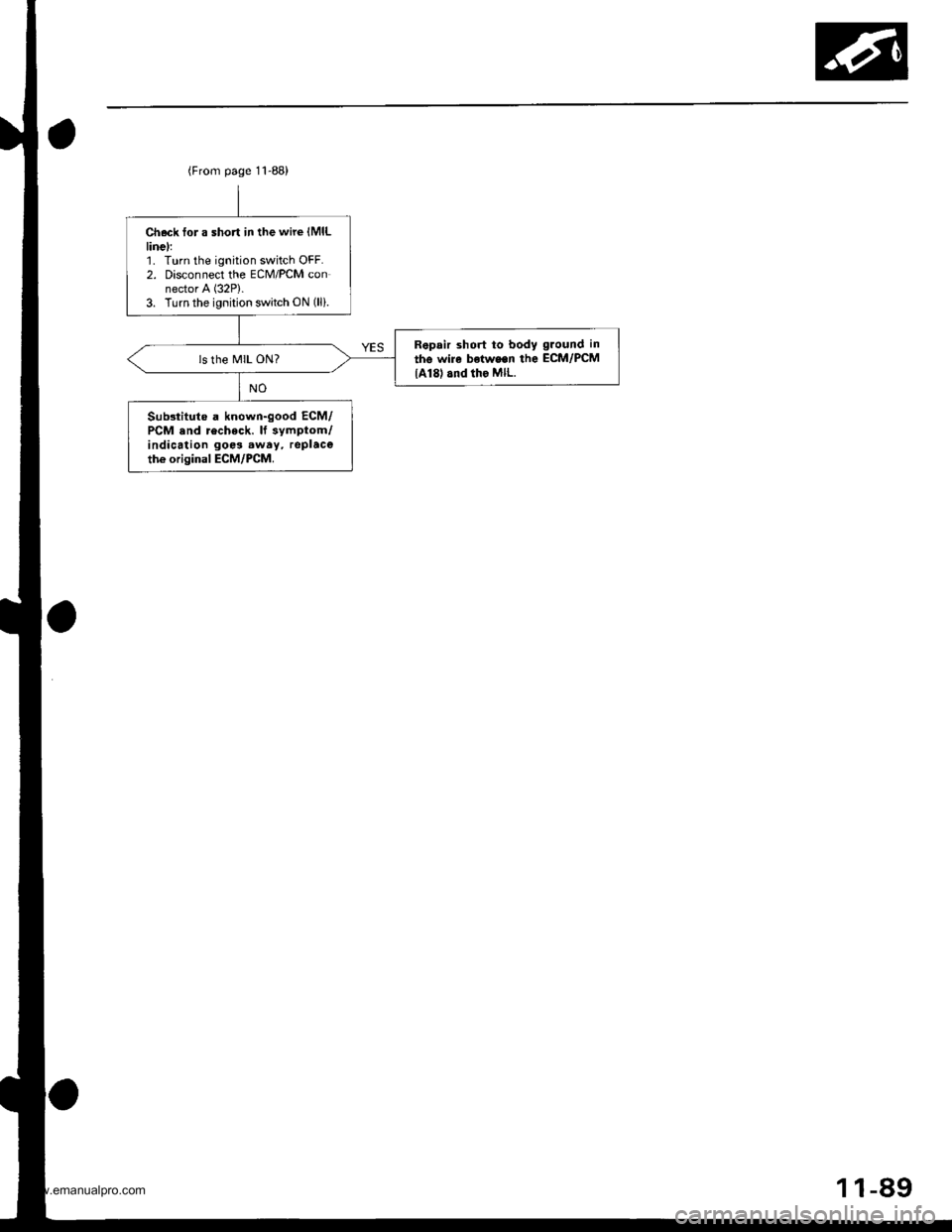
Check tor a short in the wire (MlL
linel:1. Turn the ignition switch OFF.2. Disconnect the ECM/PCM connector A (32P).
3. Turn the ignition switch ON (lli.
Repair short to body ground in
the wire b€twe.n the ECM/PCM
lA18) and tho MlL.
Substituto a known-good ECM/PCM .nd recheck. lf symptom/indication goo3 .way, replaceth€ original ECM/PCM.
(From page 11-88)
1-89
www.emanualpro.com
Page 292 of 1395
PGM-FI System
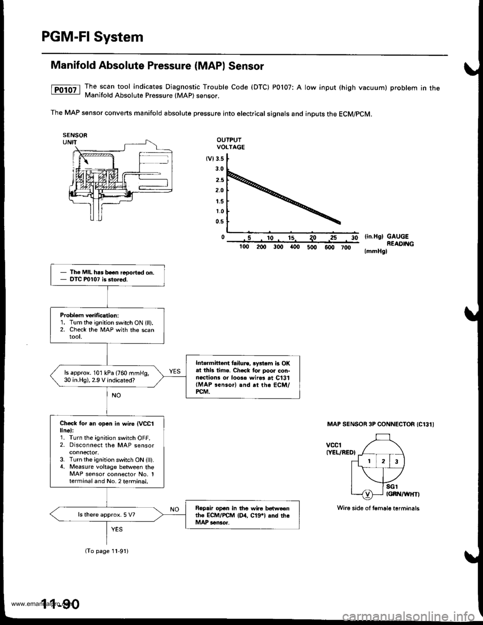
Manifold Absolute Pressure (MAPI Sensor
The scan tool indicates Diagnostic Trouble Code (DTC) POl07: A low input (high vacuum) problem in theManifold Absolute Pressure (MAP) sensor,
The MAP sensor convens manifold absolute pressure into electrical signals and inputs the ECM/pCM.
OUTPUIVOLTAGE
tvl3.s
3.0
2.5
2.O
1.5
1.0
0.5
o .5 ro- 15^ 1olin.H9) GAUGEREADIT{G
lmmHgl
3025
100 200 300 a00 5oo 6fi, 7d)
MAP SENSOR 3P CONNECTOR IC131I
vccl(YEL/RED}
Th6 MIL has b€en reoorted on.DTC P0107 is 3tored.
Problom verification:1. Turn the ignition switch ON lll).2. Check the lvlAP with the scanroot.
lrtormittem tailu.e, lystam b OKat thb timo. Check tor poor con-noctions or loosa wird at C131(MAP rensor) and rt the ECM/PCM.
ls approx. 101 kPa (760 mmHg,30 in.Hg),2.9 V indicated?
Check for an op6n in wi.o IVCC1linel:1. Turn the ignition switch OFF.2. Disconnect the MAP sensorconnector,3. Turn the ignition switch ON {ll}.4. Measure voltage between theMAP sensor connector No. 1termanal and No. 2 terminal.
Roprir op€n in the wir6 bstweentho ECM/PCM (D4, C19*l and theMAP sensor.
ls there approx. 5 V?
(To page 11-91)
11-90
Wiro side ol temale terminals
www.emanualpro.com
Page 293 of 1395
{From page 11-90)
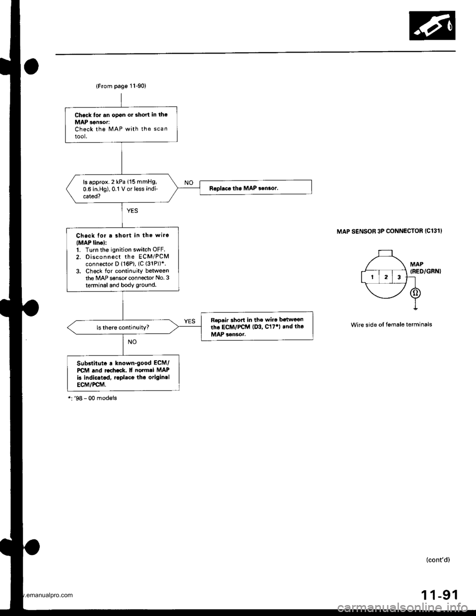
Chock tor .n open or short in the
MAP 3€n30r:Check the MAP with the scan
tool.
ls approx. 2 kPa (15 mmHg,
0.6 in.Hg),0.1 V or less indi-
cated?
Chock for a lhort in the wire(MAP linol:1. Turn the ignition switch OFF.
2. Disconnect the ECM/PCMconnector D (16P), (C 131P))*.3. Check for continuity betweenthe MAP sensor connector No.3
terminal and body ground.
R€p.ir 3hort in the wire bstwcen
tho ECM/PCM (D3, C17') rnd tho
MAP 3rnsoi.
Sub3lilut. . known-good ECM/
PCM and rocheck. lf normal MAP
k indic.tcd, r.pl.co thc originrlECM/PCM.
MAP SENSOR 3P CONNECTOR (C131I
Wire side of lgmale terminals
(cont'd)
1 1-91
www.emanualpro.com
Page 294 of 1395
![HONDA CR-V 2000 RD1-RD3 / 1.G Service Manual
PGM-FI System
Manifold Absolute Pressure (MAP) Sensor (contd)
[tn,t nn-] The scan tool indicates Diagnostic Trouble Code (DTC) P0108: A high voltage (low vacuum) problem in the|jg Manifold Absolute](/img/13/5778/w960_5778-293.png "HONDA CR-V 2000 RD1-RD3 / 1.G Service Manual
PGM-FI System
Manifold Absolute Pressure (MAP) Sensor (contd)
[tn,t nn-] The scan tool indicates Diagnostic Trouble Code (DTC) P0108: A high voltage (low vacuum) problem in the|jg Manifold Absolute")
PGM-FI System
Manifold Absolute Pressure (MAP) Sensor (cont'd)
[tn,t nn-] The scan tool indicates Diagnostic Trouble Code (DTC) P0108: A high voltage (low vacuum) problem in the|jg Manifold Absolute Pressure (MAP) sensor.
MAP SENSOR 3P CONNECTOR IC131I
Wire side of female terminals
vcclIYEL/RED}
PCM CONNECTOR D I16PI
JUMPER WIRE
sGlIGRN/WHTI
Wire side of lemale termin6ls
1
(To page 11,93)': '98 - 00 models
1-92
tcRN/wHrll IIRED/GRN|
The MIL has boen reported on.DTC m108 is slored.
Problem veritication:1. Start the engine. Hold theengine at 3,000 rpm with noload (in Park or neutral) untilthe radiator fan comes on, thenlet it idle.2. Check the MAP with the scantool.
Intermittent tailuro, system i3 OKat this time. Check tor ooor con-nections or loose wires at C131IMAP s6nsor) snd the ECM/rcM.
ls 101 kPa {760 mmHg,30 in.Hg),2.9 V or higher indicated?
Check Ior an open in the MAPsensor:1. Turn the ignition switch OFF.2. Disconnect the MAP sensor3P connector.3. lnstall a jumper wire betweenthe MAP sensor 3P connectorterminals No.3 and No.2.4. Turn the ignition switch ON {ll).5. Check the MAP with the scantool.
ls 10'l kPa (760 mmHg,30 in.Hg),2.9 V or higher indicated?
Check for an open in wire (SGlliDel:1. Remove the jumper wire.2. Measure voltage between theMAP sensor 3P connector ter-minals No. 1 and No- 2.
R6p.ir open in the wire betwoenthe ECM/PCM (D12, CTrl and theMAP sensor.
ls there approx. 5 V?
Check for an open in the wire(MAP line):1. Turn the ignition switch OFF.2. lnstall a iumper wire on thePCM connectors between D3and D12.3. Turn the ignition switch ON (ll).4. Check the MAP wirh the scantool.
Ropair opon in the wire betweenthe PCM {D3, .nd the MAP son-3('t.
ls 101 kPa 1760 mmHg, 30 in.Hg),2.9 V or higher indicated?
YES
www.emanualpro.com
Page 297 of 1395
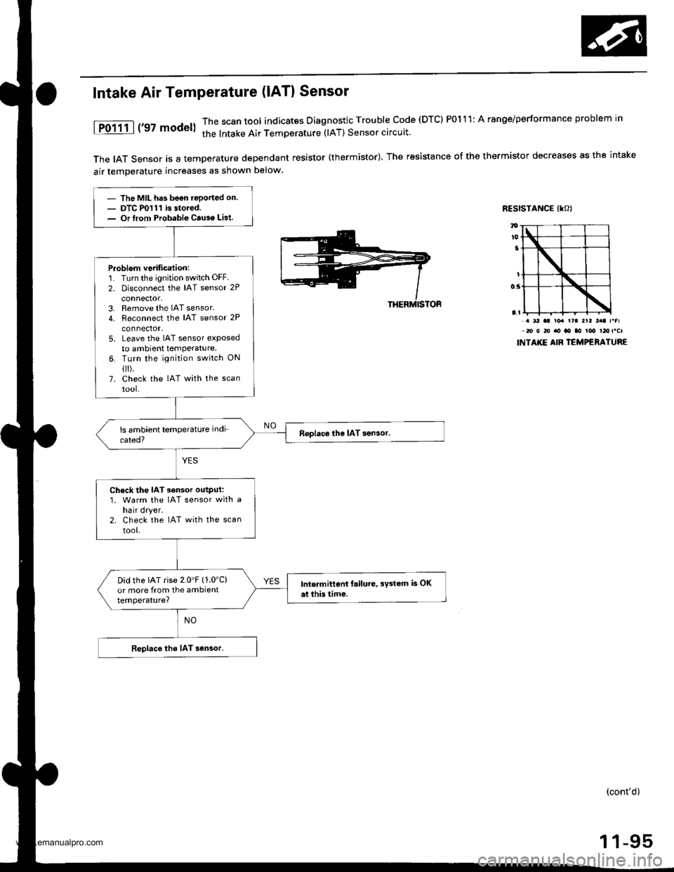
The IAT Sensor is a temperature dependant resistor (thermistor). The resistance of the thermistor decreases as the intake
air temDerature increases as shown below
RESISTANCE IKOI
Intake Air Temperature (lAT) Sensor
1P0111 | ('97 model)The scan tool indicates Diagnostic Trouble code (DTC) P0111: A ranoe/performance problem in
the lntake Air TemDerature (lAT) Sensor circuit.
. 3' aa ro. r?a arl ,.t r.fl20 0 to ao ao aa ioo t2otocl
INTAKE AIB TEMPERATURE
- The MIL has been reported on.- DTC P0111 is stored.- Or lrom Probable Cause List.
Problem vetification:1. Turn the ignition switch OFF.
2. Disconnect the IAT sensor 2P
connector,3. Remove the IAT sensor.4. Reconnect the IAT sensor 2P
connector,5. Leave the IAT sensor etposedto ambient temPerature.6. Turn the ignition switch ON
flr).7. check the IAT with the scan
tool-
R€place the IAT son3or.
Check the IAT sensor output:1. Warm the IAT sensor with ahair dryer.2. Check the IAT with the scan
tool.
Did the IAT rise 2.0'F (1.0'C)
or more from the ambienttemperature?
Intermittent f.ilure, aY3tem is OKai this tim6.
Replace the IAT sensor.
(cont'd)
1 1-95
www.emanualpro.com
Page 298 of 1395
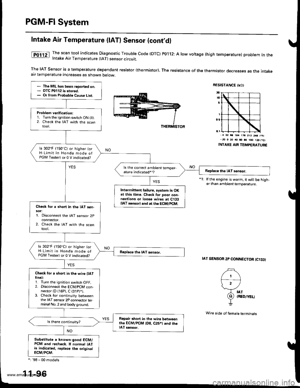
PGM-FI System
Intake Air Temperature (lAT) Sensor (cont'dl
The scan tool indicates Diagnostic Trouble code (DTC) P0112: A low voltage (high temperature) problem in theIntake Air Temperature 0AT) sensor circuit.
The IAT Sensor is a temperature dependant resistor (thermistor). The resistance of tho thermistor decreases as the intakeair temperature increases as shown below.
RESISTANCE IKO)
i')
)2 /
A tAr
9) (RED/YEU
-L
-. 32 aa rorr 1?a 2ra 2aa f.el-m 0 20 rto ao i0 too l2ofcl
INTAKE AIR TEMPERATUR€
It the engine is warm, it will b€ high-er than ambient temperature.
IAT SENSOR 2P CONNCCTOR (C'33I
- The MIL has been reDoned on.- OTC m112 is stored,- Or from Probable Caus€ List.
Problem vsrification:1. Turn the ignition switch ON flt).2. Check the IAT with the scantool.
ls 302'F (150'C) or higher (orH-Limit in Honda mode ofPGM Testeri or 0 V indicated?
ls the correct ambient temper-ature indicated,,?Beploce tho IAT sensor.
Intermittent failure, system i3 OKat this time. Ch6ck for poor con-nectiona o. loose wires rt C133{lAT s€nsorl and rt th6 ECM/pCtr4.Check for a short in the IAT sen-sot:1. Disconnect the IAT sensor 2p
2. Check the IAT with the scantool.
ls 302"F {150"C) or higher {orH-Limit in Honda mode ofPGM Tester) or 0 V indicated?Raplace the lAT aensor.
Ch€ck for a short in the wir6 llAtlinel:1. Turn the ignition switch OFF.2. Disconnect the ECM/PCM con-nector {D (16P}, C (31P)').3. Check for continuity betweenthe IAT sensor 2P connector terminalNo.2 and body ground.
Repair short in the wi.o botweenth6 ECM/rcM {D8, C25*l and th6IAT 3ensor.
Substitute a known-good ECM/PCM and recheck. lf normel IATis indicaled, replace the originalECM/PCM,
*: '98 - 00 models
1 1-96
Wi16 side of femsle terminals
www.emanualpro.com