Disc HONDA CR-V 2000 RD1-RD3 / 1.G Workshop Manual
[x] Cancel search | Manufacturer: HONDA, Model Year: 2000, Model line: CR-V, Model: HONDA CR-V 2000 RD1-RD3 / 1.GPages: 1395, PDF Size: 35.62 MB
Page 14 of 1395
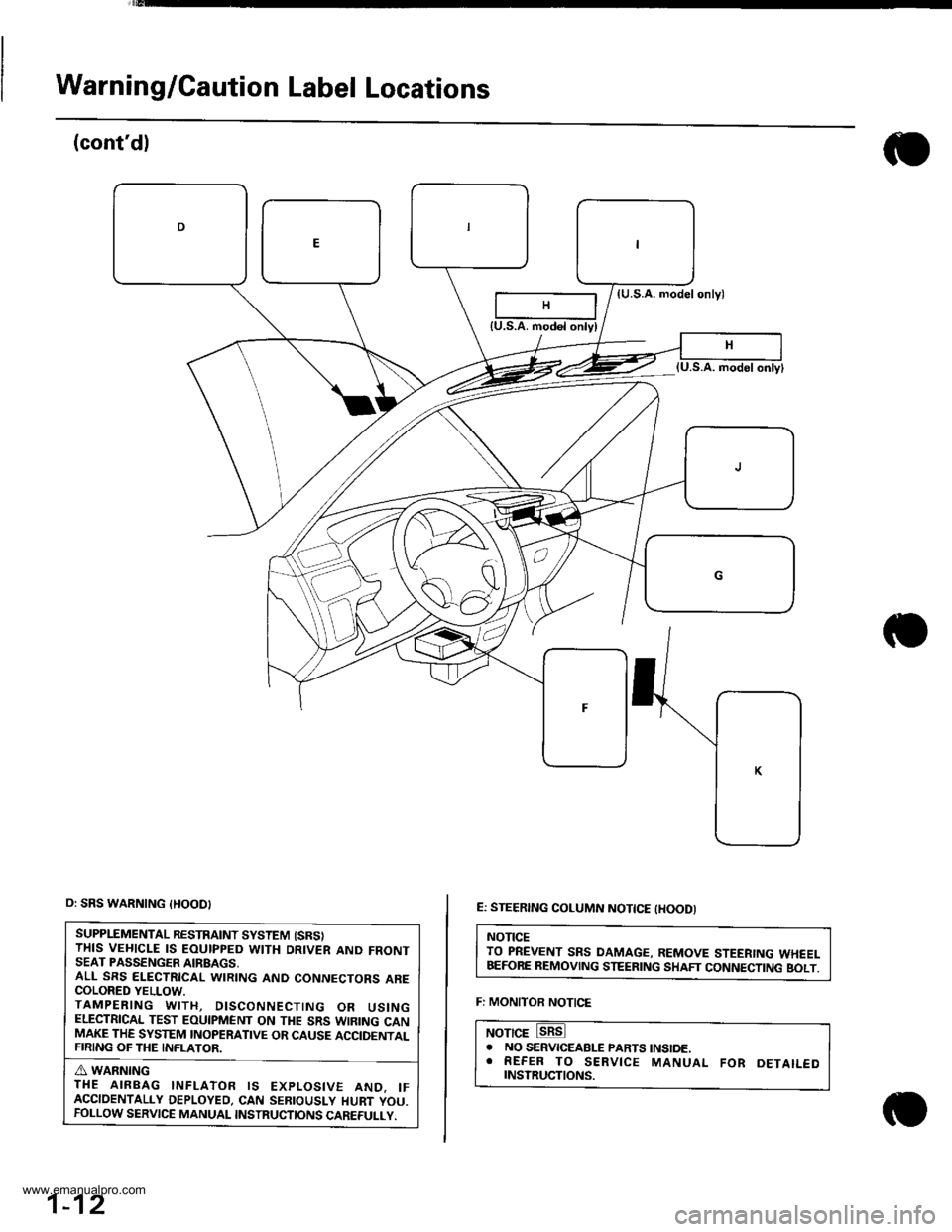
Warning/Caution Label Locations
(cont'dl
(U.S.A. modelonlyl
E: STEERING COLUMN NOTTCE tHOODI
NOTICETO PREVENT SRS DAMAGE, REMOVE STEERING WHEELBEFORE REMOVING STEERING SHAFT CONNECTING BOLT.
F: MONITOR NOTICE
NOTICE. NO SERVICEABLE PARTS tNStoE.. REFER TO SERVICE MANUAL FoR DETAILEDrNsrRucTtoNs.
{U.S.A. modol onlyl
o: SRS WARNING {HOOD}
SUPPLEMENTAL RESTRAINT SYSTEM {SRSITHIS VEHICLE IS EOUIPPED WITH DRIVER AND FRONTSEAT PASSENGER AIRBAGS,ALL SRS ELECTRICAL WIRING AND CONNECTORS ARECOLORED YELLOW.TAMPERING WITH, DISCONNECTING OR USINGELECTRICAL TEST EOUIPMENT ON THE SRS WIRING CANMAKE THE SYSTEM INOPERATIVE OR CAUSE ACCIDENTALFIRING OF THE INFLATOR.
A WARNINGTHE AIRBAG INFLATOR IS EXPLOSIVE AND. IFACCIDENTALLY DEPLOYED, CAN SEBIOUSLY HURT YOU.FOLLOW SERVICE MANUAL INSTRUCTIONS CAREFULLY.
1-12
www.emanualpro.com
Page 29 of 1395
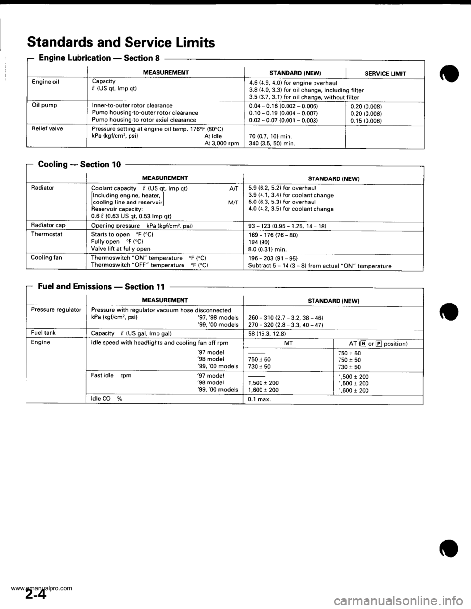
Standards andService Limits
Engine LubricationSection 8
CoolingSection 10
Fuel and EmissionsSection 11
MEASUREMENTSTANDARO {NEWISERVICE LIMIT
Engine oilCapacityf (US qt, lmp qt)4.6 (4.9, 4.0)Ior engine overhaul3.8 {4.0,3.3)for oilchange, including filter3.5 (3.7, 3.1) for oil change, without Iilter
OilpumpInner-to-outer rotor clearancePump housing-to-outer rotor clearancePump housing-to rotor axial clearance
0.04 - 0.16 (0.002 - 0.006)0.10 -0.19 (0.004 - 0.007)0.02 -0.07 (0.001 - 0.003i
0.20 (0.008)
0.20 (0.008)
0.15 (0.006)
Relief valvePressure setting at engine oil temp. 176'F (80'C)kPa (kgt/cm,, psi) At ldleAt 3,000 rpm70 (0.7, 10) min.340 {3.5,50) min.
MEASUREMENTSTANDARO INEW}
RadiatorCoolant capacity , (US q1, lmp qt)
llncluding engine, heater, ILcooling line and reservoirlReservoir capacity:0.61 (0.63 US qt,0.53lmp qt)
M/T
5.9 {6.2, 5.2}tor overhaul3.9 (4.1, 3.4ifor coolant change6.0 (6.3, 5.3ifor overhaul4.0 (4.2, 3.5) for coolant change
Radiator capOpening pressure kPa (kgf/cm?, psi)93 - 123 (0.95 - 1.25, 14 18)
ThermostatStarts to open 'F 1"C)Fully open 'F ("C)
Valve lift at tully open
169 - 176 (76 - 80)194 (90)
8.0 (0.31imin.
Cooling fanThermoswitch "ON" temperature "F {'C)Thermoswitch "OFF" temperature 'F ('C)196 - 203 (91 - 95)Subtract 5 - 14 (3 - 8) trom actual "ON" temperature
MEASUREMENTSTANDARD INEW}
Pressure regulatorPressure with regulator vacuum hose disconnectedkPa (kgflcm', psi) '97,'98 models'99, '00 rnodels260 - 31012.7 3.2,38- 46)270 -32012.8 3.3,40 - 471
FueltankCapacity / (US gal, lmp gal)58 (15.3, 12.8)
E ngineldle speed with headlights and cooling fan off rpm'97 model'98 model'99, '00 models
MTAT {E or E position)
750 r 50730 1 50
750 t 50750 r 507301 50
Fast idle rpm '97 model'98 model'99, '00 models1,5001 2001,600 r 200
1,5001 2001,5001 2001,600 r 200
ldle CO %0.1 max.
2-4
www.emanualpro.com
Page 30 of 1395
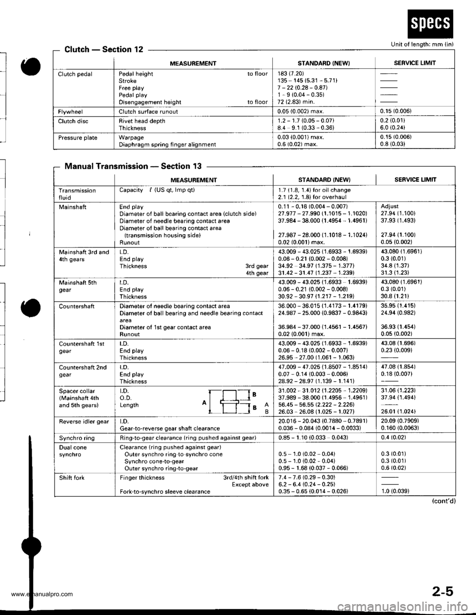
Unit of length: mm lin)ClutchSection 12
Manual TransmissionSection 13
MEASUREMENTSTANDARD INEWISERVICE LIMIT
Clutch pedalPedal height to floorStrokeFree playPedal play
Disengagement height to floor
183 (7.20)
135- 14515.31 - 5.71)7 - 2210.24 - 0.41J1-9 (0.04-0.35)
7212.83) min.
Clutch surface runout0.05 (0.002) max.0.r5 (0.006)
Clutch discRivet head depthThickness1.2 - 1.710.05- 0.07)8.4 9.1 (0.33,0.36)0.2 (0.01)
6.0 i0.24)
Pressure plateWarpageDiaphragm spring finger alignment0.03 (0.001)max.
0.6 (0.02) max.0.15 (0.006)
0.8 (0.03)
MEASUREM€NTSTANDARD INEW} I SERVICE I-IMIT
TransmissionfluidCapacity f (US qt, lmp qti1.7 11.8, 1.4)for oilchange2.1 (2.2, 1.8){or overhaul
MainshaftEnd play
Diameter of ball bearing contact area (clutch side)Diameter of needle bearing contact areaDiameter of ball bearing contact area(transmission housing side)Runout
0.'11 - 0.18 (0.004 - 0.007)27.977 - 27.990 (1.1015 - 1.1020)37.984 - 38.000 (1.4954- 1.4961)
27.987 - 28.000 (1.1018 - 1.1024)0.02 (0.0011max.
Adjust27.94 (1.100)
37.93 (1.493)
27.94 (1.100)
0.05 {0.002)
Mainshatt 3rd and4th gearsLD.End play
Thickness 3rd gear4th gear
43.009 - 43.025 1 1.6933 - 1.6939)0.06 - 0.21 (0.002 - 0.008)34.92 34.97 11.375 - 1.377)31.42 - 31.4'7 11.237 , 1.2391
43.08011.6961)0.3 (0.01)
34.811.37)31.311.23)
Mainshaft sthgearLD.End play
Thickness
43.009 - 43.02511.6933 1.6939)0.06 - 0.21 (0.002 - 0.008)30.92 - 30.97 {1.217 - 1.219)
43.08011.6961)0.3 (0.01)
30.8 (1.21)
CountershaftDiameter ol needle bearing contact areaDiameter oI ball bearing and needle bearing contact
Diameter o{ 1st gear contact areaRunout
36.000 - 36.015 {1.4173 - 1.4179)24.987 - 25.000 (0.9837 - 0.9843)
36.984 - 37.00011.4561 -1.4567)
0.02 (0.001)max.
3s.95 (1.415)
24.94 (0.982)
36.93 (1.4s4)
0.0s (0.002)
countershatt 1stgearLD.End playThickness
43.009 - 43.025 (1.6933 1.6939)0.06 - 0.18 (0.002 - 0.007i26.9s,27.00 (1.061 - 1.063)
43.08 (1.696)
0.2310.009)
Countershaft 2ndgeart.D.End playThickness
47.009 - 47.025 (1.8507 - 1.8514)0.07 - 0.14 10.003 ,0.006)
2As2 - 2a.97 l1.139-1.1411
47.08 {1.854)0.18 (0.007)
Spacer collar(Mainshaft 4thand 5th gears)
t.D.o.D.Length A'ls I
le31 .002 - 31 .O12 11 .2205 , 1 .2205)37.989 - 38.000 (1.4956 1.4961)56.45 - 56.55 Q.222 - 2.226126.03,26.08 (1.025 - 1.027)
31.06 (1.223)
37.94 (1.494)
26.01 t1 .0241
Reverse idler geart.D.Gear-to-reverse gear shaft clearance20.01 6 - 20.043 (0.7880, 0.7891)0.036 - 0.084 (0.0014 - 0.0033)20.09 (0.7909)
0.16010.0063)
Synchro ringRing-to-gear clearance (ring pushed againsl gear)0.85 - r.10 (0.033 0.043)0.4 (0.02)
Dual coneClearance (ring pushed against gear)
Outer synchro ring to synchro coneSynchro cone-to-gearOuter synchro ring-to-gear
0.5 1.0 (0.02 0.04)0.5 - 1.0 (0.02 - 0.04)0.95 - 1.68 (0.037 - 0.066)
0.3 (0.01)
0.3 (0.01)
0.6 (0.02)
Shift forkFinger thickness 3rdl4th shift lorkExcept aboveFork-to-synchro sleeve clearance
7.4 - 7.6 (0.29 - 0.30)6.2 - 6.4 (0.24- 0.2s)0.35 - 0.65 (0.0't4 - 0.026)'t, torag)
www.emanualpro.com
Page 32 of 1395
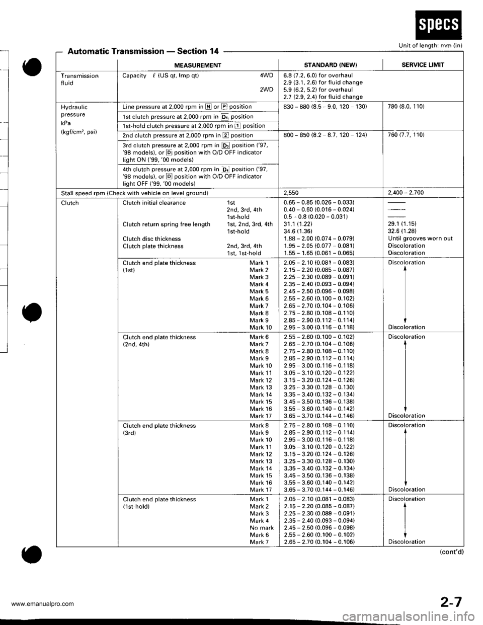
Unit of length: mm (in)Automatic TransmissionSection 14
MEASUREMENTSTANDARO INEW}SERVICE LIMIT
TransmissionfluidCapacity I {US qt, lmp q0 4WD
2WD
6.8 (7.2, 6.0) for overhaul2.9 (3.1, 2.6) for fluid change5.9 {6.2, 5.2)for overhaul2.7 {2.9, 2.4}for fluid change
Hydraulicpressure
kPa
(kgflcm', psi)
Line pressure at 2,000 rpm in LII or El position830 - 880 (8.5 - 9.0, 120 130)780 (8.0, 1't0)
1sl clutch pressure at 2,000 rpm in Da position
1st-hold clutch pressure at 2,000 rpm In l position
2nd clutch pressure at 2,000 rpm in El position800 - 850 (8.2 4.7,120 1241760 t7.7, 1101
3rd clutch pressure at 2,000 rpm in E position ('97,'98 models), or E position with O/D OFF indicatorlight ON ('99,'00 models)
4th clutch pressure at 2,000 rpm in gl position ('97,'98 models), or E position with O/D OFF indicatorlight oFF ('99,'00 models)
Stall speed rpm (Check with vehicle on level ground)2,5502,400,2,700
Clutch initial clearance 1st2nd,3rd,4th'lst-hold
Clutch return spring free length 1st, 2nd, 3rd, 4th'1st-hold
Clutch disc thicknessClutch plate thickness 2nd, 3rd, 4th1st, 1st-hold
0.65 - 0.85 (0.026 -0.033)
0.40 - 0.60 (0.016 - 0.024)0.5 - 0.8 (0.020 - 0.031)31 .1 11 .22)34.6 (1.36)
1.88 - 2.00 (0.074 - 0.079)'r.95 - 2.05 {0.077 0.081)'1.55- 1.65 (0.061 - 0.065)
29.1 (1.15)
32.6 (r.28)
Until grooves worn outDiscolorationDiscoloration
Clutch end plate thickness Mark 1(lsti Mark 2Mark 3Mark 4Mark 5Mark 6Mark 7Mark 8Mark IMark 10
2.05 - 2.r0 (0.081 - 0.083)2.15 2.20 (0.085 - 0.08712.25 2.30 (0.089,0.091)
2.35 2.40 {0.093 - 0.094}2.45 - 2.50 {0.096- 0.098}2.55 - 2.60 (0.100 - 0.102)2.65 - 2.70 (0.104 - 0.106)2.75 2.80 i0.108 - 0.110)2.85 - 2.9010.r 12 0.114)2.95 - 3.0010.116 0.118)
Discoloration
Discoloration
Clutch end plate thickness Mark 6{2nd, 4th) Mark 7Mark 8Mark 9Mark 10Mark 11lvlark 12Mark 13Mark 14Mark 15Mark 16Mark 17
2.55 2.60 10.100 - 0.102)2.65 2.70(0.104,0.106)2.75 - 2.80 (0.108 0.110)2.85 - 2.90 (0.112 -0.rr4)
2.95 3.00 (0.116-0.118)
3.05 - 3.10 (0.120 - 0.122)3.15 3.20 (0.124-0.126)
3.25 - 3.30 (0.128 0.130)3.35 - 3.40 (0. r32 - 0.134)3.45 - 3.50 (0.136 - 0.138)3.55 3.60 (0.140 - 0.142)3.65 - 3.70 (0.144 - 0.146)
Discoloration
Discoloration
Clutch end plate thickness Mark 8
{3rdi Mark IMark 10Mark 11Mark 12Mark 13Mark 14Mark 15Mark 16Mark 17
2.75 - 2.80 (0.108 0.110)2.85- 2.90 (0.112 - 0.114)2.95 - 3.00 (0.116 - 0.1'j8)3.05 3.10 (0.120 - 0.122)3.15-3.20 {0.124 0.126)3.25 - 3.30 (0.128 - 0.r30)3.35 - 3.40 (0.132 - 0.r34i3.45 - 3.50 (0.136 - 0.138)3.55 - 3.60 {0.140 - 0.142)3.65 - 3.70 {0.144 - 0.r46)
Discoloration
Discoloration
Clutch end plate thickness Mark 1(1st hold) Mark 2Mark 3
No markMark 6Mark 7
2.05 2.10 (0.081 - 0.08312.r5 2.20 (0.085 - 0.087)2.25 - 2.30 {0.089 - 0.091}2.35 - 2.40 10.093 - 0.094i2.45 - 2.50 (0.096- 0.098i2.55 - 2.60 (0.r00 - 0.102)2.65 - 2.70 (0.r04 - 0.106)
(cont'd)
2-7
www.emanualpro.com
Page 36 of 1395
to
l
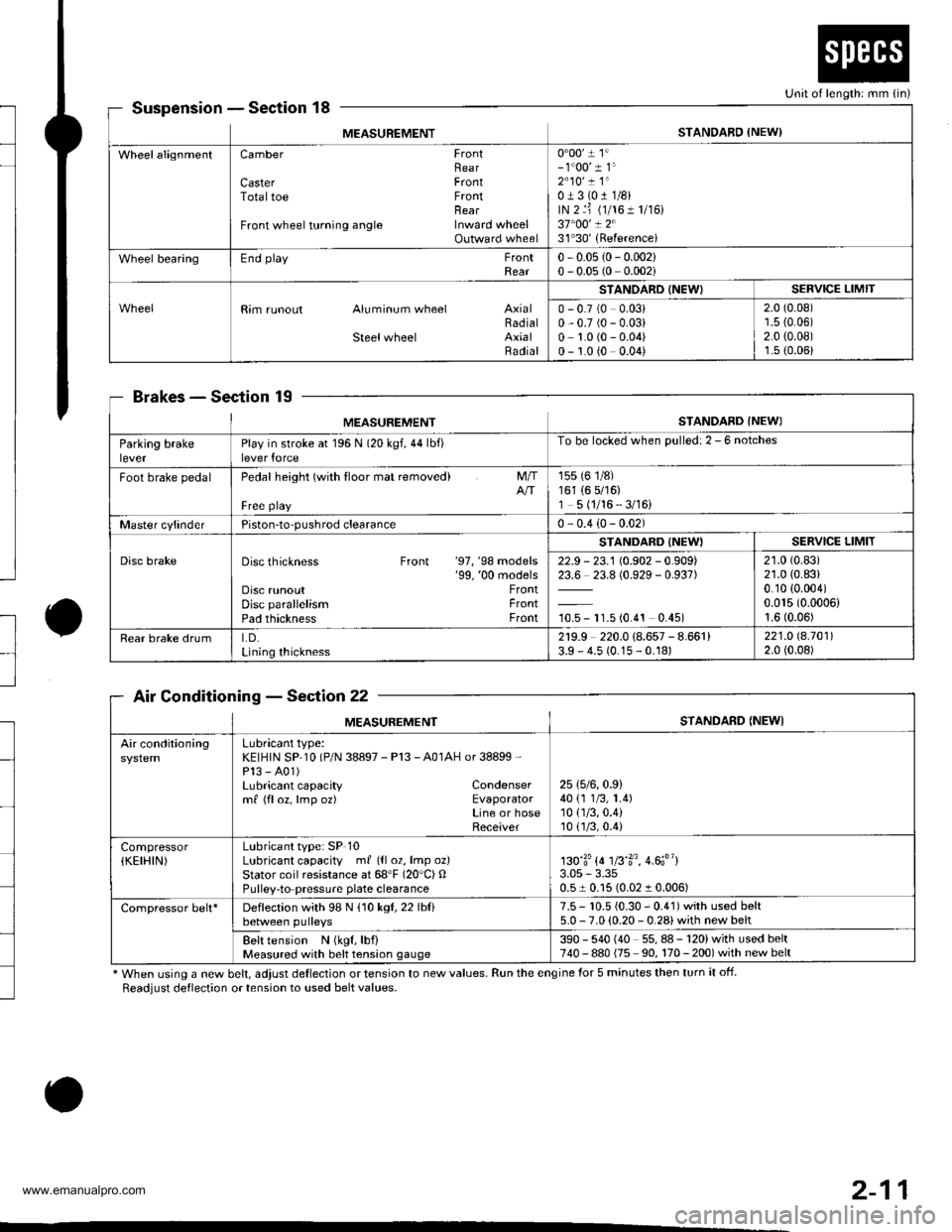
SuspensionSection 18
BrakesSec'tion 19
Air ConditioningSection 22
* When using a new belt, adjust deflection or tension to new values. Run the engine for 5 minutes then turn it off.
Readjust deflection or tension to used belt values.
o
Unit of length: mm {in)
MEASUREMENTSTANDARD {NEW)
WheelalignmentCamber FrontRearCaster FrontTotaltoe FrontnearFront wheel turning angle Inward wheelOutward wheel
0"00' 1 1'- 1"00' 1 1'2"10' ! 1"0J3(011/8)rN 2 ri (1/161 1/r6)37"00' ! 231'30'(Referencei
Wheel bearingEnd playFrontRear0 - 0.05 {0- 0.002}0 - 0.05 (0 0.002i
Rim runout Aluminum wheel AxialBadialSteelwheel AxialRadial
STANOARD (NEW)SERVICE LIMIT
0 - 0.7 (0 0.03)0,0.7 (0 - 0.03)0 1.0 (0 - 0.04)0 - 1.0 {0 - 0.04)
2.0 (0.08)'r.5 {0.06)2.0 {0.08)1.s (0.06)
MEASUREMENTSTANDARD INEWI
Parking brakeleverPlay in stroke at 196 N (20 kgf,44lbf)lever force
To be locked when Dulled: 2 - 6 notches
Foot brake pedalPedal height (with tloor mat removed)
Free playNT
155 (6 1/8)161 (6 5/16)1 5 (1/16 - 3/16)
Master cylinderPiston-to-pushrod clearance0 - 0.4 (0- 0.02)
Disc brakeDisc thickness Front '97, '98 models'99, '00 modelsDisc runoutDisc parallelismPad thickness
FrontFrontFront
STANDARD {NEW'SERVICE LIMIT
22.9 - 23.1 (0.902 - 0.909)23.6 23.8 (0.929 - 0.937)
10.5 - 11.5 (0.4't 0.45)
21.0 (0.83)
21.0 (0.83)
0.10 {0.004)0.015 (0.0006)
1.6 (0.06)
Rear brake drumLD.Lining thickness
2r9.9 220.0 (8.657 - 8.661)3.9 - 4.5 (0.15 - 0.18)221.O 8.70112.0 (0.08)
MEASUREMENTSTANDARD {NEWI
Air conditioningLubricant type:KEIHIN SP 10 (P/N 38897 - Pl3 - A01AH or 38899 -
Pl3 - A01)Lubricant capacity Condensermf {floz, lmp oz) EvaporatorLine or hoseReceiver
25 (5/6,0.9)
40 {1 1/3, 1.4)10 {1/3,0.4)10(.]/3,0.4)
Compressor(KEIHIN)Lubricant type: SP 10Lubricant capacity ml ({l 02, lmp oz}Stator coil resistance at 68'F (20"C) OPulley-to-pressuae plate clearance
130'3'{4 1fi'3o, 4.6;"}3.05 - 3.350.51 0.15 (0.02 1 0.006)
Compressor belt*Deflection with 98 N (10 kgl,22lblibetween pulleys7.5 - 10.5 {0.30 - 0.41) with used belt5.0 - 7.0 (0.20 - 0.28) with new belt
Belt tension N (kgf, lbf)Measured with belt tension gauge390 - 540 (40 55,88-120)withusedbelt740 - 880 {75 90, 170 - 200) with new belt
2-11
www.emanualpro.com
Page 38 of 1395
--
-
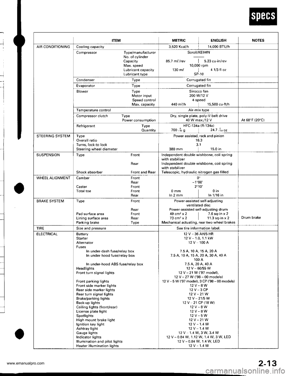
METRICITEMENGLISHNOTES
AIR CONDITIONINGCooling capacity3,520 Kcal/h j 14,000 BTU/h
Compressor Type/manutacturerNo. of cylinderCaPacityMax. speedLubricant capacityLubricant type
Scroll/KElHlN
85.7 mf/rev | 5.23 cu'in/rev10,000 rpm130mf 1 algIlozsP-10
Condenser TypeCorrugated fin
Evaporator TypeCorrugated fin
Blower TypeMotor inputSpeed controlMax. capacity
Sirocco fan200 w 112 v4-Speeo440 m3/h 15,500 cu fvh
Temperature control
Compressor clutch TypePower consumptionDry, single plate, poly-V-belt drive40 W max./12 VAt 68'F (20 C)
Befrigerant TypeOuantity
HFC-134a 1R-134a)zoo o' g 24j an oz
STEERING SYSTEMTypeOverall ratioTurns, lock to lockSteering wheel diameter
Power assisted, rack and pinion
SUSPENSIONType Front
Bear
Shock absorber Front and Rear
Independent double wishbone, coil springwith stabilizerIndependent double wishbone, coil springwith stabilizerTelescopic, hydraulic nitrogen gas tilled
WHEEL ALIGNMENTCamber
CasterTotaltoe
FronthearFrontFrontRear0inln 1/16 in0mmln2mm
0'- r"00'2.10'
BRAKE SYSTEMTvpe
Pad surface areaLining surface areaParking brake
Front
RearFrontRearTvpe
Power-assisted selt-ad,ustingventilated discPower assisted self-adiusting drum49 cm, x 2 7.6 sq-in x 273 cm, x2 11.3 sq-in x 2Mechanical actuating, rear two wheel brakes
Drum brake
TIRESize and pressureSee tire inlormation label.
ELECTRICALBafteryStarterAlternator
In under-dash fuse/relay boxIn under hood fuse/relay box
In underhood ABS fuse/relay boxHeadlightsFront turn signal lights
Front parking lightsFront side marker lightsRear side marker lightsRear turn signal lightsErake/parking lightsBack-up lightsCeiling lights {fronvrear)License plate lightSpotlightsHigh mount brake lightlgnition key lightAshtray lightGauge lightsIndicator lightslllLrmination and pilot IightsHeater illumination lights
12 V, 36 AH/s HR12V 1.0, 1.1 kW12V 100A
7.5 A, 10 A, 15 A, 20 A7.5 A, 10 A, 15 A, 20 A, 30 A, 40 A'100 A7.5 4,20 A. 40 A12V 60/55 W12 V- 21 W ('97 model),12 V - 27 W ('98-00 models)12V 5 W {'97 model),3 CP ('98 - 00 models)12V-8W12 V,3 CP12V-21W12 V 2115 W12V 21 CP (18 W)12V-8W12V-8W12V-5W12V -21W
12 V- 1.4 W12V 1.4 W12 V 1.4 W,3 W,3.4 W12V-0.84W, 1.12 W, 1.4 W,3 W, LED12 V - 0.84 W, 1.4 W, LED12 V,1.4 W
2-13
www.emanualpro.com
Page 57 of 1395
RE
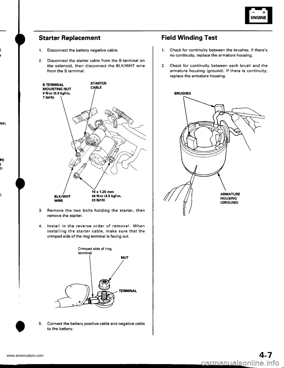
Starter Replacement
1.
B TERMINALMOUNNNG NUTI N.m (0.9 kgl.m,7 rbt ftl
Remove the two bolts holding the starter. then
remove the starter.
4. Install in the reverse order of removal. When
installing the starter cable, make sure that the
crimped side ofthe ring terminal is facing out,
Crimped side of ringterminal
TERMINAL
Connect the battery positive cable and negative cable
to the batterv.
Disconnect the battery negative cable.
Disconnect the starter cable from the B terminal on
the solenoid. then disconnect the BLK/WHT wire
from the S terminal.
STARTER
l0 x 1.25 mm4,1 N.m {4.5 kgf.m,33 tbt.ftl
5.
o
Field Winding Test
Check for continuity between the brushes. lf there's
no continuity, replace the armature housing,
Check for continuity between each brush and the
armature housing {ground). lf there is continuity.
replace the armature housing.
t.
ERUSHES
4-7
www.emanualpro.com
Page 63 of 1395
,r1.?
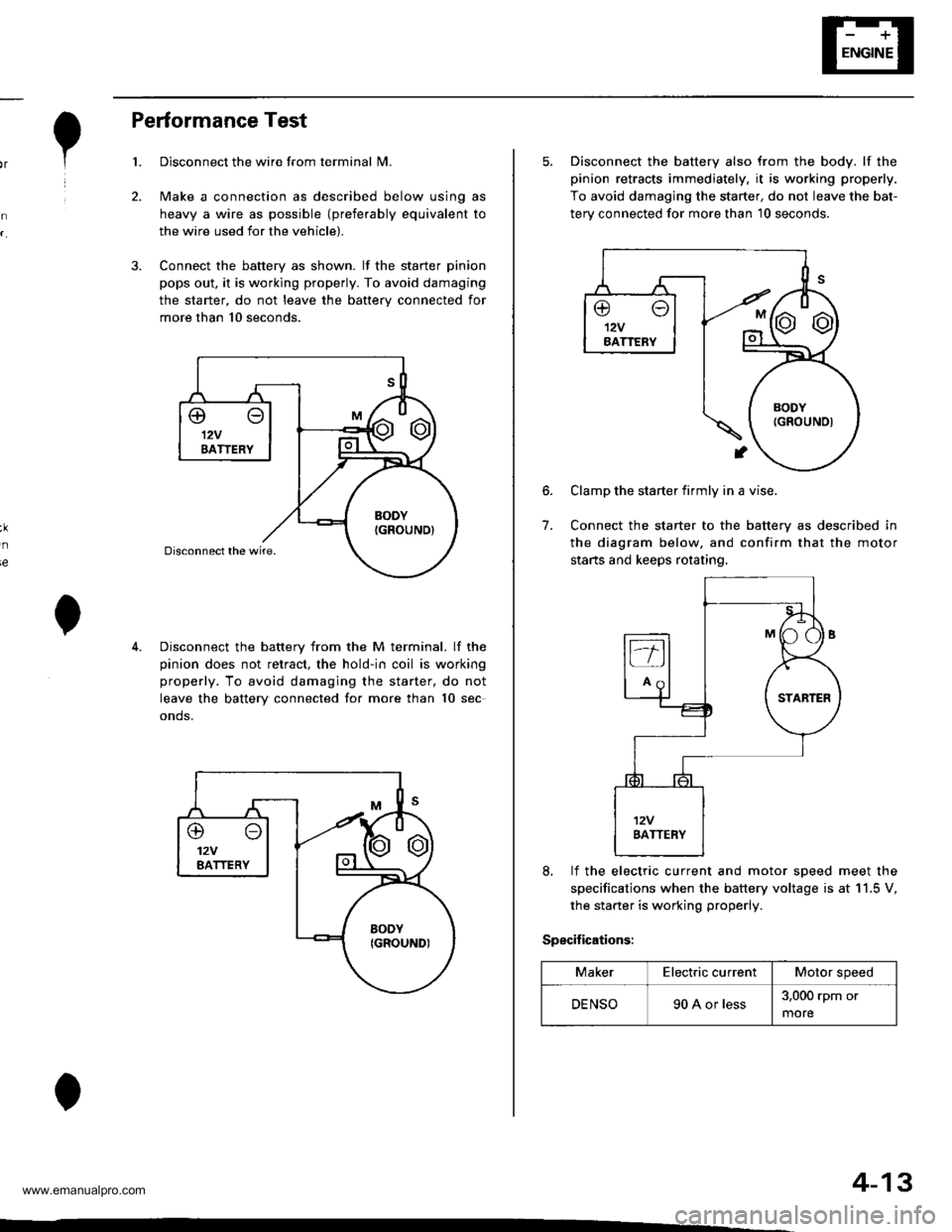
Performance Test
Disconnect the wire from terminal N4.
Make a connection as described below using as
heavy a wire as possible (preferably equivalent to
the wire used for the vehicle).
Connect the battery as shown. lf the starter pinion
pops out. it is working properly. To avoid damaging
the starter, do not leave the battery connected for
more than 10 seconds.
3.
ie
Disconnect the battery from the M terminal. lf the
pinion does not retract, the hold-in coil is working
properly. To avoid damaging the starter, do not
leave the battery connected for more than 10 sec
onds.
@o12VBATTERY
4-13
5. Disconnect the battery also from the body. lf the
pinion retracts immediately, it is working properly,
To avoid damaging the starter, do not leave the bat-
terv connected for more than 10 seconds.
6.
7.
Clamp the starter firmly in a vise.
Connect the starter to the battery as described in
the diagram below, and confirm that the motor
starts and keeps rotating.
8, lf the electric current and motor soeed meet the
specifications when the battery voltage is at 11.5 V,
the starter is working properly.
Specifications:
MakerElectric currentMotor speed
DENSO90 A or less3,000 rpm or
more
www.emanualpro.com
Page 66 of 1395
lgnition System
5.
lgnition Timing Inspection and Setting
2.
1.Check the idle speed, and adjust it if necessary (see
section 1 1).
Pull out the service check connector 2P (BRN and
BLK wires) from the connector holder located under
the dash on the front passenger side, then connect
the scs service connector (P/N 07PAz - 0010100) to
it.
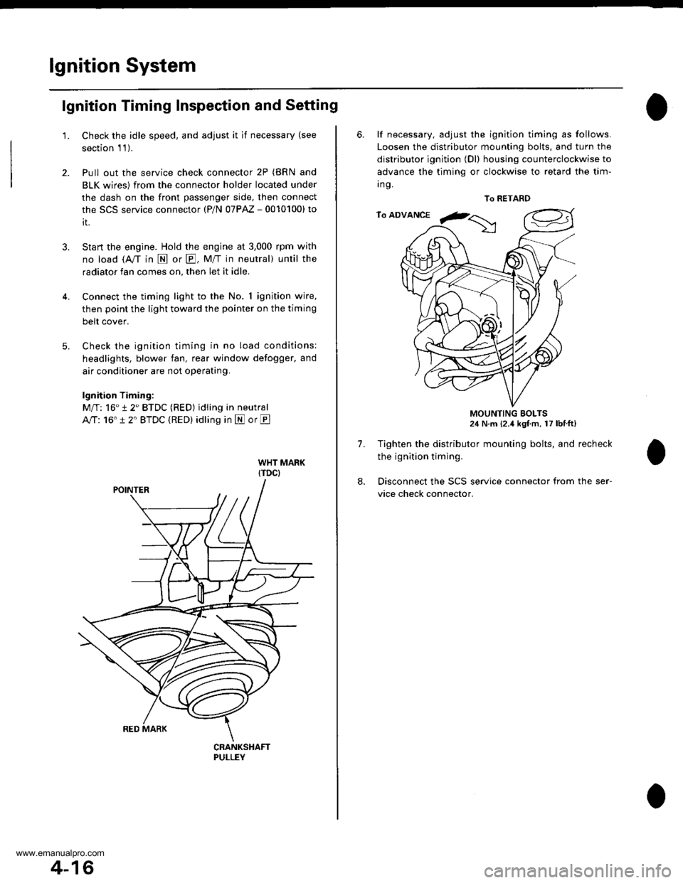
Start the engine. Hold the engine at 3,000 rpm with
no load (A/T in N or E, Mff in neutral) until the
radiator fan comes on, then let it idle.
Connect the timing light to the No. I ignition wire,
then point the light toward the pointer on the timing
belt cover.
Check the ignition timing in no load conditions:
headlights, blower fan, rear window defogger, and
air conditioner are not operating.
lgnition Timing:
M/T: 16" 12" BTDC (RED) idling in neutral
AlTt'16" !2" BTDC (RED) idling in E or E
CRANKSHAFTPULLEY
4-16
6. lf necessary, adjust the ignition timing as follows.
Loosen the distributor mounting bolts, and turn the
distributor ignition (Dl) housing counterclockwise to
advance the timing or clockwise to retard the tim-
t no,
7.
8.
MOUNTING BOLTS24 N.m {2.4 kgf m, 17 lbtft}
Tighten the distributor mounting bolts, and recheck
the ignition timing.
Disconnect the SCS service connector from the ser-
vice check connector.
To RETARD
www.emanualpro.com
Page 67 of 1395
e
o
I'
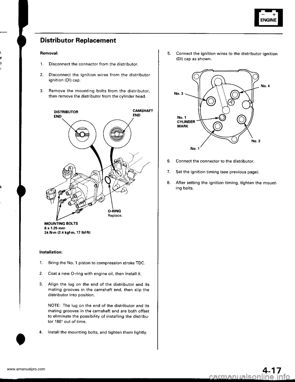
Distributor Replacement
Removal:
1. Disconnect the connector from the distributor.
2. Disconnect the ignition wires from the distributor
ignition (Dl) cap.
3. Remove the mounting bolts from the distributor,
then remove the distributor from the cylinder head.
CAMSHAFTEND
MOUNTING BOLTS8 x 1.25 mm2,1N.m {2.,1kgrf.m, 17 lbf ftl
lnstallation:
1. Bring the No. 1 piston to compression stroke TDC.
2. Coata new O-ring with engine oil, then install it.
3. Align the lug on the end of the distributor and its
mating grooves in the camshaft end, then slip the
distributor into position.
NOTE: The lug on the end of the distributor and its
mating grooves in the camshaft end are both offset
to eliminate the possibility of installing the distribu-
tor 180o out of time.
4. Installthe mounting bolts, and tighten them lightly.
5. Connect the ignition wires to the distributor ignition(Dl) cap as shown,
No. 1CYLINDERMARK
6. Connect the connector to the distributor.
7. Set the ignition timing (see previous page).
8. After setting the ignition timing, tighten the mount-
ing bolts.
4-17
www.emanualpro.com