Harness HONDA CR-V 2000 RD1-RD3 / 1.G Service Manual
[x] Cancel search | Manufacturer: HONDA, Model Year: 2000, Model line: CR-V, Model: HONDA CR-V 2000 RD1-RD3 / 1.GPages: 1395, PDF Size: 35.62 MB
Page 846 of 1395

Steering
Special Toofs ............. 17-2
Component Locations
Index ................ ....... 17-3
Troubleshooting
General Troubleshooting ................ 1 7-4
Noise and Vibration ......................... 17-8
Fluid Leaks ............. 17-10
Inspection and Adiustment
Steering Operation .......................... 17-12
Power Assist Check
With Vehicle Parked ....................
Steering Linkage and Gearbox .......
Pump Belt
Rack Guide Adjustment ...................
Fluid Rep|acement ...................,,.,....
Pump Pressure Check .................,,...
*Steering Wheel
Removal ................. 17-18
*Steering Column
Removal/lnstallation ................ ....... 17 -2O
lnspection .............. 17-21
Steering Lock Replacement ............ 17 -22
Power Steering Hoses, Lines
Ffuid Leakage Inspection ................. 17 -23
Repfacement .......... 17-23
Power Steering Pump
Repfacement .......... 17-24
Disassembly ...........17-25
fnspection .............. 17-26
Reassembly ............ 17-28
Power Steering Gearbox
Removal ................. 17-31
Disassembly ........... 17-34
Reassembly ............ 17-40
Ball Joint Boot Replacement .......... 17-50
Installation ............. 17-51
17-12
17-13
17-14
l7-15
17-15
17-16
Disassembly/Reassembly............... 17-18
4'%/b.......... -r'-7--a/
SUPPLEN\EN AL RES\RA(N SYSTES{ (SRS\
This model has an SRS which includes a driver's airbag in the steering wheel hub. a passenger's airbag in the dashboardabove the glove box ('97 - 00 models), and seat belt tensioners in the seat belt retractors ('98 - 00 models). Informationnecessary to safely service the SRS is included in this Service Manual. ltems marked with an asterisk (*) on the contentspage include, or are located near, SBS components. Servicing. disassembling or replacing these items will require specialprecautions and tools, and should only be done by an authorized Honda oearer.
To avoid rendering the SRS inoperative, which could lead to peFonal iniury or death in the event of a sevore trontalcollision. allSRS service work must be performod by an authorized Honda dealer.lmproper service procedurgs, including incorrect removal and installalion of the SRS, could lead to personal iniurycaused by unintontional deployment of th€ airbags {'97 - 00 models), and seat belt tensioners ('98 - 00 modelsl.Do not bump the SRS unit. Otherwise, the system may lail in case ot a collision, or the airbags may deploy when theignition switch is ON (lll.
SRS electrical wiring harnesses are identitied by yellow colof coding. Ralated components are located in the steeringcolumn, front console, dashboard, dashboard lower panel, and in the dashboard above the glove box. Do not use elec-trical test equipment on these cilcuits,
www.emanualpro.com
Page 866 of 1395
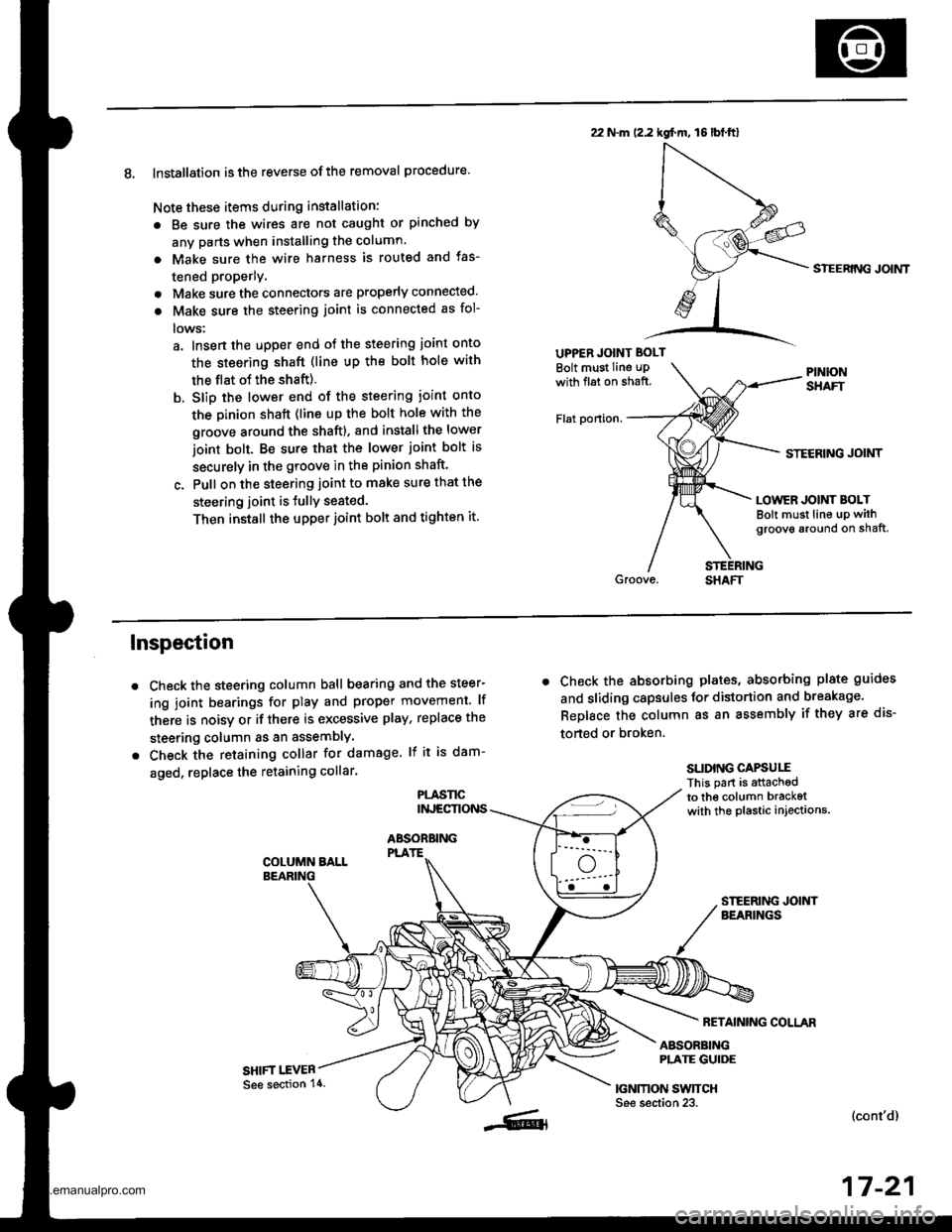
8. Installation is the reverse ofthe removal procedure.
Note these items during installation:
. Be sure the wires are not caught or pinched by
any parts when installing the column.
a Make sure the wire harness is routed and fas-
tened properly.
. Make sure the connectors are properly connected.
. Make sure the steering joint is connected as fol-
lows:
a. lnsert the uDper end of the steering joint onto
the steering shaft (line up the bolt hole with
the flat ot the shaft).
b. Slip the lower end of the steering ioint onto
the Dinion shaft (lins up the bolt hole with the
groove around the shaft). and installthe lower
ioint bolt. Be sure that the lower joint bolt is
securely in the groove in the pinion shaft'
c. Pull on the steering joint to make sure that the
steering joint is JullY seated.
Then install the upper joint bolt and tighten it.
22 N.m (2.2 kgf.m, 16lbt.ftl
UPPER JOINT BOLT
Bolt must Iine uPwith fl6t on shaft.
Flat ponion.
SIEERING JOIMT
STECRING JOINT
LOWER JOINT BOLTBolt must line up withgroove around on shaft,
Inspection
Check the steering column ball bearing and the steer-
ing joint bearings for play and proper movement. lf
there is noisy or if there is excessive play, replace the
steering column as an assemblY
Check the retaining collar for damage. lf it is dam-
aged, replace the retaining collar.
PLASl'tCINJECTIONS
ABSOBBINGPLATE
SHIFT I.EVER
. Check the absorbing plates, absorbing plate guides
and sliding capsules Jor distortion and breakage.
ReDlace the column as an assembly if they are dis-
torted or broken.
SLIDING CAPSUIIThis part is attachedto the column bracketwith the plastic injections.
FETAINING COLLAR
ABSORBINGPLATE GUIDE
|GNMON SWTTCHSee section 23.(cont'd)
17-21
See section 14.
www.emanualpro.com
Page 878 of 1395
REAR MOUNT
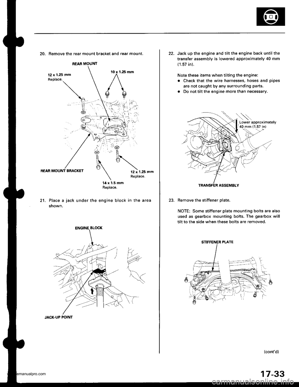
20. Remove the rear mount bracket and rear mount.
12 x 1.25 mmReplace.
REAR MOUNT BRACKET12 x 1.25 mmReplace.
21.
14 x 1.5 mmReplaco.
Place a jack under the engine block in the area
shown,
?*
JACK.UP POINT
17-33
22. Jack up the engine and tilt the engine back until the
transfer assembly is lowered approximately 40 mm
(1.57 in).
Note these items when tilting the engine:
. Check that the wire harnesses, hoses and pipes
are not caught by any surrounding parts.
. Do not tilt the engine more than necessary.
ASSEMBLY
Remove the stiffener olate.
NOTE: Some stiffener plate mounting bolts a.e also
used as gearbox mounting bolts. The gearbox will
tilt to the side when these bolts are removed.
(cont'd)
.Lower approximately'40 mm (1.57 in)
STIFFENER PLATE
www.emanualpro.com
Page 990 of 1395
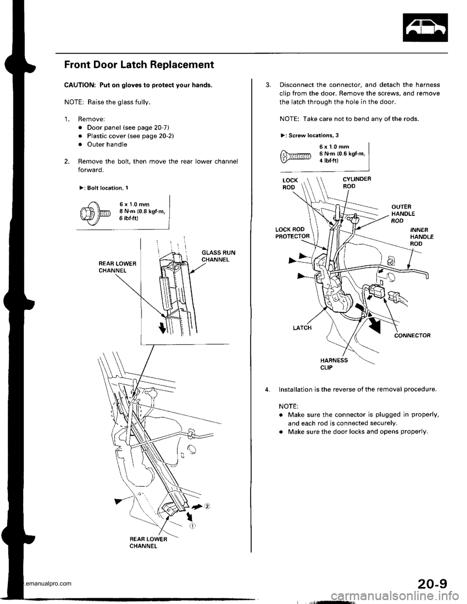
Front Door Latch Replacement
CAUTION: Put on gloves to protect your hands,
NOTEr Raise the glass fully.
'1. Remove:
. Door panel (see page 20-7)
. Plastic cover (see page 20-21
. Outer handle
2. Remove the bolt, then move the rear lower channel
forward.
>: Bolt location, 1
6xl.0mm8 N.m (0.8 kgf m,6 tbf ft)
3. Disconnect the connector, and detach the harness
clip from the door. Remove the screws, and remove
the latch through the hole in the door.
NOTE: Take care not to bend any of the rods.
>: Screw locations,3
6x1.0mm6 N.m 10.6 kgt m,4 tbf.ft)
CYLINDERROD
OUTERHANDLEROD
LOCK RODPROTECTOR
CONNECTOR
HARNESS
Installation is the reverse of the removal procedure.
NOTE:
. Make sure the connector is plugged in properly,
and each rod is connected securely.
a Make sure the door locks and opens properly.
CLIP
20-9
www.emanualpro.com
Page 991 of 1395
Doors
Front Door Glass and Regulator Replacement
CAUTION: Put on gloves to protect your hands,
1. Remove;
. Door panel (see page 20-7)
. Plastic cover (see page 20-21
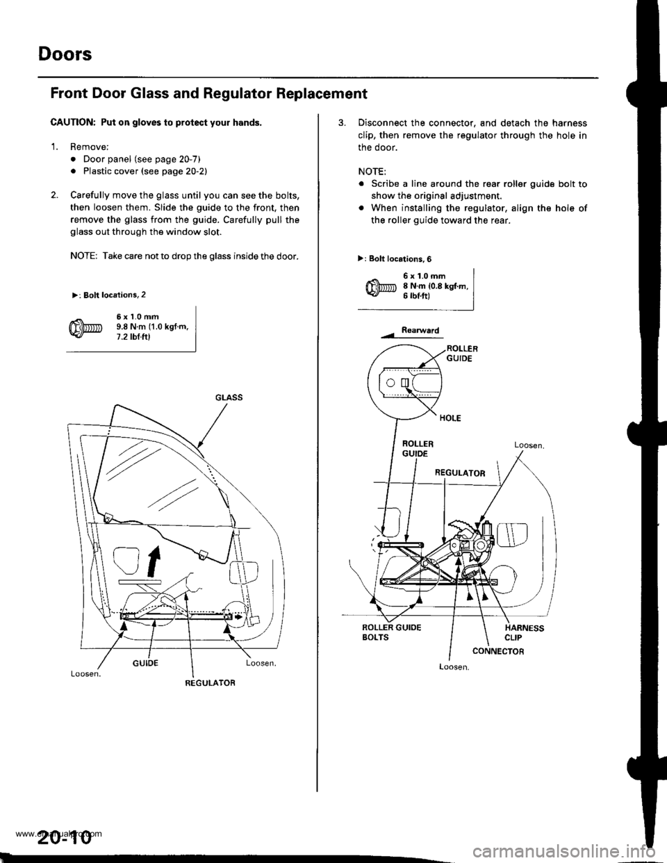
2. Carefully move the glass until you can see the bolts,
then loosen them. Slide the guide to the front, then
remove the glass from the guide. Carefully pull the
glass out through the window slot.
NOTE: Take care not to drop the glass inside the door.
>: Bolt locations,2
6xl.0mm9.8Nm(1.0kgt.m.7.2 tbt.ftl
GLASS
REGULATOR
20-10
3. Disconnect the connector, and detach the harness
clip, then remove the regulator through the hole in
the door.
NOTE:
. Scribe a line around the rear roller guide bolt to
show the original adjustment.
. When installing the regulator, align the hole of
the roller guide toward th€ rear.
>: Bolt locations,6
6x1.0mm8 N.m {0.8 kgt.m,6 rbtft)
Roaru/ard
Loosen,
www.emanualpro.com
Page 994 of 1395
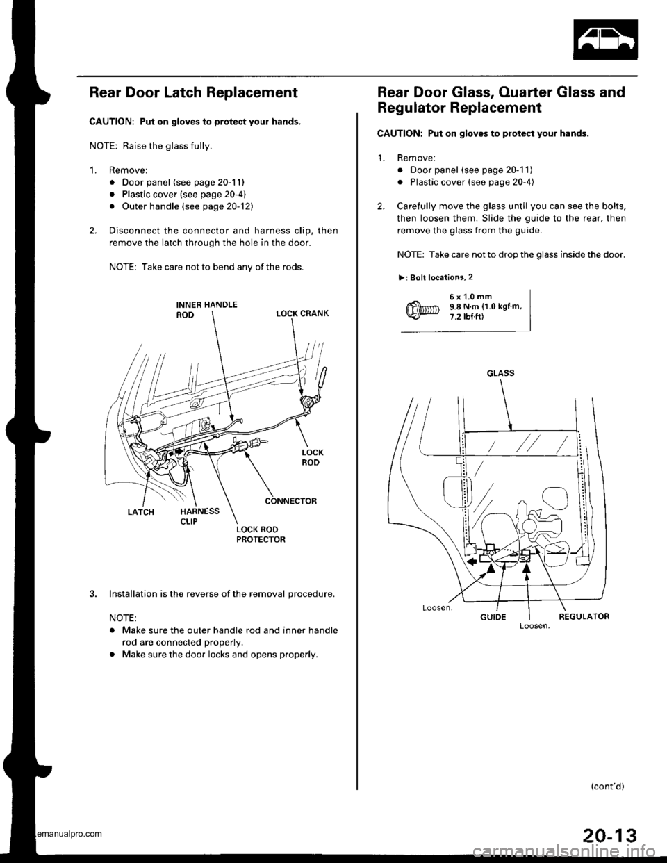
Rear Door Latch Replacement
CAUTION: Put on gloves to protect your hands,
NOTE: Raise the glass fully.
1. Removel
. Door panel (see page 20-11)
. Plastic cover (see page 20-4)
. Outer handle (see page 20-121
2. Disconnect the connector and harness clip, then
remove the latch through the hole in the door.
NOTE: Take care not to bend any of the rods.
3. Installation is the reverse of the removal procedure.
NOTE:
. Make sure the outer handle rod and inner handle
rod are connected properly.
. Make sure the door locks and opens properly.
Rear Door Glass, Ouarter Glass and
Regulator Replacement
CAUTION: Put on gloves to protect your hands.
1. Remove:
o Door panel (see page 20-1 1)
. Plastic cover (see page 20-4)
2. Carefully move the glass until you can see the bolts,
then loosen them. Slide the guide to the rear, then
remove the glass from the guide.
NOTE: Take care not to drop the glass inside the door.
>: Boll locations, 2
6x1.0mm9.8 N.m (1.0 kgtm,7.2 tb{ft)
GLASS
(cont'd)
20-13
www.emanualpro.com
Page 995 of 1395
Doors
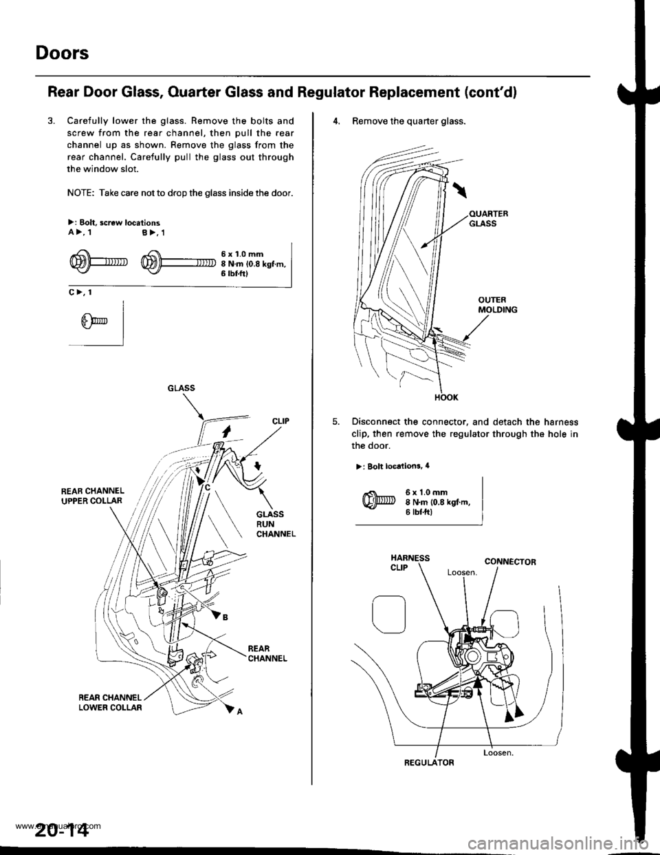
Rear Door Glass, Ouarter Glass and Regulator Replacement (cont'd)
3. Carefully lower the glass. Remove the bolts and
screw from the rear channel, then pull the rear
channel up as shown. Remove the glass from the
rear channel. Carefully pull the glass out through
the window slot.
NOTE: Take care not to drop the glass inside the door.
>: Bolt, screw locationsA>, tB>,1
-4 f 6 x 1.0 mmrTmtl-larR '^S\\\-.- -
WPU W)+ INmio.8ksf m,6 tbf.ftt
c>, 1
CLIP
20-14
''
4. Remove the quarter glass.
Disconnect the connector. and detach the harness
clip, then remove the regulator through the hole in
the door.
>: Bolt localions, 4
6x1.0mm8 N.m 10,8 kgf.m,6 tbtftl
REGULATOR
www.emanualpro.com
Page 1027 of 1395
![HONDA CR-V 2000 RD1-RD3 / 1.G Service Manual
lnterior Trim
5.
Carpet Replacement (contdl
Remove the center lower cover (M/T model).
>: Clip locations,2
lN
-ffi]
6. Remove the SRS unit covers.
>: Clip locations,2
.dL ItEu( |- qf I cARPET
FASTE HONDA CR-V 2000 RD1-RD3 / 1.G Service Manual
lnterior Trim
5.
Carpet Replacement (contdl
Remove the center lower cover (M/T model).
>: Clip locations,2
lN
-ffi]
6. Remove the SRS unit covers.
>: Clip locations,2
.dL ItEu( |- qf I cARPET
FASTE](/img/13/5778/w960_5778-1026.png)
lnterior Trim
5.
Carpet Replacement (cont'dl
Remove the center lower cover (M/T model).
>: Clip locations,2
lN'
-ffi]
6. Remove the SRS unit covers.
>: Clip locations,2
.dL ItEu( |- qf I cARPET
FASTENER('98 - 00 models)SNS UNIT
7. '97 model: Cut areas @ and @ in the carpet, then
pullthe carpet back.'98 - 00 models: Release the fastener and cut area
@ in the carpet, then pull the carpet back.
COVER
COVER
20-46
8. Remove the clips, and release the fasteners. then
remove the carpet.
NOTE: Take care not to damage, wrinkle or twist the
carpet.
>: Clip locations.3
FASTENER
lnstallation is the reverse of the removal procedure.
NOTE:
. Take care not to damage. wrinkle or twist the
carper.
. Make sure the seat harness is routed correctly.
. lf necessary, replace any damaged clips.
. Reaftach the cut areas @ and @ ('97 model) or
cut area @ ('98 - OO models) in the carpet with
wire ties.
www.emanualpro.com
Page 1034 of 1395
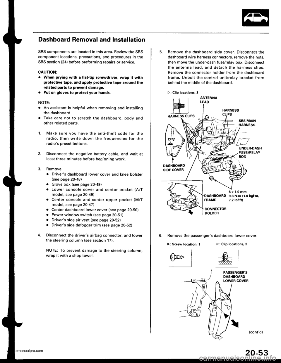
Dashboard Removal and Installation
SRS components are located in this area. Review the SRS
component locations, precautions, and procedures in the
SRS section {24) before preforming repairs or service.
CAUTION:
. When prying with a flat-tip screwdriver, wrap h withprotective tap€, and apply protective tape around the
related parts to prevgnt damage.
. Put on gloves to prot€ct your hands.
NOTE:
. An assistant is helpful when removing and installing
the dashboard.
. Take care not to scratch the dashboard, bodv and
other related parts.
1.Make sure you have the anti-theft code for the
radio, then write down the frequencies for the
radio's preset buttons.
Disconnect the negative battery cable. and wait at
least three minutes before beginning work.
Removei
a Driver's dashboard lower cover and knee bolster(see page 20-48)
. Glove box (see page 20-49)
. Lower console cover and center pocket (A/T
model, see page 20-49)
. Center console and center upper pocket (M/T
model, see page 20-47)
. Center dashboard lower cover (see page 20-50)
. Power window switch (see page 20-51)
. Driver's side air vent (see page 20-52)
. Driver's side defogger trim (see page 20-52)
Disconnect the driver's airbag connector, and lower
the steering column (see section 17)
NOTE: To prevent damage to the steering column,
wrap it with a shop towel.
2.
5. Remove the dashboard side cover. Disconnect the
dashboard wire harness connectors, remove the nuts,
then move the under-dash fuse/relay box. Disconnect
the antenna lead, and detach the harness clips.
Remove the connector holder from the dashboard
frame. Unbolt the control unit/relay bracket from
behind the middle of the dashboard.
HARNESS
6. Remove the passenger's dashboard lower cover.
D: Clip locations,
nl
-$t- Issj
I
ANTENNALEAD
>: Clip locations.
rttl
slllll
>: Scr€w location, 1
I
SF:oo I-l
SRS MAINHARNESS
UNDER.DASHFUSE/RELAYBOX
OASHBOARDSIDE COVER
6x1.0mm9.8Nm11.0kgf.m,7.2tbt.ftlDASHBOARDFFAME
CONNECTORHOLDER
PASSENGER'SDASHBOARDLOWER COVER
{cont'd)
www.emanualpro.com
Page 1035 of 1395
Dashboard
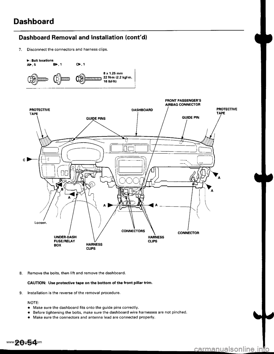
Dashboard Removal and Installation (cont'd)
7. Disconnect the connectors and harness cliDS.
>: Boli loc.lionsc>,1a>,5 B>,1
^5\h'.'_. 4fl\',r,' r$\'rmTrr' :j,1.ff,ry-r,.,".\fl)Prtu' W/* W)- tltbt.ttl
c)-
OASHBOARD
CONNECIORS
GUIDE PIN
CONNECTOR
Remove the bolts. then lift and remove the dashboard.
CAUTION: Use protective iape on the botlom of ths tront pillar trim.
lnstallation is the reverse of the removal procedure.
NOTE:
. Make sure the dashboard fits onto the guide pins correctly.
. Before tightening the bolts, make sure the dashboard wire harnesses are not pinched.
. Make sure the connectors and antenna lead are connected properly.
20-54
www.emanualpro.com