Radiator HONDA CR-V 2000 RD1-RD3 / 1.G Service Manual
[x] Cancel search | Manufacturer: HONDA, Model Year: 2000, Model line: CR-V, Model: HONDA CR-V 2000 RD1-RD3 / 1.GPages: 1395, PDF Size: 35.62 MB
Page 362 of 1395
![HONDA CR-V 2000 RD1-RD3 / 1.G Service Manual
ldle Gontrol System
Alternator (ALT) FR Signal (contdl
98 - 00 modols:
ALT CONNECTOR (C1I}5I
4P
rH] Arr FllltwHr/REo)l3laF1
I JUMPER WIRE JUMPER+ WIRE
ECM/PCM CONNECTORS
Wire side of female termi HONDA CR-V 2000 RD1-RD3 / 1.G Service Manual
ldle Gontrol System
Alternator (ALT) FR Signal (contdl
98 - 00 modols:
ALT CONNECTOR (C1I}5I
4P
rH] Arr FllltwHr/REo)l3laF1
I JUMPER WIRE JUMPER+ WIRE
ECM/PCM CONNECTORS
Wire side of female termi](/img/13/5778/w960_5778-361.png)
ldle Gontrol System
Alternator (ALT) FR Signal (cont'dl
'98 - 00 modols:
ALT CONNECTOR (C1I}5I
4P
rH] Arr Fl'l'ltwHr/REo)l3laF1
I JUMPER WIRE JUMPER+ WIRE
ECM/PCM CONNECTORS
Wire side of female terminals
ECM/PCM CONNECTOR C {31PI
Wire side of female terminals
Wire side of female terminals
ECM/PCM CONNECTOR C {31P}
": Canada
1 1-160
B (25P)
Insp€ction of ALT FR Signsl.
Check fo. a shon in th. wire {ALTF linel:1. Disconn6ct the 4P (3P)* con-nector from the ALT.2. Turn the ignition switch ON {ll).3. Measure voltage between ECM/PCM connector terminals C5and 820.Ch€ck for a sho.t in iho wirc lAlTF lino):1. Turn the ignition switch OFF.2. Disconnecl the negative bat,tery cable from the battery.3. Disconnect ECM,PCM connec-torC (31P).
4. Check for continuity betwoenbody ground and ECM/PCMconnector terminal c5.
ls there approx. 5 V7
Check the opcration of the ALT:1. Turn the ignitioo switch OFF.2. Reconnect rhe ALT 4P (3P)*connector to the ALT.3. Start the engine. Hold theengine at 3,000 rpm with noload (in Park or neutral) untilthe radiator lan comes on,then let it idle.4. Measure voltage between ECM/PCM connector terminals C5and 820.
Roprir lhort in tho wirc bstweentho ECM/PCM {Csl and the ALT.
Substitut. r known-good ECM/PCM and roch.ck. It Droscrib.dvoltage b now lvrilabls, .eplaccth. o.igin!l ECM/PCM.
Does the voltage decrease whenheadlights and rear defogger areturned on?ALT FR 3ignol is OK,
Chock lor an opon in tha wire (ALTF linel:1. Turn the ignition switch OFF.2. Disconnect the negative bat-tery cable from the battery.3. Disconnect ECM/PCM con-nector C (31P).4. Disconnect the 4P 13P)* con,nector from the ALT.5. Connect the ALT 4P {3P)* con-nector terminal No. 4 1No. 1)*to body ground with a jumper
6. Check for continuity betwe€nbody ground and ECM/PCMconnector terminal C5.
Rsprir opan wiro batw.en thoECM/PCM lcsl .nd th. ALT.ls there continuity?
AI.T F IWHT/REDI
ALT F {WHT/REDI
Wire side ot Iemale terminals
www.emanualpro.com
Page 370 of 1395
ldle Control System
Fast ldle Thermo Valve lA/T)
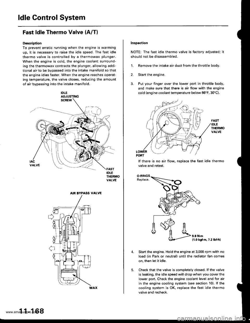
Description
To prevent erratic running when the engine is warming
up, it is necessary to raise the idle speed. The fast idle
thermo valve is controlled by a thermowax plunger.
When the engine is cold, the engine coolant surround-
ing the thermowax contracts the plunger, allowing addi-
tional air to be bvDassed into the intake manifold so that
the engine idles faster. When the engine reaches operat-
ing temperature. the valve closes, reducing the amount
of air bypassing into the intake manifold.
IDLEADJUSTING
IDLETHERMOVALVE
AIR BYPASS VALVE
11-168
Inspgction
NOTE: The fast idle thermo valve is factory adjusted; it
should not be disassembled.
1. Remove the intake air duct from the throttle body.
2. Start the engine,
3. Put your finger over the lower port in throttle body,
and make sure that there is air flow with the engine
cold (engine coolant temperature below 86"F, 30'C).
lf there is no air flow, replace the fast idle thermo
valve and retest,
O-RINGSReplace.
11.0 kgfl.m, 7.2 lbl.ftl
Start the engine. Hold the engine at 3,000 rpm with no
load (in Park or neutral) until the radiator fan comes
on, then let it idle.
Check that the valve is completely closed. lf the valve
is leaking, the idle speed will drop when you cover the
lower pon. Check the engine coolant level and for air
in the engine cooling system {see section 10). lf the
cooling system is OK, replace the fast idle thermo
valve and recheck.
www.emanualpro.com
Page 371 of 1395
ldle Speed Setting
Inspoction/Adiustmont
37 modsl:
NOTE:
. Before setting the idle speed, check the following
items:- The MIL has not been reportsd on.- lgnition timing- Spark plugs
- Air cleaner- PCV system
. lcanada) Pull the parking brake lever up. Stan the
engine, then check that the headlights are off.
1. Start the engine. Hold the engine at 3,000 rpm with
no load (in Park or neutral) until the radiator fan
comes on, then let it idle.
Connect a tachometer or a Honda PGM Tester.
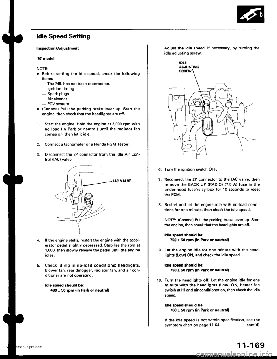
Disconnect the 2P connector from the ldle Air Con-
trol (lAC) valve.
IAC VALVE
lf the engine stalls, restart the engine with the accel-
erator pedal slightly depr6ss6d, Stabilize the rpm at
1,000, then slowly release the pedal until the engine
idles.
Check idling in no-load conditions: hsadlights,
blower fan, rear d€fogger, radiator fan, and air con-
ditioner are not operating.
ldle spood should b.:
{80 t 50 rpm {in Park or noutr.ll
IDLE
7.
Adjust the idle sp6ed,
idle adjusting screw.
if necessary, by turning the
Turn the ignition switch OFF.
Reconnect the 2P connector to the IAC valve, then
remove the BACK UP (RAD|Ol (7.5 Al fuse in the
under-hood fuse/rslav box for 10 seconds to reset
the PCM.
Restart and let the engine idle with no-load condi-
tions for one minute, then check the idle speed.
NOTE: (Canadal Pullthe parking brake lever up. Stan
the engine, then check that the headlights are off.
ldlo Ep€ed rhould be:
75O t 50 rpm (in P.rk or noutr.ll
Let the engine idl6 for one minute with the head-
lights (Low) ON, and check th€ idl€ speed.
ldle lpcod 3hould bo:
750 t 50 ]pm (in Park or nautlal)
Turn the headlights off. Let th€ engine idle for one
minute with the headlights (Low) ON, heater fan
switch at Hl and air conditioner on. then check the idle
sDeeo.
ldl. specd should b6:
7d) 1 50 rpm {in Park or nautral}
lf the idle speed is not within specification, see the
symptom chart on page 11-64. (cont'd)
1 1-169
www.emanualpro.com
Page 372 of 1395

ldle Control System
ldle Speed Setting (cont'd)
38 - 0O mod6l3:
NOTE: Before setting the idle speed, check the follow-
ing items:- The MIL has not been reported on.- lgnition timing- Spark plugs
- Air cleaner- PCV system
1. Start the engine. Hold the engine at 3.000 rpm with
no load (in Park or neutral) until the radiator fan
comes on, then let it idle.
Connect a tachometer.
Disconnect the IAC valve 2P connector and the EVAP
purge control solenoid valve 2P connector.
CONTROLSOLENOID VALVE
SOLENOID VALVE
lf the engine stalls, restart the engine with the accel-
erato. pedal slightly depressed. Stabilize the rpm at
1,000, then slowly release the pedal until the engine
idles.
Che€k the idle in no-load conditions: headlights, blow-
er fan, rear defogger, radiator fan, and air conditioner
are not operating,
ldle speed should bo:
480 t 50 rpm {in PErk or noutrall
11-170
lf necessary, adjust the idle speed, by turning the
idle adjusting screw.
After adjusting the idle speed, recheck the ignition
timing (see section 4). lf it is out of spec, go back to
steo 4.tDt.E
6. Turn the ignition switch OFF.
7. Reconnect the 2P connectors to the IAC valve and
the EVAP purge control solenoid valve, then do the
ECM/PCM reset procedure.
8. Restart and idle the engine with no-load conditions
for one minute, then check the idle speed.
ldle speod should be:,98 model:
750 t 50 rpm tin Park or neutral)'9!l - 00 modsls:
730 i 50 lpm lin Psrk or neutral)
NOTE: lf the idle speed increases to 780 t 50 rpm(770 1 50 rpml*, this means the EVAP system is
purging the canister. To stop the purging temporari-
ly, raise the engine speed above 1,000 rpm with the
accelerator pedal, then slowly release the pedal.*: '99 - 00 models
9. Let the engine idle for one minute with the head-
lights (Low) ON, and check the idle speed.
ldle speed should be:
38 mod6l:
750 f 50 rpm (in Palk or neutrall'99 - 00 modols:
730 t 50 rpm (in Palk or neutral)
10. Turn the headlights off. Let the engine idle for one
minute with the heater fan switch at Hl and air con-
ditioner on, then check the idle speed.
ldls spqed should be:'98 model:
780 t 50 rpm (in Park or neutrall'99 - 00 mod€ls:
7701 50 rpm lin Park or neutral)
lf the idle speed is not within specification. see the
Symptom Chart on page 11-64.
ADJUSTING
www.emanualpro.com
Page 396 of 1395
Intake Air System
Air Cleaner
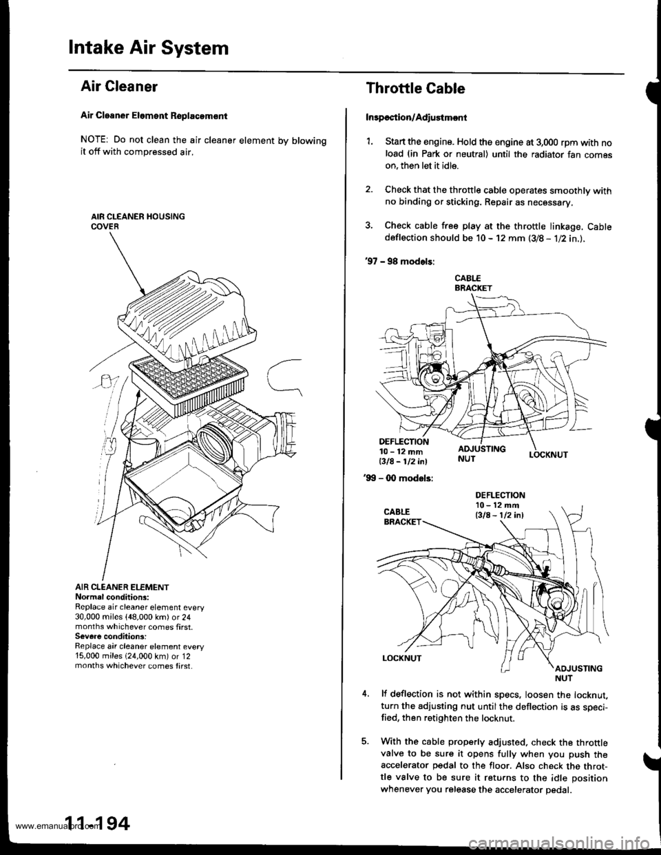
Air Cleaner Eloment Rsplacomsnt
NOTE: Do not clean the air cleaner element by blowingit off with compressed air,
AIR CLEANER ELEMENTNo.mal conditions:Replace air cleaner element every30,000 miles {48,000 km) or 24months whichever comes first.Severe condition3:Replace air cleaner element every15,000 miles 124,000 km) or 12months whichever comes tirst.
m
11-194
Throttle Cable
Inrpection/Adiustmcnt
1. Stan the engine. Hold the engine at 3,000 rpm with noload (in Park or neutral) until the radiator fan comeson, then let it idle.
2. Check that the throttle cable operates smoothly withno binding or sticking. Repair as necessary,
3. Check cable free play at the throttle linkage. Cabtedeflection should be 10- 12 mm (3/8 - 1l2in.l.
'97 - 98 modols:
CABLEBRACKET
LOCKNUT
DEFLECTION10-12mmBIA- 112 i^l
'99 - 0O modsls:
lf deflection is not within specs, loosen the locknut,turn the adjusting nut untilthe deflection is as speci-fied, then retighten the locknut.
With the cable properly adjusted. check the throttlevalve to be sure it opens fully when you push theaccelerator pedal to the floor. Also check the throt-tle valve to be sure it returns to the idle position
whenever you release the accelerator pedal.
DEFLECTIONl0-12mft
Bla - 112 inl
NUT
www.emanualpro.com
Page 397 of 1395
lnstellation
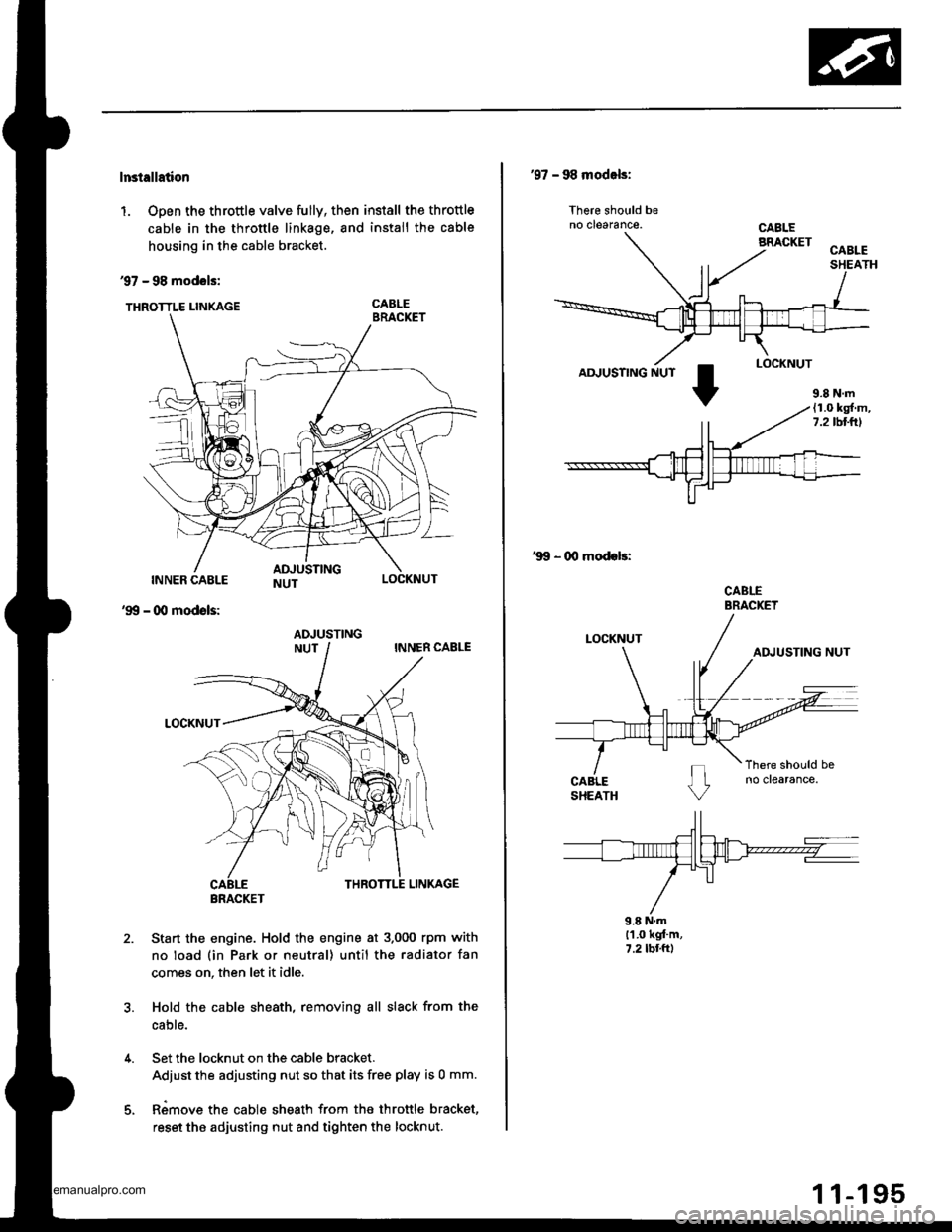
1. Open the throttle valve fully, then install the throttle
cable in the throttle linkage, and install the cable
housing in the cable bracket.
97 - 98 modols:
THRoTTLE LINKAGE CABLE
INNER CABLE
- (Xl modols:
LOCKNUT
'99
2.Sta.t the engine. Hold the engine at 3.000 rpm with
no load (in Park or neutral) until the radiator fan
comes on, then let it idle.
Hold the cable sheath, removing all slack from the
cable.
Set the locknut on the cable bracket.
Adiust the adjusting nut so that its free play is 0 mm.
Rimove the cable sheath from the throttle bracket,
reset the adjusting nut and tighten the locknut.
ADJUSTING
BRACKET
'97 - 98 modals:
lhere should beno clearance.
AD.'USTING NUT
'99 - 00 modeb:
CABLEBRACKET
9.8 N.ml'1.0 kgt'm,7.2 tbr.ft)
9.8 N.m(1.0 kg{.m,7.2lbllrl
www.emanualpro.com
Page 401 of 1395
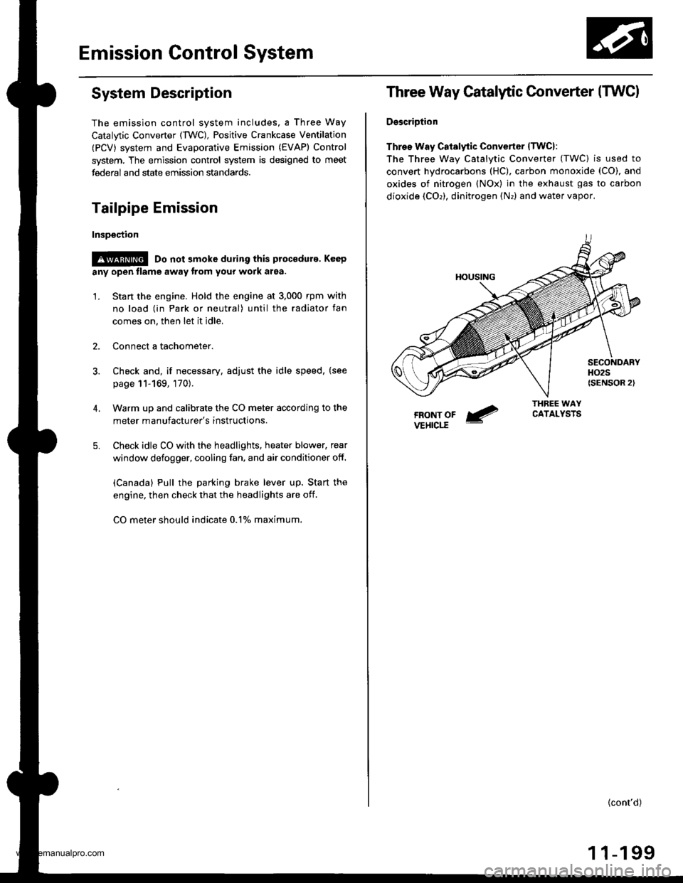
Emission Control System
System Description
The emission control system includes, a Three Way
Catalytic Converter {TWC), Positive Crankcase Ventilation
(PCV) svstem and Evaporative Emission (€VAP) Control
system. The emission control system is designed to meet
federal and state emission standards.
Tailpipe Emission
Inspsction
!@ Do not smoke during this procsdura. Keep
any open tlame away from your work area.
1. Start the engine. Hold the engine at 3,000 rpm with
no load (in Park or neutral) until the radiator fan
comes on, then let it idle,
Connect a tachometer.
Check and, if necessary, adjust the idle speed, (see
page 11-169, 170).
Warm up and calibrate the CO meter according to the
meter manufacturer's instructions.
Check idle CO with the headlights, heater blower, rear
window defogger, cooling fan, and air conditioner off.
(Canada) Pull the parking brake lever up. Start the
engine, then check that the headlights are off.
CO meter should indicate 0.1% maximum.
4.
Three Way Catalytic Converter (TWCI
DsscriDtion
Three Way Catalytic Convertsr lTwcl:
The Three wav Catalvtic Converter (TWC) is used to
convert hydrocarbons (HC), carbon monoxide (CO), and
oxides of nitrogen (NOx) in the exhaust gas to carbon
dioxide (COr), dinitrogen (Nr) and water vapor,
{cont'd)
1 1-199
www.emanualpro.com
Page 402 of 1395
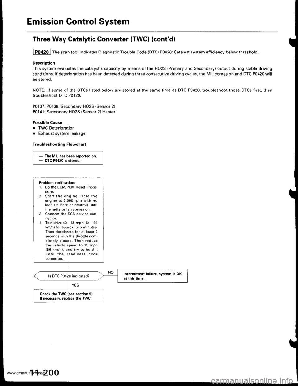
Emission Control System
Three Way Catalytic Converter {TWCI (cont'd}
1P0420 Thescantool indicates Diagnostic Trouble Code (DTC) P0420: Catalyst system efficiency belowthreshold.
DescriDtion
This system evaluates the catalyst's capacity by means of the HO2S (Primary and Secondary) output during stable driving
conditions. lf deterioration has been detected during three consecutive driving cycles, the MIL comes on and DTC P0420 will
be stored.
NOTE: lf some of the DTCS listed below are stored at the same time as DTC P0420, troubleshoot those DTCS first. then
troubleshoot DTC P0420.
P0137, P0138: Secondary HO2S (Sensor 2)
P0141: Secondary HO2S (Sensor 2) Heater
Possible Cause
. IWC Deterioration
. Exhaust system leakage
Troubleshooting Flowchart
- The MIL has been reDoried on.- DTC P0420 is stored.
Problem verification:1. Do the ECM/PCM Reset Procedure,2. Start the engine. Hold theengine at 3,000 rpm with noload (in Park or neutrali untilthe radiator fan comes on.3. Connect the SCS service connector.4. Test-drive 40 - 55 mph (64 - 88km/h) for approx. lwo minutes.Then decelerate for at least 3seconds with the throftle completely closed. Then reducethe vehicle speed to 35 mph
156 km/h), and try to hold ituntil the readiness code
Intermittent tailure. system is OKat this time.ls DTC P0420 indicated?
Check the TWC (see section 9).lI nocessary, replace the TwC.
11-200
www.emanualpro.com
Page 407 of 1395

'97 model:
The scan tool indicates Diagnostic Trouble Code (DTC) P0441: Evaporative Emission (EVAP) control system
insufficient purge flow.
Description
By monitoring the purge line vacuum with the MAP sensor, the PCM can detect insufficient EVAP control system purge
flow.
Possiblo Cause
. EVAP Purge Control Solenoid Valve
. EVAP Purge Control Solenoid Valve Circuit
. EVAP Control Canister
. Vacuum Lines
. PCM
Troubleshooting Flowchart
EVAP PURGE CONTROL
SO1TNOID VALVE 2P
CoNNECTOR (C108)
(v)
YL
Wire side of female
termrnals
(cont'd)
11-205
Th€ MIL has b€en reooited on.DTC P0441 is .tored.
Problem verificationl1. Start the engine. Hold theengine at 3,000 rpm with noload (in Park or neut.al) untilthe radiator fan comes on.2. Do the PCM Reset Procedure.3. Connect the SCS service con-nector,4. Test drive under following con'ditions on the road.- without any electrical load- Transmission in @ or @position- Engine speed between1 ,2OO - 2,4OO rpfi.- Decelerate from 50 mph (80
km/h)to 15 mph (24 km/h)Intermittent trilure, sydern is OKat this time. Check for Door con-nections or loose wir€3 at C108
IEVAP purge control solonoidvalvol .nd at the PCM.
ls DTC P0441 indicated?
Check tor an open in the wire (lcl
linel:1. Turn the ignition switch OFF.2. Disconnect the EVAP purge
control solenoid valve 2P con-nector.3. Turn the ignition switch ON (ll).
4. Measure voltage between bodyground and the EVAP purge
control solenoid valve 2P con-nector terminal No. '1,
R€pafu open in thc wir6 b€tw€enthG EVAP purge control solenoidvalve and the No. 15 ALTEBNA-TOR SP SENSOR (7.5 A)fuse.
ls there batlery voltage?
(To page 11'206)
www.emanualpro.com
Page 445 of 1395
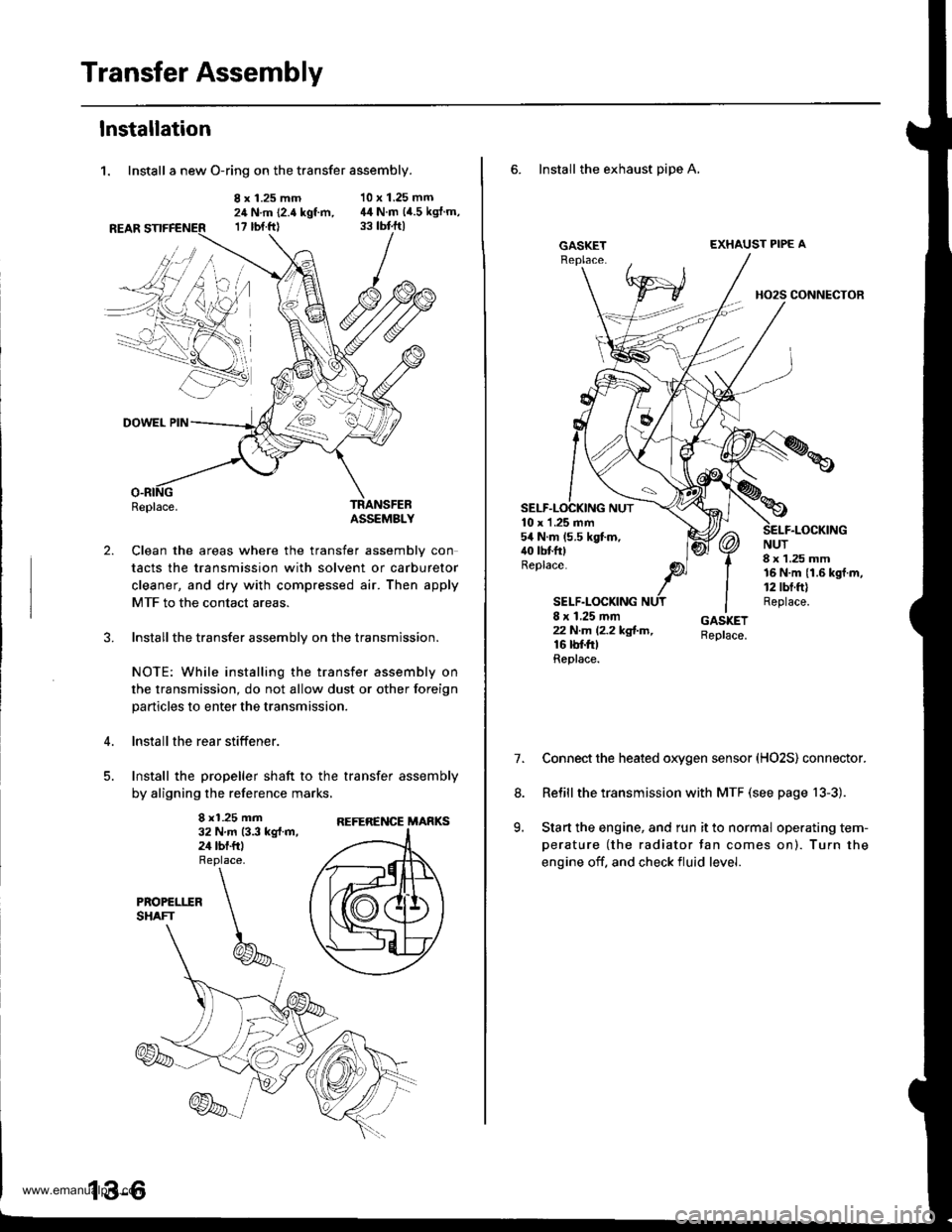
Transfer Assembly
lnstallation
1. Install a new O-ring on the transfer assembly.
8 x 1.25 mm24 N.m (2.4 kgt m,17 rbt.ftl
10 x 1.25 mm44 N.m (4.5 kgJ.m,
2.
DOWEL PIN
Replace.TRANSFEBASSEMBLY
Clean the areas where the transfer assembly con
tacts the transmission with solvent or carburetor
cleaner, and dry with compressed air. Then apply
MTF to the contact areas.
Installthe transfer assembly on the transmission.
NOTE: While installing the transfer assembly on
the transmission, do not allow dust or other foreign
particles to enter the transmission.
lnstall the rear stiffener.
Install the propeller shaft to the transfer assembly
by aligning the reference marks,
8 x1.25 mm32 N.m 13.3 kg{.m,24 tbf.ftl
REFERENCE MARKS
6. Install the exhaust pipe A,
GASKETEXHAUST PIPE A
HO2S CONNECTOR
10 x 1 .25 mm54 N.m (5.5 kgt m,40 tbtfttReplace.
SELF.LOCKING
NUT8 x 1.25 mm16 N.m {1.6 kgf.m,12 tbt.ft)Replace.8 x 1.25 mmzzN.m l2.2kg!-m,16 rbf.trtReplace.
7.Connect the heated oxygen sensor (HO2S) connector.
Relill the transmission with MTF (see page 13-3).
Start the engine, and run it to normal operating tem-
perature (the radiator tan comes on). Turn the
engine off. and check fluid level.
8.
9.
www.emanualpro.com