Radiator HONDA CR-V 2000 RD1-RD3 / 1.G Repair Manual
[x] Cancel search | Manufacturer: HONDA, Model Year: 2000, Model line: CR-V, Model: HONDA CR-V 2000 RD1-RD3 / 1.GPages: 1395, PDF Size: 35.62 MB
Page 1095 of 1395
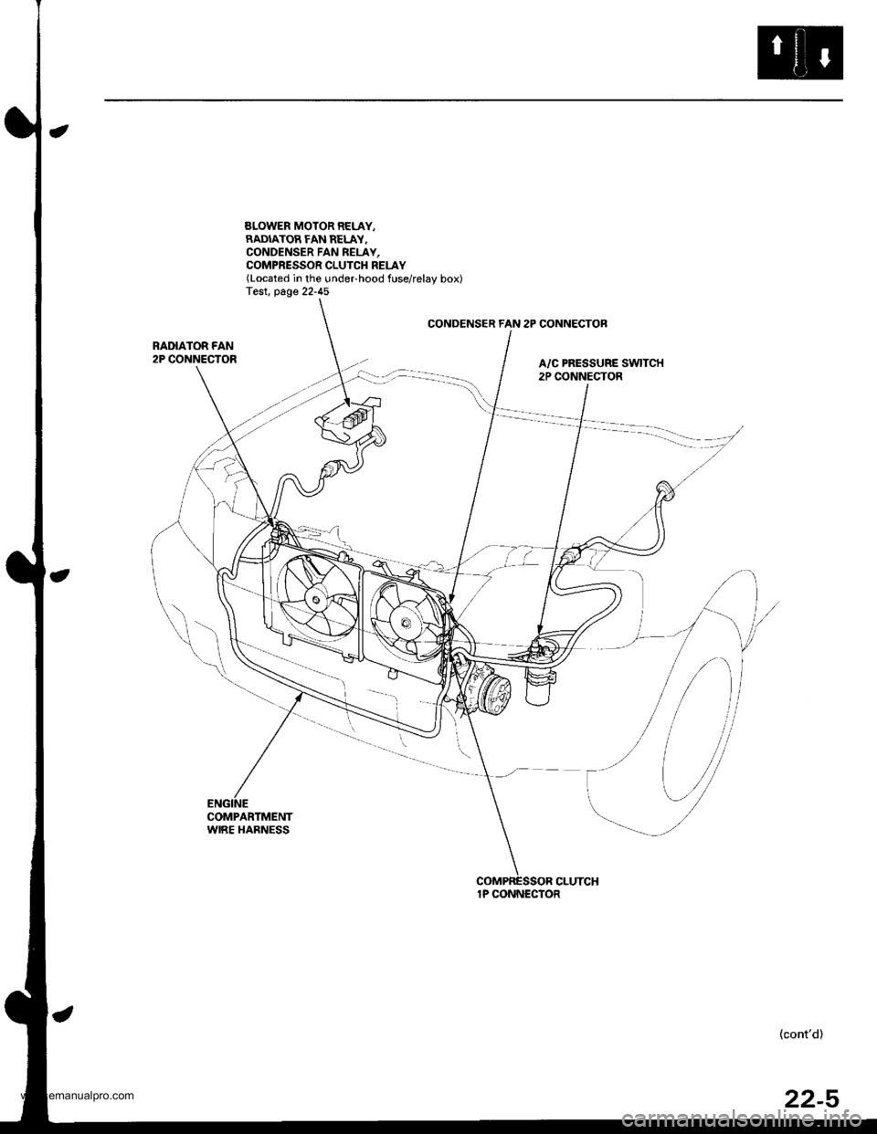
SLOWER MOTOR RELAY,RADIATOR FAN RELAY.CONDENSER FAN REI-AY,COMPRESSOR CLUTCH RELAY(Located in the undeFhood fuse/relay box)Test. page 22-45
CONDENSER FAN 2P CONNECTOB
RADIATOR FAN2P CONNECTORA/C PRESSURE SWITCH2P CONNECTOR
COMPARTMENTWIRE HARNESS
{cont'd)
1P CONNECTOR
22-5
www.emanualpro.com
Page 1100 of 1395
Troubleshooting
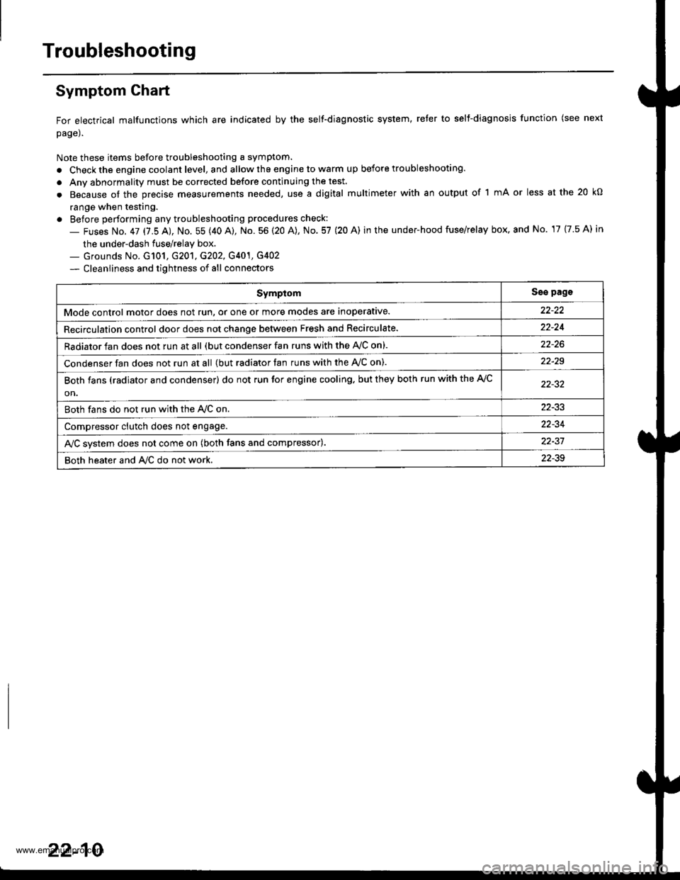
Symptom Ghart
For electrical malfunctions which are indicated by the self-diagnostic system, reter to selt-diagnosjs function (see next
page).
Note these items before troubleshooting a symptom.
. Check the engine coolant level, and allow the engine to warm up before troubleshooting.
. Anv abnormality must be corrected before continuing the test.
. Because of the precise measurements needed, use a digital multimeter with an output of 1 mA or less at the 20 kO
range when testing.
. Before performing any troubleshooting procedures check:
- Fuses No. 47 17.5 AJ, No. 55 (40 A), No. 56 (20 A), No. 57 (20 A) in the under-hood fuse/relay box, and No. 17 {7.5 A) in
the under-dash fuse/relay box.._ Grounds No. G101, G201, G202, G401, G4O2
- Cleanliness and tightness of all connectors
SymptomSse pags
Mode control motor does not run, or one or more modes are inoperative.
Recirculation control door does not change between Fresh and Recirculate.22-24
Radiator fan does not run at all (but condenser fan runs with the AVC on).
Condenser fan does not run at all {but radiator fan runs with the Ay'C on).22-29
Both fans (radiator and condenser) do not run for engine cooling. but they both run with the A,/C
on.
Both fans do not run with the Ay'C on22-33
Compressor clutch does not engage.22-34
AJC svstem does not come on (both fans and compressor).22-37
Both heater and A/C do not work,22-39
22-10
www.emanualpro.com
Page 1116 of 1395
Troubleshooting
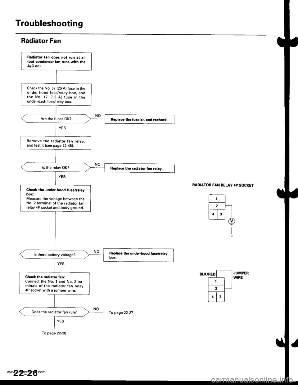
Radiator Fan
MDIATOR FAN RELAY 4P SOCKET
Radiator tan doos not run at sll(but condonser fsn runs with theA/C onl.
Check rhe No. 57 (20 Alfuse in theunderhood fuse/relay box, andthe No. 17 17.5 A) luse in the0nder-dash fuserelay box.
R.pl.c. th. fur€|.l, .nd r.chack.
Remove the radiator fan r6lay,and test it {see page 22-45).
R.pllco tha r.diator frn rehy.
Check the und.r-hood fus./r.l.ybox:Measure the voltage between theNo. 2 terminal ol the .adiator tanrelay 4P socket and body ground.
Chock the radiator tan:Connect the No. 1 and No.2 t€rminals of the radiator fan relay4P socket with a iumper wire.
Does th6 radiator fan run?
fo page 22-28
fo page 22-21
www.emanualpro.com
Page 1117 of 1395
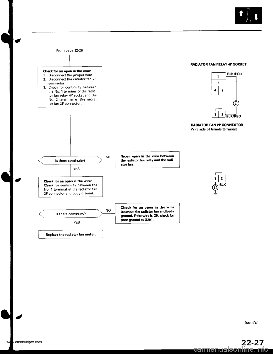
Ch6ck for an open in the wire:1. Disconnect the jumper wire.
2. Disconnect the radiator fan 2P
3. Check for continuity beNveenthe No. l terminal o{the radia-tor fan relay 4P socket and theNo. 2 terminal of the radia'tor fan 2P connector-
Repai. open in the wira betweenthe radiator fan .olay ,nd the radi'atorfan.
Check lor an open in the wi.e:Check for continuity between theNo. 1 terminal oI the radiator fan2P connector and body ground.
Check lor an open in the wir.
b€turosn the radi.tor fan and bodyground. lf ihe wire b OK, check folpoor ground .t G2()l .
ls there continuity?
Replace the radiator tan motor.
Ftom page 22-26
RADIATOR FAN REI-AY 4P SOCKET
BLK/RED
RADIATOR FAN 2P CONNECTORWire side of lemale terminals
(cont'd)
www.emanualpro.com
Page 1118 of 1395
Troubleshooting
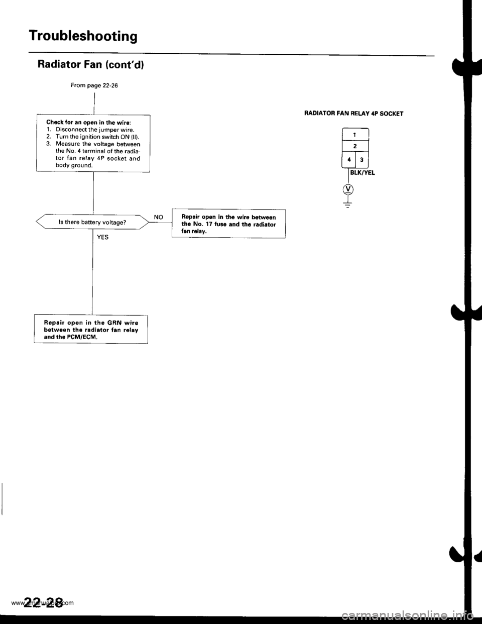
Radiator Fan (cont'dl
From page 22-26
RADIATOR FAN RELAY 4P SOCKET
BLK/YEL
1
2
a
Chock for an open in the wire:'1. Disconnect the jurnper wire.2. Turn the ignition switch ON (ll).3. lleasure the voltage betweenthe No.4terrninal of the radia-tor fan relay 4P socket andbody ground.
R€pair open in th6 wire botwoonthe No. 17 fuso and the radiatolfan .elsy.
ls there battery voltage?
Rep.ir open in the GRN wirebotw€en lhe radiator tan relayand the PCM/ECM.
22-28
www.emanualpro.com
Page 1119 of 1395
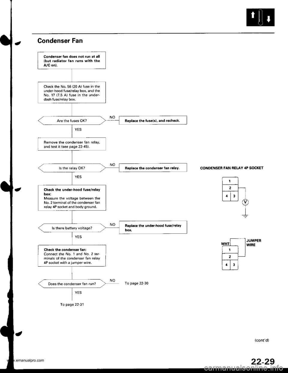
Condenser Fan
CONDENSER FAN RELAY 4P SOCKET
(cont'd)
Condenser lan does not run at alllbut radiator fan runs with theA/C on).
Check the No. 56 (20 A) fuse in theunder hood fuse/relay box, and theNo. 17 {7.5 A) fuse in the under-dash fuse/relay box.
Replace the luse(s), and .echeck.
Remove the condenser fan relay,and test it (see page 22-45).
Replace the condenser fan r€lay.
Check the under-hood luso/relaybox:Measure the voltage between theNo.2 terminal of the condenserfanrelay 4P socket and body ground.
Check the condensff fan:Connect the No. 1 and No. 2 terminals of the condenser lan rclay4P socket with a jumperwire.
Does the condenser fan run?page 22-30
To page 22 31
22-29
www.emanualpro.com
Page 1122 of 1395
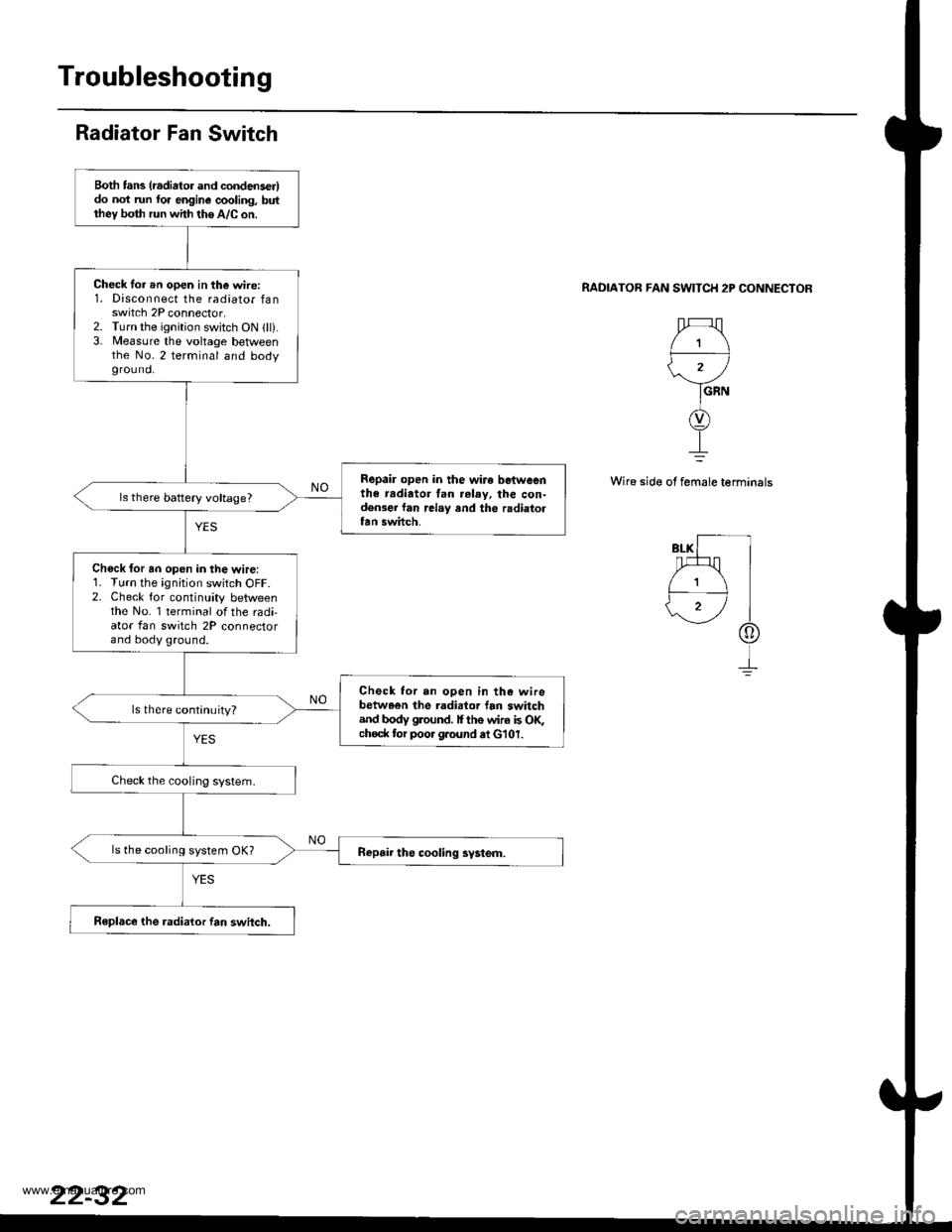
Radiator Fan Switch
RADIATOB FAN SWITCH 2P CONNECTOR
1
'.r
GRN
Wire side of female terminals
Both tans (radiator and condenser)do not run fo. engine cooling, butthey both run with the A/C on.
Check lor rn open in the wire:1. Disconnect the radiator fanswitch 2P connector.2. Turn the ignition switch ON lll).3, Measure the voltage betlveenthe No.2 terminal and bodygrou nd.
Repair open in the wire betweenthe radiator tan relay, the con-densei lan .elay and the radiaiortan swhch.
ls there battery voltage?
Chock for an open in the wire:1. Turn the ignition switch OFF.2. Check for continuity betweenthe No. 1 terminal of the radi-ator fan switch 2P connectorand body ground.
Check for an open in the wirebetween the .adialor fan switchand body glound. I ths wire is OF;choc* tor poor g.ound at G'101.
ls there continuity?
ls the cooling system OK?
Replsce the radialor fan switch.
www.emanualpro.com
Page 1123 of 1395
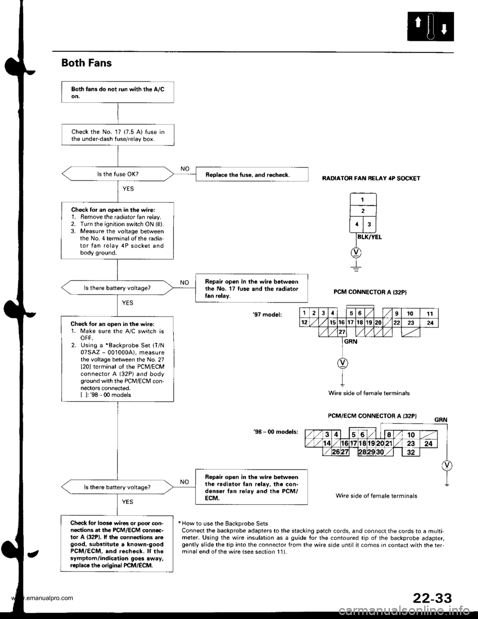
Both Fans
RADIATOR FAN RELAY 'P SOCKET
BLK/YEL
PCM CONNECTOR A I32PI
'9? model:
PCM/ECM CONNECTOR A (32PI
'98 - 0O mod6ls:
Wire side of female terminals
* How to use the Backprobe SetsConnect the backprobe adapters to the stacking patch cords, and connect the cords to a multimeter. Using the wire insulation as a guide for the contoured tip of the backprobe adapter,gently slide the tip into the connector from the wire side until it comes in contact with the terminal end ofthe ware {see section l1).
Check the No. 17 (7.5 A) tuse inthe under-dash fuse/relay box.
Reolace the tuse. and recheck.
Check for an op€n in the wire:1. Remove the radiator fan relay.2. TLrrn the ignition switch ON (ll).
3. Measure the voltage betweenthe No.4 terminalofthe radiator fan relay 4P socket andbody ground.
Repair open in the wire betweenlhe No. 17 luse and the radiatortan relay.
Check for an open in the wire:1. Make sure the A/C switch isOFF.2. Using a *Backprobe Set {T/N07SAZ - 001000A), measurethe voltage between the No. 27I20l terminal ol the PCM/ECMconnector A (32P) and bodyground with the PCM/ECM con-nectors connected.[ ]: '98 - 00 models
Repair open in the wire b€tweenthe.adiator fan ralav, the con-denser tan rolay and the PCM/ECM.
Check tor loose wires or poor con-nodions at the PCM/ECM connoc-tor A (32P1. lf the connections arcgood, substitute a known-goodPCM/ECM, and recheck. It thesymptom/indicalion goes away,r.plrce the original PCM/ECM.
1
2
1
12461011
12t5t61718r9222321
GRN
Wire side oI female terminals
22-33
www.emanualpro.com
Page 1140 of 1395
A/C FilterHeater Unit
Replacement
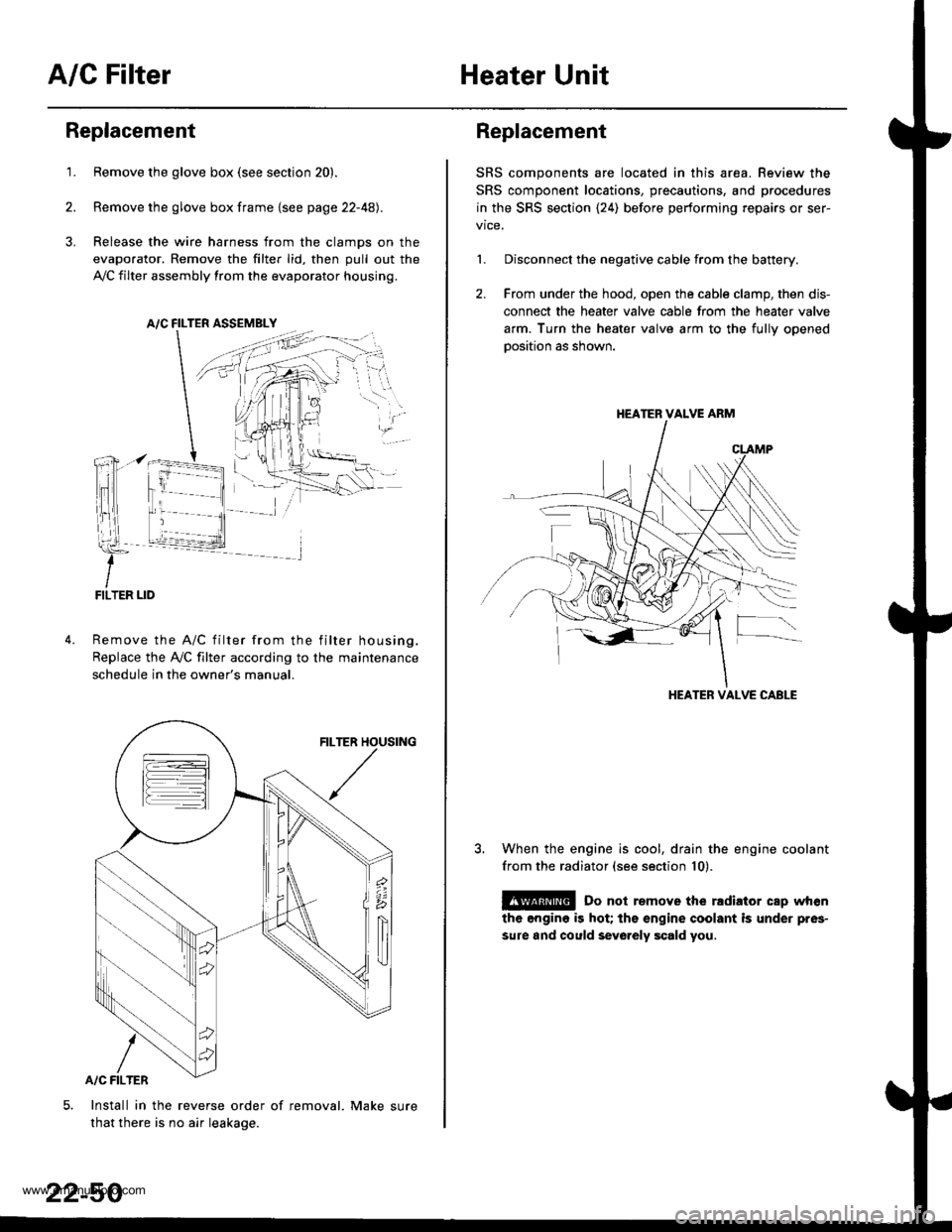
1.Remove the glove box (see section 20).
Remove the glove box frame {see page 22-4A).
Release the wire harness from the clamps on the
evaporator. Remove the filter lid, then pull out the
,VC filter assembly from the evaporator housing.
A/C FILTER ASSEMELY
Remove the A/C filter from the filter housing.
Replace the Ay'C filter according to the maintenance
schedule in the owner's manual.
Install in the reverse order of removal. Make sure
that there is no air leakage.
22-50
Replacement
SRS components are located in this area. Review the
SRS component locations, precautions, and procedures
in the SRS section {24) before performing repairs or ser-
1. Disconnect the negative cable from the battery.
2. From under the hood, open the cable clamp, then dis-
connect the heater valve cable from the heater valve
arm. Turn the heater valve arm to the fullv ooened
oosition as shown.
When the engine is cool, drain the engine coolant
from the radiator (see section 10).
@ Do not remove the rldiator cap when
the engine is hot; the engine coolant is under pres-
sure and could sevo.ely scald you.
HEATER VALVE ARM
HEATER VALVE CABLE
www.emanualpro.com
Page 1148 of 1395
A/C System Service
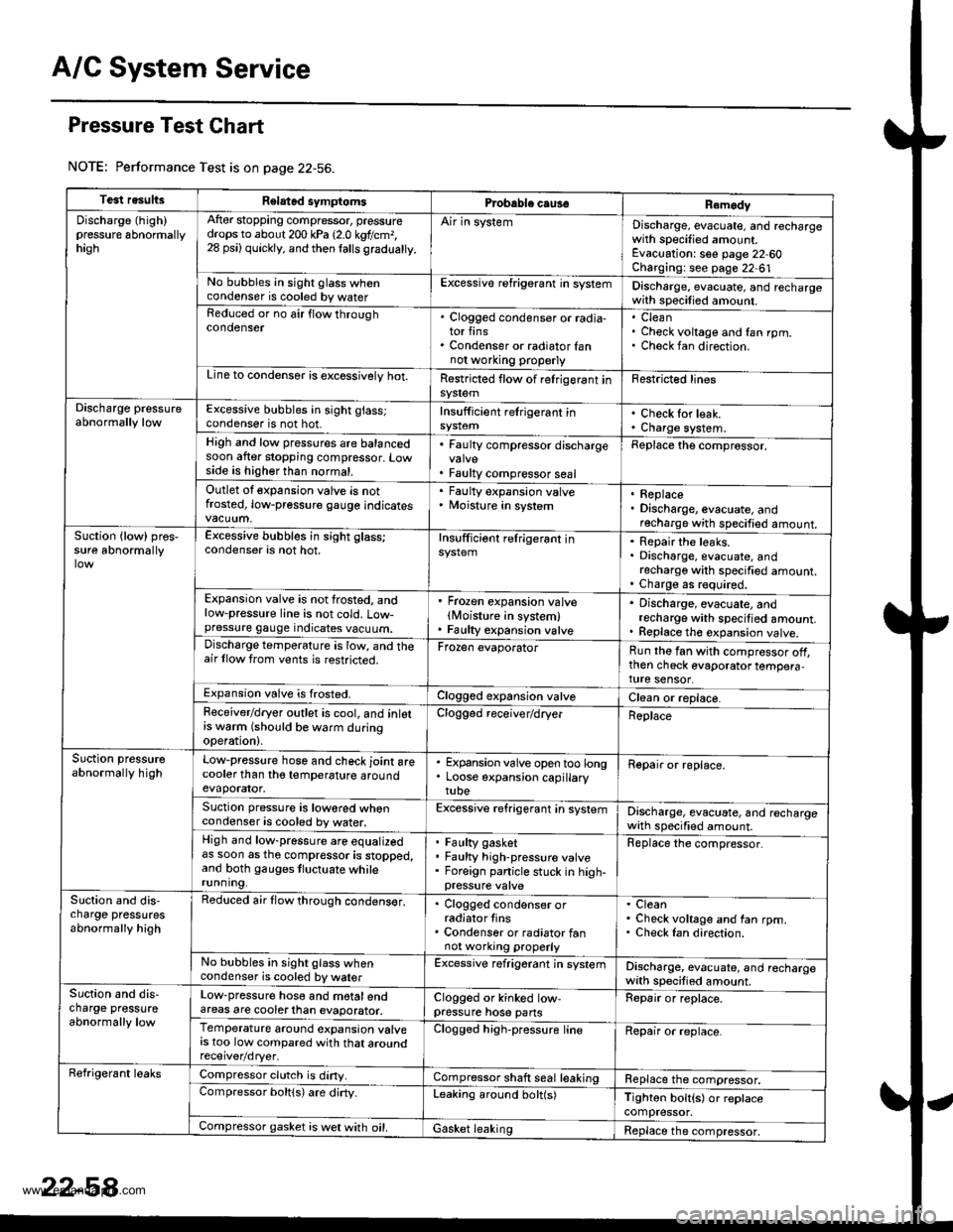
Pressure Test Chart
NOTE: Performance Test is on page 22-56.
Test resultsRelatad symptomsPrcbable caus€Remody
Discharge (high)pressure 6bnormallyhagh
After stopping compressor, pressuredrops to about 200 kPa 12.0 kgtlcm,,28 psi) quickly, and then lalls gradualty.
Air in systemDischarge, evacuate, and rechargewith specified amount.Evacuation: see page 22-60Charging: see page 22-61No bubbles in sight glass whencondenser is cooled by waterExcessive refrigerant in systemDischarge, evacuate, and rechargewith specilied amount.Reduced or no air flow throughcondenser. Clogged condenser or radia-tor fins. Condenser or radiator fannot wo.king properly
CleanCheck voltage and fan rpm.Check fan direction.
Line to condensor is excossivelv hot.Restricted flow of relrigerant insy$emFestricted lines
Discharge pressureabnormally lowExcessive bubbles in sight glass;condenser is not hot.Insufficient retrigerant inCheck for leak.Charge system.High and low pressures are balancedsoon after stopping compressor. Lowside is higher than normal.
. Faulty compressor discharge
. Faulty compressor seal
Replace the comprossor.
Outlet ot expansion valve is notfrosted, low-pressure gauge indicates
' Faulty expansion valve. Moisture in system. Replace. Discharge, evacuate, andrecharge with specified amount.Suction {low) pros,sure abnormallyExcessive bubbles in sight glass;condenser is not hot.Insufficiont relrigerant inRepair the leaks.Discharge, evacuate, andrecharge with specified amount.Charge as r€quired.Expansion valve is not frosted, andlow-pressure line is not cold. Low-pressure gauge indicates vacuum.
' Frozen expansion valvelMoisture in system). Faulty expansion valve
. Discharge, evacuate, andrecharge with specitied amount.. Replace th€ expansion valve.Discharge temperature is low, and theair llow trom vents is restricted.Frozen evaporatorRun the fan with compressor off,then check evaporator tempera,ture sensor.Expansion valve is frosted.Clogged expansion valveClean or replace.Feceiver/dryer outlet is cool, and inlotrs w6rm (should be warm duringoperation).
Clogged receiver/dryerReplace
Suction pressureabnormally highLow-pressure hose and check joint arecooler than tho temperature aroundevaporator.
. Expansion valve open too long. Loose expansion capillarytube
Repair or roplace.
Suction pressure is lowored whencondenser is cooled by water.Excessive refrigerant in systemDischarge, evacuate, and rechargewath specified amount.High and low-pressure are equalizedas soon as tho compressor is stopped,and both gauges tluctuate whilerunning.
Faulty gasketFaulty high-pressure valveForeign panicle stuck in high-
Replace the compressor.
Slction and dis,charge pressutesabnormally high
Reduced air flow through condens€r,. Clogged condenser orradiator tins. Condenser or radiator fannot working properly
CleanCheck voltage and fan rpm.Check Ian direction.
No bubbles in sight glass whencondenser is cooled by walerExcessive refrigerant jn systemDischarge, evacuate, and rechargewith specified amount.Suction and dis-charge pressureabnormally low
Low-pressure hose and motalendareas are cooterlhan evaporator.Clogged or kinked low-pressure hose pansRepair or replace.
Temperature around expansion valvers too low compared with that aroundClogged high-pressure lineRepair or replace.
Refrigerant leaksCompressor clutch is diny.Compressor shaft seal leakingReplace the compressor.Compressor boltls) are dirty.Leaking around bolt(s)Tighton bolt{s) or replacecompressor.Compressor gasket is wet with oil.Gasket leakingReplace the compressor,
www.emanualpro.com