Temperature HONDA CR-V 2000 RD1-RD3 / 1.G Service Manual
[x] Cancel search | Manufacturer: HONDA, Model Year: 2000, Model line: CR-V, Model: HONDA CR-V 2000 RD1-RD3 / 1.GPages: 1395, PDF Size: 35.62 MB
Page 302 of 1395
PGM-FI System
Engine Coolant Temperature (ECTI Sensor {cont'd)
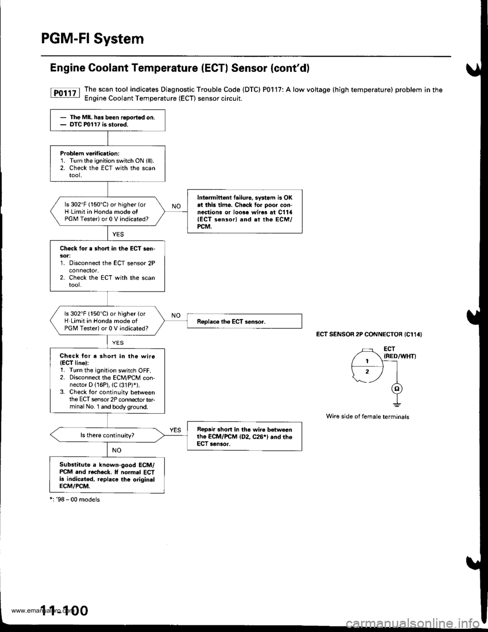
[F011' The.scan tool indicates Diagnostic Trouble Code (DTC) P0117: A low voltage (high temperature) problem in the: Engine Coolant Temperature (ECT) sensor circuit.
ECT SENSOR 2P CONNECTOR {C114I
Wire side of female terminals
- The MIL has been rooortod on.- DTC ml17 is sto.od.
Problem verification:1. Turn the ignition switch ON {ll).2. Check the ECT with the scantool,
Intermittont f.ilure, sysiom is OKat thk time. Check for poor con-nections or loo3e wire3 at C1lil(ECT sensorl and et the ECM/PCM.
ls 302"F (150'C) or higher (or
H Limit in Honda mode otPGM Tester) or 0 V indicated?
Check for a Bhort in the ECT sen-301:'1. Disconnect the ECT sensor 2Pconnefior,2. Check the ECT with the scantool.
ls 302"F (150"C)or higher (or
H-Limit in Honda mode ofPGM Tester) or 0 V indicated?
Check for r shorl in the wirs(EgT linel:1. Turn the ignition switch OFF.2. Disconnect the ECM/PCM con-nector D (16P), (C (31P)*1.3. Check tor continuity betweenthe ECT sensor 2P connectorterminal No. 1 and bodyground.
Repair short in the wir€ betweenthe ECM/FCM (D2, C26rl ,nd th6ECT senaor.
ls there continuity?
Substitute a known-good ECM/PCM and recheck. It normal ECTi! indicatod, replaco the oiiginalECM/PCM.
*:'98 - 00 models
1-1
www.emanualpro.com
Page 303 of 1395
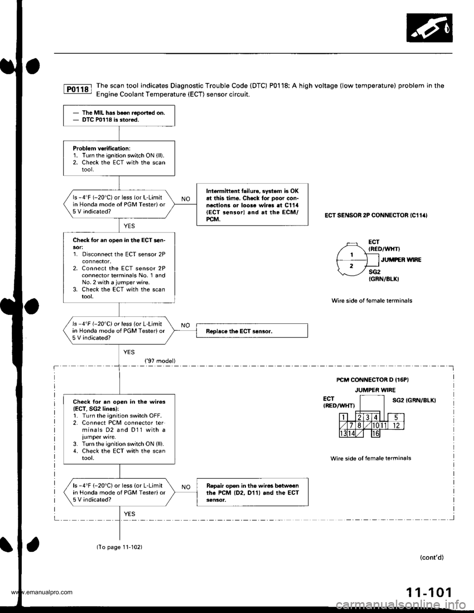
The scan tool indicates Diagnostic Trouble Code {DTC) P0118: A high voltage {low temperature) problem in the
Engine Coolant Temperature (ECT) sensor circuit.
ECT SENSOR 2P CONNECTOB (C11ill
ECT(ncD/wlrT)
ECTIREDAAIHT)
Wirc side of lemale terminals
sG2(GRN/8LKI
PCM CONNECTOR D {T6PI
JUMPER WIRE
JUi,IPEB WNE
IGRN/BLX}
Wire side oI female terminals
(cont'd)
1 1-101
The MIL has be€n reported on.DTC P01'18 is stor€d.
Problem verification:1. Turn the ignition switch ON {ll).2. Check the EcT with the scantool-
Intermiftent tailu.€,3ystem is OKat this time, Checl foJ poor con-n€ction3 or loose wires et C1'14(ECT ren3or) and at the ECM/PCM.
ls -4"F (-20'C) or less (or L-Limitin Honda mode ot PGM Tester) or5 V indicated?
Check for an open in the ECT sen-
1. Disconnect the ECT sensor 2Pconnector.2. Connect the ECT sensor 2Pconnector terminals No. 1 andNo. 2 with a jumper wire.3. Check the ECT with the scantool.
ls -4'F (-20'C) or less (or L'Limitin Honda mode of PGM Tester)or5 V indicated?
Check for an open in the wiies{ECT, SG2 lines):1. Turn the ignition switch OFF.2. Connect PCM connector terminals D2 and D11 with a
iumper wire.3. Turn the ignition switch ON {ll}.4. Check the ECT with the scantool,
ls -4"F (-20'C) or less (or L-Limitin Honda mode of PGM Testerior5 V indicated?
Repair open in th6 wire! botwe€nthe PCM lD2, D'l1l and the ECT3€n30t.
('97 model)
(To page 11-102)
www.emanualpro.com
Page 304 of 1395
PGM-FI System
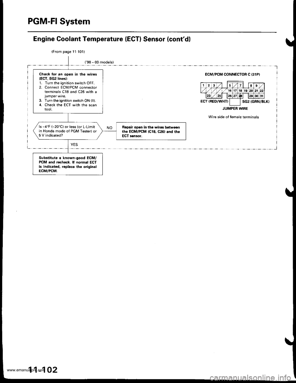
Chack lor an open in the wires(ECT, SG2 lines):1. Turn the ignition switch OFF.2. Connect ECM/PCM connectorterminals C18 and C26 with a
3. Turn the ignition switch ON (ll).
4. Check the ECT with the scantool.
ls -4"F (-20"C) or less (or L-Limitin Honda mode of PGM Testerlor5 V indicated?
Ralpair open in tho wir6s b6twe€ntho ECM/PCM 1C18, c26l 6nd thoECT sensor.
Substitute a known-good ECM/PCM and rech.ck. lf normal ECTis indicrted, replace ths originslECM/PCM.
Engine Goolant Temperature (ECTI Sensor (cont'dl
(From page 11 101)
ECM/PCM OONNECTOR C 13lPI
(GRN/BLK)
JUMPER WIRE
Wire side of temale terminals
17I9
,/ 1617't8'1920n
ECT IRED/WHTIsG2
11-102
www.emanualpro.com
Page 351 of 1395
ldle Control System
System Description
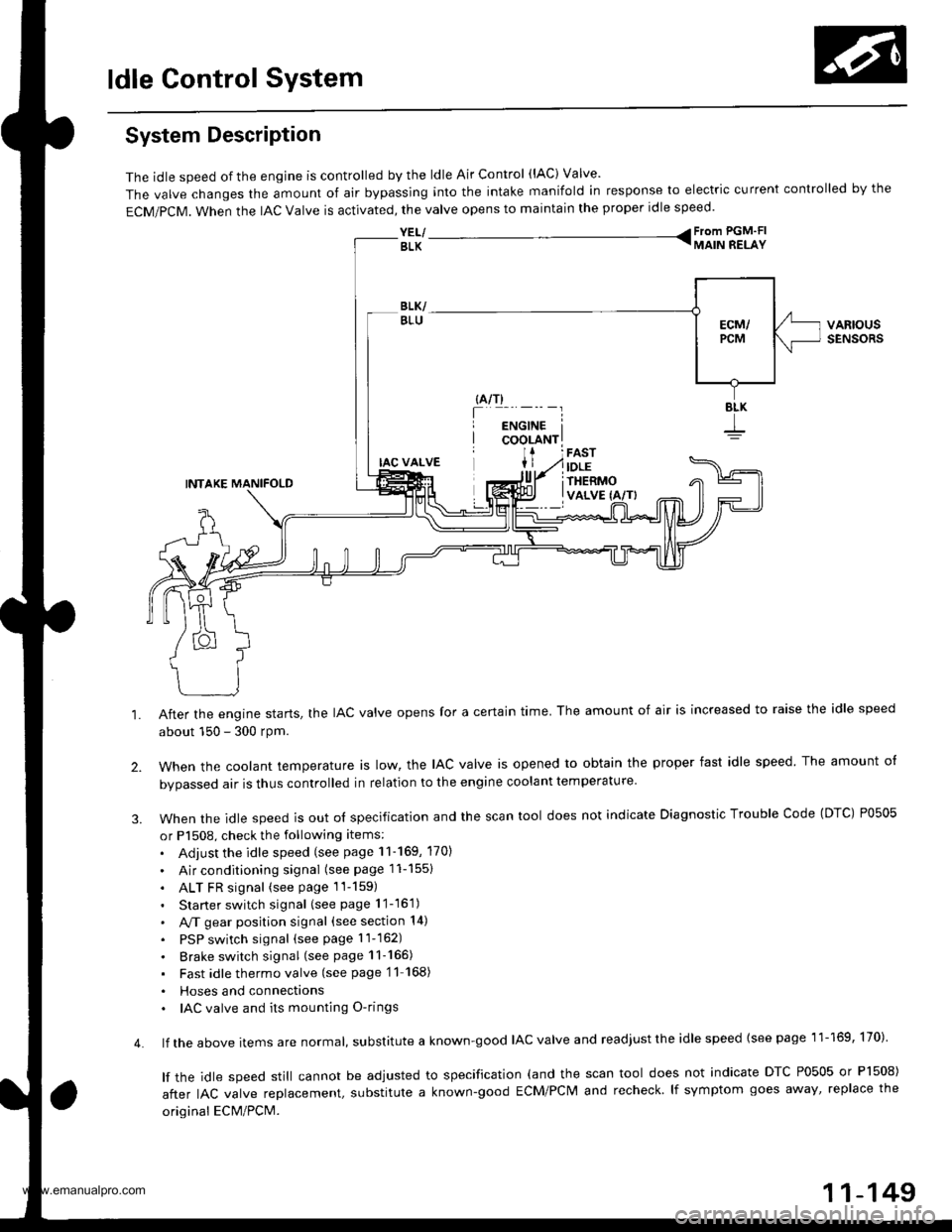
The idle speed of the engjne is controlled by the ldle Air Control (lAC) Valve'
The valve changes the amount of air bypassing into the intake manifold in response to electric current controlled by the
ECM/PCM. When the lAc valve is activated, the valve opens to maintain the proper idle speed.
YEL/ From PGM'FI
BLK TMAIN RELAY
VARIOUSSENSORS
4.
IAC VALVE
INTAKE MANIFOLD
After the engine starts, the IAC valve opens for a certain time. The amount of air is increased to raise the idle speed
about 150 - 300 rpm.
when the cootant temperature ts row, the lAc valve is opened to obtain the proper fast idle speed The amount o{
bvoassed air is thus controlled in relation to the engine coolant temperature
When the idle speed is out o{ specification and the scan tool does not indicate Diagnostic Trouble Code (DTC) P0505
or P1508, check the following items:
. Adjust the idle speed (see page 11-169, 170)
. Air conditioning signal (seepagell-1551
. ALT FR signal (see page 1l-159)
. Starter switch signal (see page 11-16'1)
. A,/T gear position signal (see section 14)
. PSP switch signal (seepagell-162)
. Brake switch signal (see page 11-165)
. Fast idlethermovalve (see page'11 168)
. Hoses and connecttons. IAC valve and its mounting O-rings
lf the above items are normat, suDslitute a known-good IAC valve and readjust the idle speed {see page 11-169, 170)
lf the idle speed still cannot be adjusted to specification (and the scan tool does not indicate DTC P0505 or Pl508)
after IAC valve reolacement, substitute a known-good ECM/PCM and recheck lf symptom goes away' replace the
original ECM/PCM.
11-149
www.emanualpro.com
Page 352 of 1395

ldle Control System
ldle Control System
I P0505 | The scan tool indicates Diagnostic T.ouble Code (DTCI PO5O5: ldlecontrol svstem mattunction.
NOTE: lf DTC P1508 is stored at the same time as DTC P0505, troubleshoot DTC P1508 first. then troubleshoot DTC p0505.
Possibls Cause
. IAC valve mechanical malfunction. Throttle body clogged port, improper adlustment. Intake manifold gasket leakaging. Intake air hose loose leakaging. Vacuum hose leakaging
a ECT sensor incorrect output. Throttle Position sensor incorrect output
Troubleshooting Flowchart
The MIL has been reDorted on.DTC P0505 is sto.ed.
Problem verificationi1. Start the engine. Hold theengine at 3,000 rpm with noload (in Park or neutral) untilthe radiator Ian comes on, thenlet it idle.2. With the scan tool, check thelollowing items.- Throttle position should beapprox. 10% with the throt-tle {ully closed.- Engine coolant temperature shorJld be 194 - 205'F(90 - 96"C).lf they are not within thespec., repair the faulty sen-sor circuit.3 Check the engine speed atidle with no-load conditions:headlights, blower fan. reardefogger, radiator lan, and airconditioner are not operaling,
Inte.mittent failure. syltem is OKat this time.ls it 750 {730)* i 50 rpm?
ls il 700 (680)' rpm or less?
{To page 11-151)(To page 1'l-151)
l:'99 - 00 models
www.emanualpro.com
Page 370 of 1395
ldle Control System
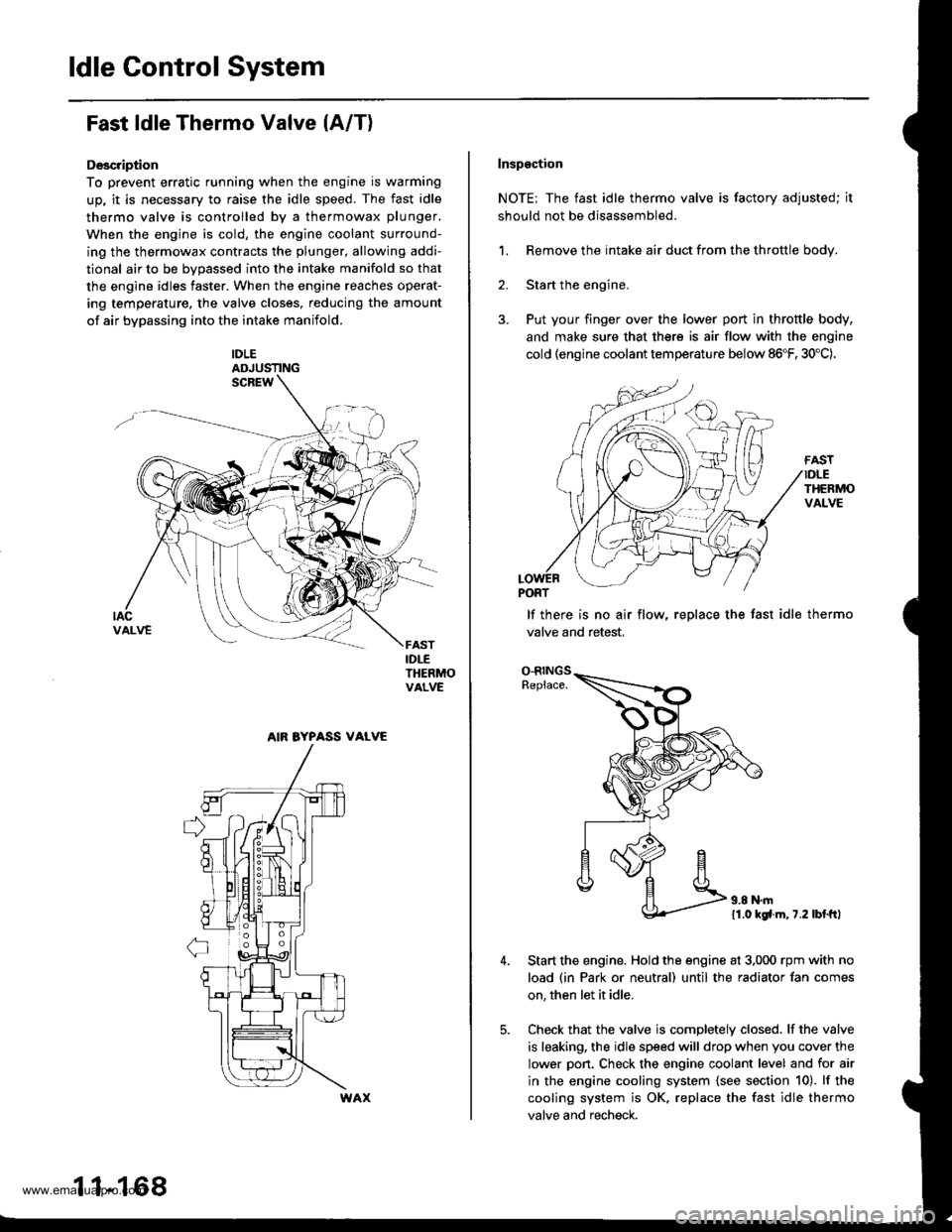
Fast ldle Thermo Valve lA/T)
Description
To prevent erratic running when the engine is warming
up, it is necessary to raise the idle speed. The fast idle
thermo valve is controlled by a thermowax plunger.
When the engine is cold, the engine coolant surround-
ing the thermowax contracts the plunger, allowing addi-
tional air to be bvDassed into the intake manifold so that
the engine idles faster. When the engine reaches operat-
ing temperature. the valve closes, reducing the amount
of air bypassing into the intake manifold.
IDLEADJUSTING
IDLETHERMOVALVE
AIR BYPASS VALVE
11-168
Inspgction
NOTE: The fast idle thermo valve is factory adjusted; it
should not be disassembled.
1. Remove the intake air duct from the throttle body.
2. Start the engine,
3. Put your finger over the lower port in throttle body,
and make sure that there is air flow with the engine
cold (engine coolant temperature below 86"F, 30'C).
lf there is no air flow, replace the fast idle thermo
valve and retest,
O-RINGSReplace.
11.0 kgfl.m, 7.2 lbl.ftl
Start the engine. Hold the engine at 3,000 rpm with no
load (in Park or neutral) until the radiator fan comes
on, then let it idle.
Check that the valve is completely closed. lf the valve
is leaking, the idle speed will drop when you cover the
lower pon. Check the engine coolant level and for air
in the engine cooling system {see section 10). lf the
cooling system is OK, replace the fast idle thermo
valve and recheck.
www.emanualpro.com
Page 405 of 1395
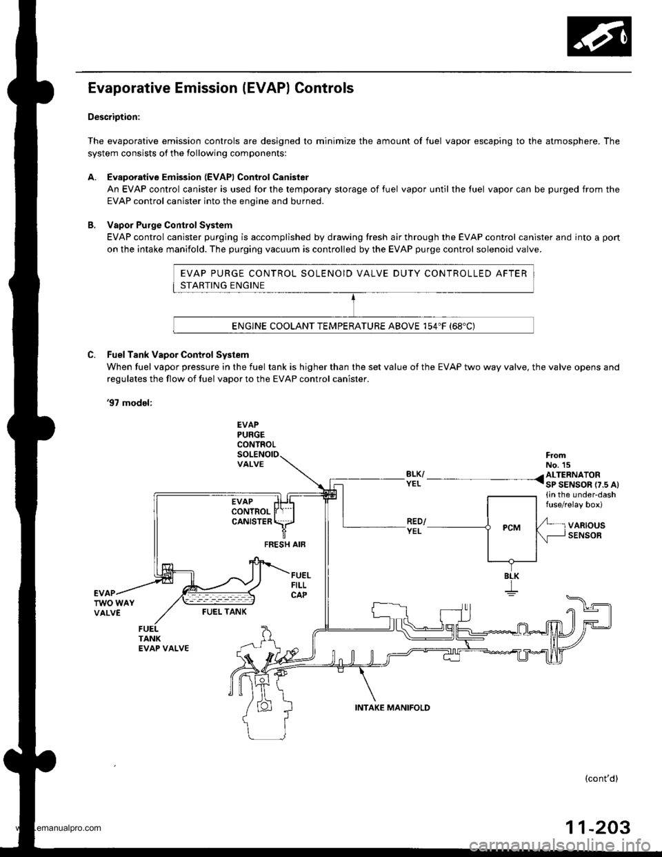
EVAP PURGE CONTROL SOLENOID VALVE DUTY CONTROLLED AFTER
STARTING ENGINE
ENGINE COOLANT TEMPERATURE ABOVE 154"F (68'C)
Evaporative Emission (EVAP) Controls
Description:
The evaporative emission controls are designed to minimize the amount of fuel vapor escaping to the atmosphere. The
system consists of the following components:
A. Evaporative Emission (EVAPI Control Canister
An EVAP control canister is used for the temporary storage of fuel vapor until the luel vapor can be purged from the
EVAP control canister into the enqine and burned.
B. Vapor Purge ConirolSystem
EVAP control canister purging is accomplished by drawing fresh air through the EVAP control canister and into a pon
on the intake manifold. The purging vacuum is controlled by the EVAP purge control solenoid valve.
C. Fuel Tank Vapor Control System
When fuel vapor pressure in the fuel tank is higher than the set value of the EVAP two way valve, the valve opens and
regulates the flow ot fuel vapor to the EVAP control canister.
'97 model:
EVAPPURGECONTROL
VALVEFromNo. 15BLK/ /ALTERNATORYEL I sP SENSOR r7.s At(in the under-dashfuse/relay box)
VARIOUSSENSORFEESH AIF
BLK
I
FUEI- TANK
(cont'd)
11-203
INTAKE MANIFOLD
www.emanualpro.com
Page 425 of 1395
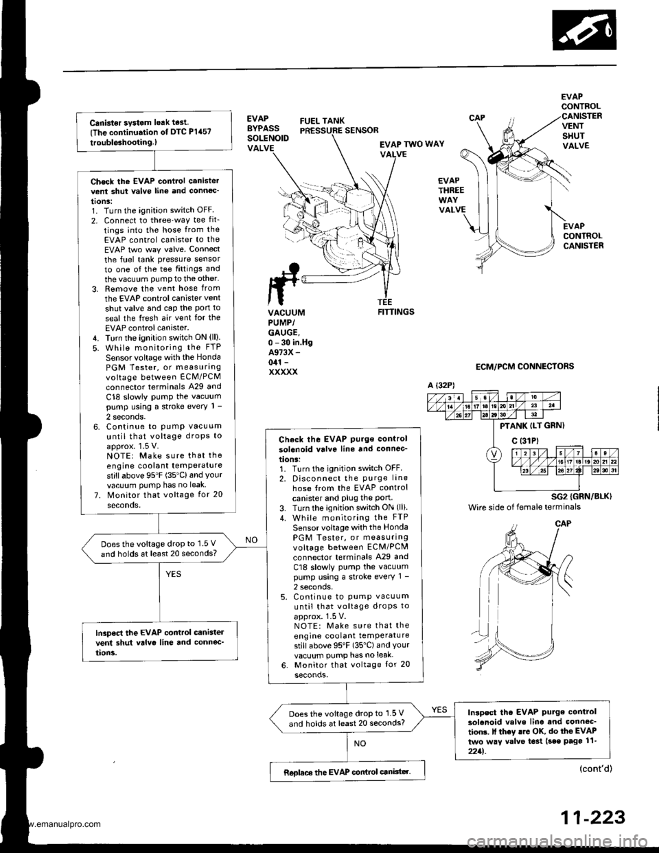
Canbter system leak test
{The continuation of DTC P1457
trouble3hootin9.)
Chock the EVAP control canistervent shut valve line and connoc'
tonS:1. Turn the ignition switch OFF
2. Connect to three'way tee fit_
tings into the hose from the
EVAP control canister to the
EVAP two way valve. Connect
the fuel tank pressure sensor
to one of the tee fittings and
the vacuum PumP to the other'
3. Remove the vent hose from
the EVAP control canister vent
shut valve and cap the Pon to
seal the fresh air vent Ior the
EVAP control canister.4. Turn the ignition switch ON (ll).
5. While monitoring the FTP
Sensor voltage with the Honda
PGM Tester, or measurangvoltage between ECM/PCM
connector terminals A29 and
C18 slowly PumP the vacuumpump using a stroke every 1 -
2 seconds.6. Continue to PumP vacuum
until that voltage droPs to
approx. 1.5 V.NOTE: Make sure that the
engine coolant temPeraturestillabove 95'F (35'Cland Yourvacuum PumP has no leak
7. Monitor that voltage for 20
seconds.
Check the EVAP Pu.ge control
solenoid valve line and connec-
tions:1. Turn the ignition switch OFF.
2. Disconnect the Purge lane
hose from the EVAP control
canister and Plug the Port3. Turn the ignition switch ON (lli.
4. While monitoring the FTP
Sensor voltage with the Honda
PGM Tester, or measuringvoltage between ECM/PCM
connector terminals A29 and
Cl8 slowly PumP the vacuumpump using a stroke every 1 -
2 seconds.5. Continue to pump vacuum
until that voltage droPs to
approx. 1-5 V.NOTE: Make sure that the
engine coolant temPeraturestill above 95'F (35"C) and Yourvacuum pump has no leak-
6. Monitor that voltage tor 20
seconds.
Doesthe voltage drop to 1.5 V
and holds at least 20 seconds?
lGp€ct the EVAP control cani3tel
vent 3hut valvo line and connec_
tion5.
Inlpect tho EVAP Putge control
solenoid valvo line and connec'
tion3. It th6y lro OK, do the EVAP
two way valve te3t (seo page 11-
2211.
Does the voltage drop to 1.5 V
and holds at least 20 seconds?
Reolace the EVAP conirol canister.
EVAPBYPASSSOLENOIDVALVE
FUEL TANK
EVAPCONTROL
VENTSHUTVALVE
EVAPCONTROLCANISTER
SENSOR
EVAP TWO WAYVALVE
EVAPTHREE
VALVE
ttrrL
ta
VACUUMPUMP/GAUGE,0 - 30 in.HgA973X -
041 -
XXXXX
FITTINGS
ECM/PCM CONNECTORS
A {32P)
PTANK ILT GRN)
c (31Pt
SG2 {GRN/BLK)
Wire side of female terminals
{cont'd)
11-223
www.emanualpro.com
Page 480 of 1395
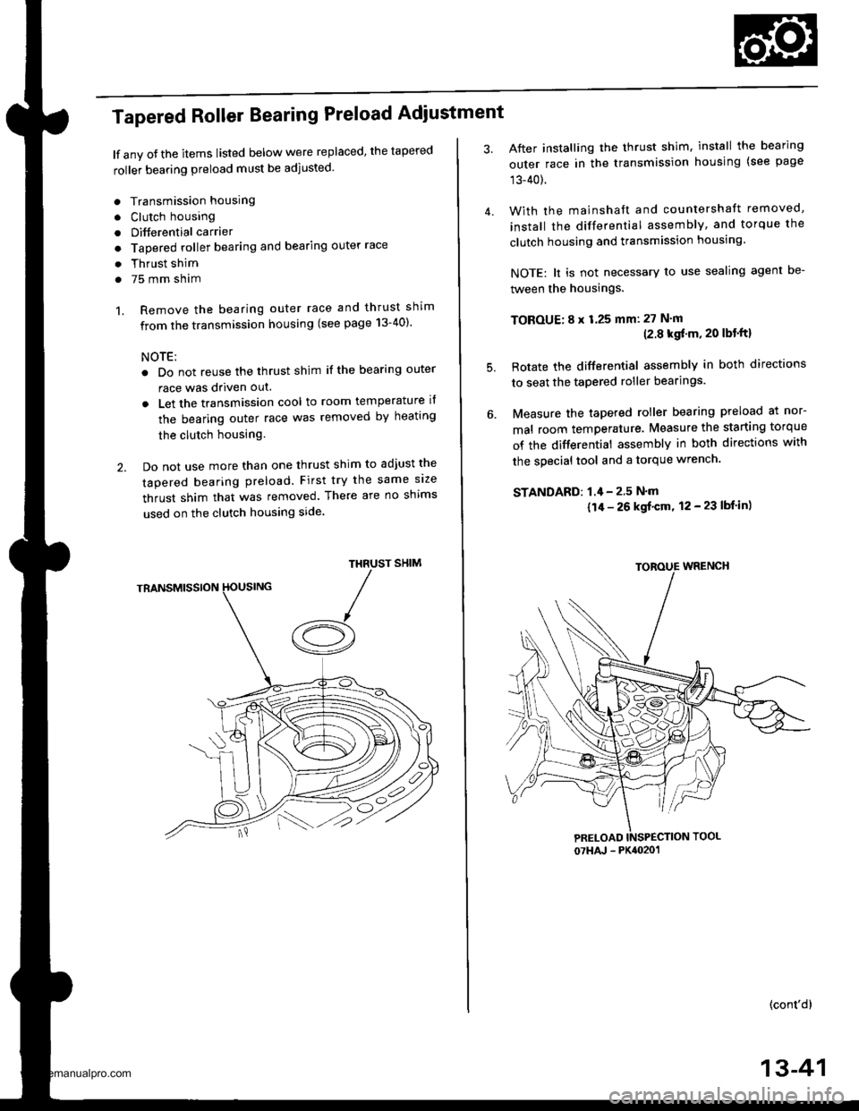
Tapered Roller Bearing Preload Adiustment
lf any oJ the items listed below were replaced, the tapered
roller bearing preload must be adjusted.
. Transmission housing
. Clutch housing
. Differential carrier
o Tapered roller bearing and bearing outer race
. Thrust shim
. 75 mm sham
1. Remove the bearing outer race and thrust shim
from the transmission housing (see page 13-40)'
NOTE:
. Do not reuse the thrust shim if the bearing outer
race was driven out.
. Let the transmission cool to room temperature il
the bearing outer race was removed by heating
the clutch housing.
2. Do not use more than one thrust shim to adjust the
tapered bearing preload. First try the same size
thrust shim that was removed. There are no shims
used on the clutch housing side
SHIMTHRUST
/A
After installing the thrust shim, install the bearing
outer race in the transmission housing (see page
13-40).
With the mainshaft and countershaft removed,
install the differential assembly, and torque the
clutch housing and transmission housing.
NOTE: lt is not necessary to use sealing agent be-
tween the housings.
TOBOUE; 8 x 1.25 mm: 27 N'm(2.8 kgf'm, 20 lbt'ftl
Rotate the differential assembly in both directions
to seat the tapered roller bearings.
Measure the tapered roller bearing preload at nor-
mal room temperature. Measure the starting torque
of the differential assembly in both directions with
the special tool and a torque wrench.
STANDAFD: 1.4 - 2.5 N'm
{1/r - 26 kgf'cm, 12 - 23 lbf in)
(cont'd)
4.
5.
07HAJ - PK4020'�1
13-41
www.emanualpro.com
Page 499 of 1395
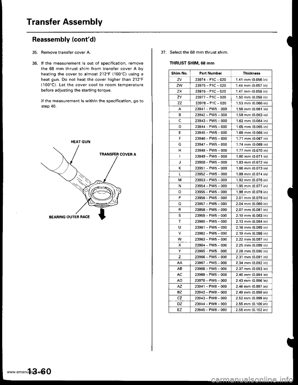
Transfer Assembly
Reassembly (cont'd)
Remove transfer cover A.
lf the measurement is out of specification, remove
the 68 mm thrust shim from transfer cover A by
heating the cover to almost 212'F (100'C) using a
heat gun. Do not heat the cover higher than 212F
(100"C). Let the cover cool to room temperature
before adjusting the starting torque.
lI the measurement is within the specification, go to
step 40.
COVER A
BEARING OUTER RACE
35.
36.
HEAT GUN
13-60
37. Select the 68 mm thrust shim.
THRUST SHIM, 68 mm
Shim No.Part NumberThickne3s
zv23914-P1C-0201.41 mm (0.056 in)
zw23975-P1C-020'1.44 mm 10.057 in)
zx23916 PlC -020'1.47 mm (0.058 in)
ZI23917 -P1C-O201.50 mm (0.059 in)
zz23978-PlC-0201.53 mm (0.060 in)
23941 - PW5 0001.56 mm {0.061 in)
23942-PWs-0001.59 mm (0.063 in)
c23943-PW5-000't.62 mm (0.064 in)
D23944 PW5 - 0001.65 mm (0.065 in)
E23945-PWs-0001.68 mm (0.066 in)
F23946-PW5-0001.71 mm 10.067 in)
G23947-PW5-000'1.74 mm 10.069 in)
23948-PWs-0001.77 mm (0.070 in)
23949-PWs-0001.80 mm (0.071 in)
239s0-PW5-0001.83 mm (0.072 in)
K23951 - PW5 - 0001.86 mm (0.073 in)
L23952-PWs-0001.89 mm {0.074 in)
239s3-PWs-0001.92 mm {0.076 ini
N23954-PW5-0001.95 mm (0.077 in)
o23955-PW5-0001.98 mm (0.078 in)
P23956 - PW5 , 0002.01 mm (0.079 in)
o23957-PWs-0002.04 mm (0.080 in)
R23958-PWs-0002.07 mm (0.081 in)
23959-PW5-0002.10 mm (0.083 in)
T23960-PW5-0002.13 mm (0.084 in)
U23961 - PW5 - 0002.16 mm (0.085 in)
23962-PW5-0002.19 mm (0.086n)
23963-PWs-0002.22 mm (0.087n)
X23964-PWs-0002.25 mm (0.089n)
23965,PWs-0002.28 mm 10.090n)
23966-PW5-0002.31 mm {0.091 in)
23967-PWs-0002.34 mm (0.092 in)
AB23968-PWs-0002.37 mm (0.093 in)
AC23969-PWs-0002.40 mm {0.094 in}
AD23970-PW5-0002.43 mm (0.096 in)
M23941 - PW8 - 0002.46 mm {0.097 'n}
BZ23942-PW8-0002.49 mm (0.098 in)
cz23943-PW8-0002.52 mm {0.099 ini
DZ23944-PW8-0002.55 mm (0.100 in)
EZ23945-PW8-0002.58 mm (0.102 ini
www.emanualpro.com