torque HONDA CR-V 2000 RD1-RD3 / 1.G Service Manual
[x] Cancel search | Manufacturer: HONDA, Model Year: 2000, Model line: CR-V, Model: HONDA CR-V 2000 RD1-RD3 / 1.GPages: 1395, PDF Size: 35.62 MB
Page 525 of 1395
2.
L
E Position
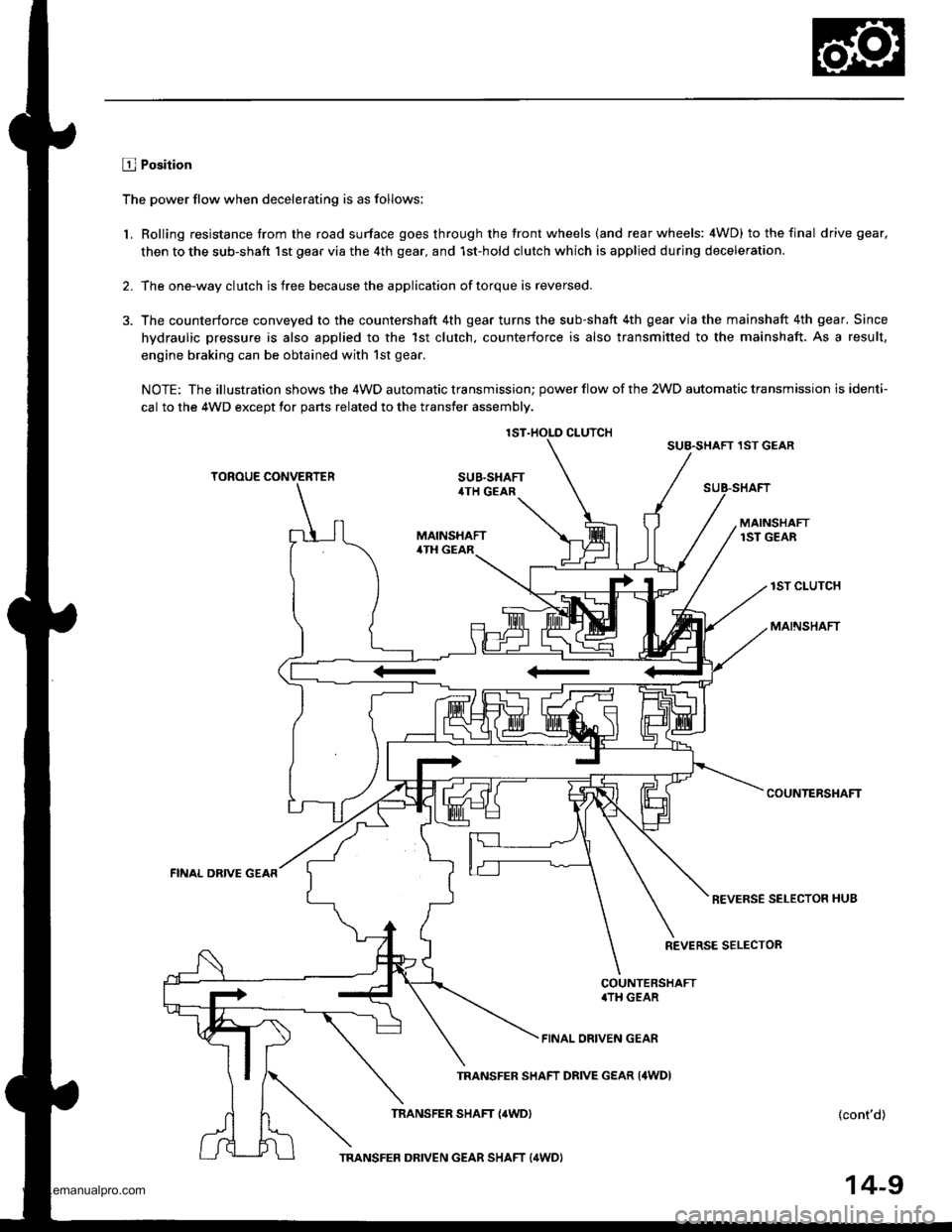
The power flow when decelerating is as follows:
Rolling resistance trom the road surface goes through the tront wheels (and rear wheels: 4WD) to the final drive gear.
then to the sub-shaft lst gear via the 4th gear. and 1st-hold clutch which is applied during deceleration.
The one-way clutch is free because the application of torque is reversed.
The counterforce conveyed to the countershaft 4th gear turns the sub-shaft 4th gear via the mainshaft 4th gear. Since
hydraulic pressure is also applied to the 1st clutch. counterforce is also transmitted to the mainshaft. As a result,
engine braking can be obtained with'lst gear.
NOTE: The illustration shows the 4WD automatic transmission; power flow of the 2WD automatic transmission is identi-
cal to the 4WD except tor parts related to the transfer assembly.
J.
SUB.SHAFT 1ST GEAR
TOROUE CONVERTER
FINAL DRIVE GEAR
SUB.SHAFT{TH GEAR
MAINSHAFTlST GEAR
lST CLUTCH
MAINSHAFT
COUNTERSHAFT
REVERSE SELECTOR HUB
REVERSE SELECTOR
COUNTERSHAFTIITH GEAR
FINAL ORIVEN GEAR
TRANSFER SHAFT DRIVE GEAR {4WDI
TRANSFEB SHAFT {{WD){cont'd}
lST.HOLD CLUTCH
TRANSFER DRIVEN GEAR SHAFT {,lWDl
14-9
www.emanualpro.com
Page 540 of 1395
Description
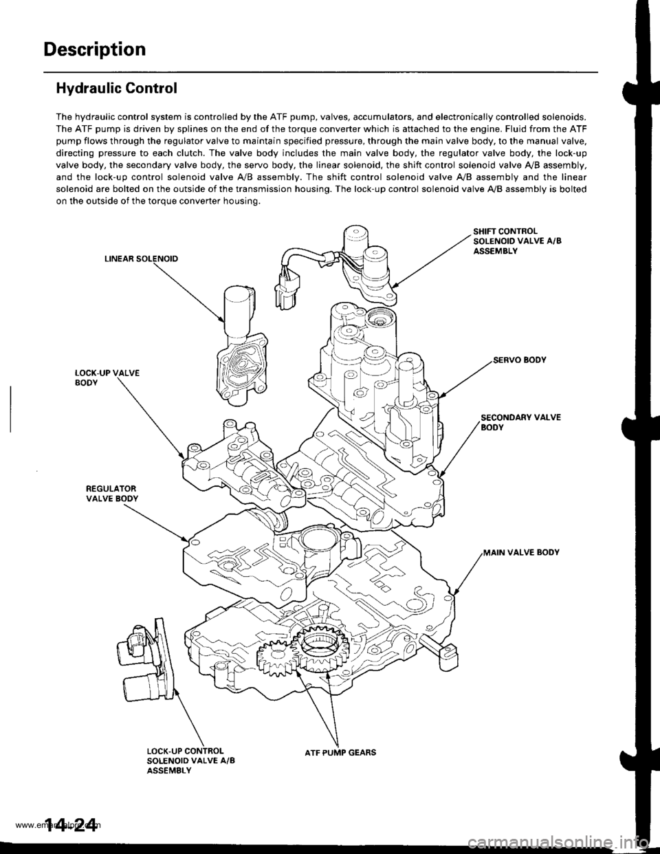
Hydraulic Control
The hydraulic control system is controlled by the ATF pump, valves, accumulators, and electronically controlled solenoids.
The ATF pump is driven by splines on the end of the torque converter which is aftached to the engine. Fluid from the ATF
pump flows through the regulator valve to maintain specified pressure, through the main valve body, to the manual valve,
directing pressure to each clutch. The valve body includes the main valve body, the regulator valve body, the lock-up
valve body, the secondary valve body, the servo body, the linear solenoid, the shift control solenoid valve Ay'B assembly,
and the lock-up control solenoid valve A/B assembly. The shift control solenoid valve A,/B assembly and the linear
solenoid are bolted on the outside of the transmission housing. The lock-up control solenoid valve A,/B assembly is bolted
on the outside of the torque converter housing.
LINEAR
SHIFT CONTROLSOLENOID VALVE A/BASSEMBLY
SECONDARY VALVEBODY
REGULATORVALVE BOOY
VALVE BODY
SOLENOID VALVE A/BASSEMELY
N
ATF PUMP GEARS
14-24
www.emanualpro.com
Page 542 of 1395
Description
Hydraulic Control (cont'd)
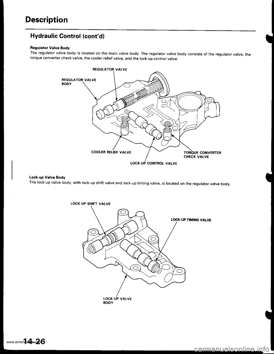
Regulator Valve Body
The regulator valve body is located on the main valve body. The regulator valve body consists of the regulator vatve, thetorque converter check valve. the cooler relief valve, and the lock-up control valve.
Lock-up Valve Body
The lock-up valve body, with lock-up shift valve and lock-up timing valve, is located on the regulator valve body.
LOCK.UP SHIFT
NMING VALVE
COOLER RELIEF VALVE
VALVE
14-26
www.emanualpro.com
Page 543 of 1395
Regulator Valve
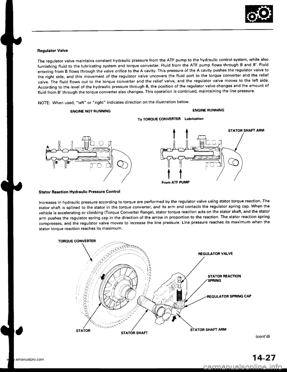
The regulator valve maintains constant hydraulic pressure from the ATF pump to the hydraullc control system, while also
furnishing fluid to the lubricating system and torque converter. Fluid from the ATF pump flows through B and B'. Fluid
entering from B flows through the valve orifice to the A cavity. This pressure of the A cavity pushes the regulator valve to
the right side. and this movement of the regulator valve uncovers the fluid port to the torque converter and the relief
valve. The fluid flows out to the torque converter and the relief valve, and the regulator valve moves to the left side.
According to the level of the hydraulic pressure through B, the position of the regulator valve changes and the amount of
fluid from B,through the torque converter also changes. This operation is continued, maintaining the line pressure.
NOTE; When used, "|eft" or "right" indicates direction on the illustration below.
ENGINE NOT RUNNING
STATOR SHAFT ABM
Stator Reaction Hydraulic Pressurs Control
Increases in hydraulic pressure according to torque are performed by the regulator valve using stator torque reaction. The
stator shaft is splined to the stator in the torque converter, and its arm end contacts the regulator spring cap When the
vehicle is accelerating or climbing (Torque Converter Range), stator torque reaction acts on the stator shaft, and the stator
arm pushes the regulator spring cap in the direction of the arrow in proportion to the reaction. The stator reaction spring
compresses, and the regulator valve moves to increase the line pressure. Line pressure reaches its maximum when the
stator torque reaction reaches its maximum.
TOROUE CONVERTER
REGULATON VALVE
STATOR REACTION
TOR SPRING CAP
(cont'd)
ENGINE RUNNING
To TOROUE CONVERTER Lubtication
STATONSTASHAFTATOF SHAFT ARM
14-27
www.emanualpro.com
Page 545 of 1395
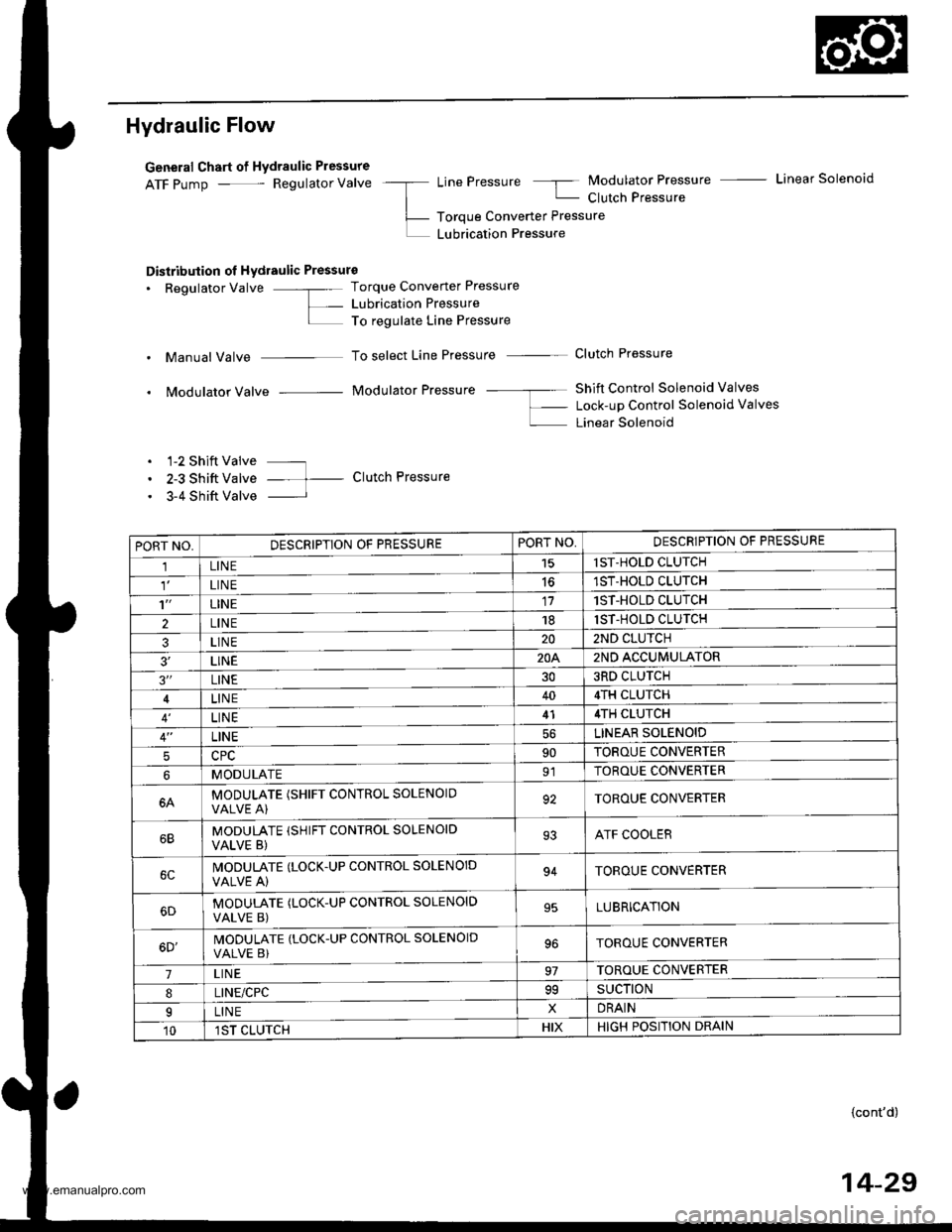
Hydraulic Flow
General Chart of Hydraulic Pressure
ATF pump - Regulator Valve -a LinePressure 5 Modulator Pressure - Linear Solenoid
| - Clutch Pressure
L- Toroue Converter Pressure
L LUbrication Pressure
Distribution ol Hydraulic Pressure
. Regulator Valve -"- Torque Converter Pressure
L- Lubrication PressureI To regulate Line Pressure
. Manual Valve To select Line Pressure - Clutch Pressure
. Modulator Valve Modulator Pressure -- ---- Shift Control Solenoid Valves
f- Lock-up Control Solenoid valves
L Linear Solenoid
. 1-2 Shift Valve ---
. 2-3 Shift Valve -- t- Clutch Pressure
. 3-4 Shift Valve I
PORT NO,DESCRIPTION OF PRESSUREPORT NO,DESCRIPTION OF PRESSURE
1LINE15lST-HOLD CLUTCH
LIN E1ST-HOLD CLUTCH
't'LINE171ST-HOLD CLUTCH
2LINE181ST-HOLD CLUTCH
3LINE202ND CLUTCH
3'�LINE20A2ND ACCUMULATOR
3"LINE303RD CLUTCH
LINE404TH CLUTCH
LINE414TH CLUTCH
LINELINEAR SOLENOID
590TOROUE CONVERTER
MODULATE91TOROUE CONVERTER
6AMODULATE (SHIFT CONTROL SOLENOIOVALVE A)92TOROUE CONVERTER
MODULATE (SHIFT CONTROL SOLENOID
VALVE B)93ATF COOLER
IVODULATE (LOCK.UP CONTROL SOLENOID
VALVE A)94TOROUE CONVERTER
MODUTATE (LOCK-UP CONTROL SOLENOID
VALVE B)95LUBRICATION
6D'MODULATE (LOCK-UP CONTROL SOLENOID
VALVE B)TOROUE CONVERTER
7LIN E97TOROUE CONVERTER
8LINE/CPC99SUCTION
ILINExDRAIN
101ST CLUTCHHIXHIGH POSITION DRAIN
{cont'd)
14-29
www.emanualpro.com
Page 546 of 1395
Description
Hydraulic Flow (cont'dl
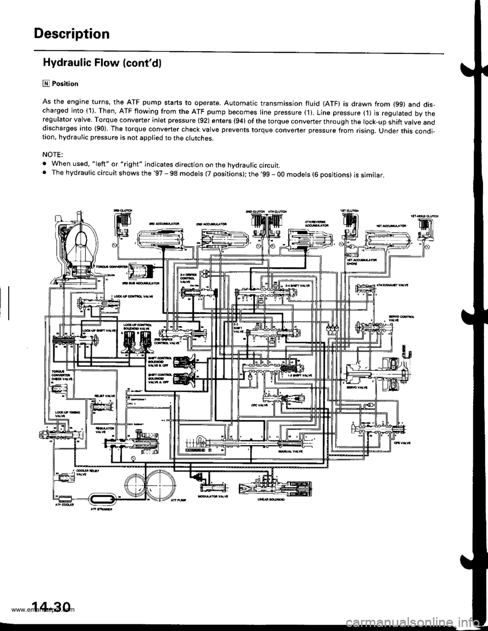
lll Position
As the engine turns, the ATF pump starts to operate. Automatic transmission fluid (ATF) is drawn from (99) and dis-charged into (1). Then, ATF flowing from the ATF pump becomes line pressure ('l). Line pressure (1) js regulated by theregulator valve. Torque converter inlet pressure {92) enters (94) of the torque conveTter through the lock-up shift valve anddischarges into (90) The torque converter check valve prevents torque converter pressure from rising. Under this condi-tion, hydraulic pressure is not applied to the clutches.
NOTE;
. When used. "|eft" o. "right" indicates direction on the hvdraulic circutt.. The hydraulic circuit shows the '97 - 98 models {7 positions}; the '99 - 00 models (6 positions) is similar.
'lF'.j.l
14-30
www.emanualpro.com
Page 549 of 1395
![HONDA CR-V 2000 RD1-RD3 / 1.G Service Manual
E] or E Position (97 - 98 Models), and D Position (99 - 00 Modelsl
1. lst Gear
Fluid flow through the torque converter circuit is the same as in E] position. Line pressure flows to the manual valve HONDA CR-V 2000 RD1-RD3 / 1.G Service Manual
E] or E Position (97 - 98 Models), and D Position (99 - 00 Modelsl
1. lst Gear
Fluid flow through the torque converter circuit is the same as in E] position. Line pressure flows to the manual valve](/img/13/5778/w960_5778-548.png)
E] or E Position ('97 - 98 Models), and D Position ('99 - 00 Modelsl
1. lst Gear
Fluid flow through the torque converter circuit is the same as in E] position. Line pressure flows to the manual valve
and the modulator valve. Line pressure changes to modulator pressure (6) at the modulator valve and to line pressure
{4) at the manual valve. Modulator pressure (6) flows to the left end of the 1-2 shift valve and the 3-4 shift valve
because shift control solenoid valve A is turned oFF and B is turned oN by the PcM. The 1-2 shift valve is moved to
the right side. Line pressure {4) changes to 'lst clutch pressure (10} at the 1-2 shift valve and the orifice The 1st clutch
pressure (10) is applied to the 1st clutch and the 1st accumulator; the vehicle will move as the engine power is trans-
mitted.
NOTE:
. When used, "left" or "right" indicates direction on the hydraulic circuit.
. The hvd rau lic circuit shows th e '97 - 98 models (7 positions); the '99 - 00 models {6 positions) issimilar.
(cont'dl
14-33
www.emanualpro.com
Page 553 of 1395
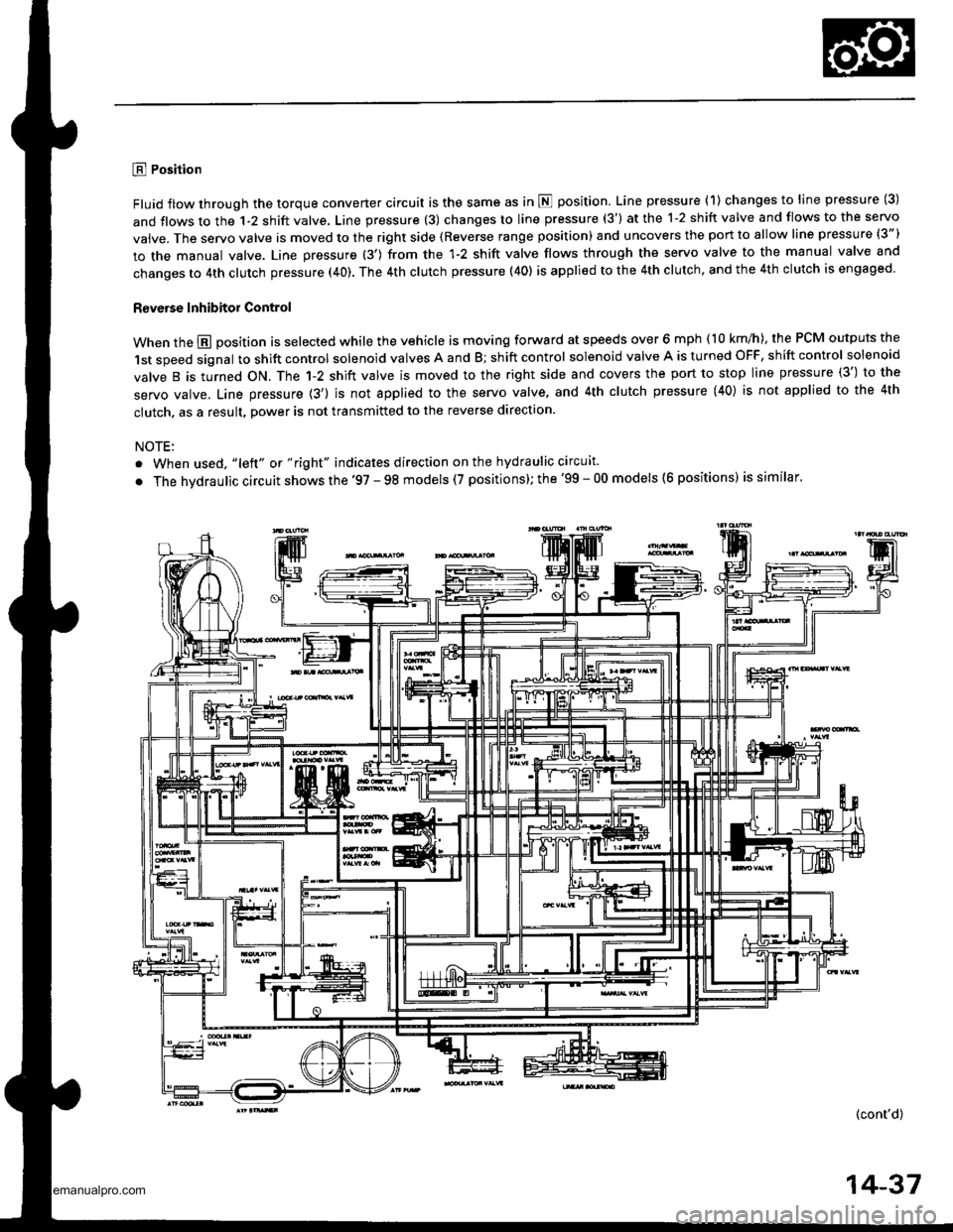
E Position
Fluid flow through the torque converter circuit is the same as in N position. Line pressure (1) changes to line pressure (3)
and flows to the 1-2 shift valve. Line pressure (3) changes to line pressure (3') at the 1-2 shift valve and flows to the servo
vaive. The servo valve is moved to the right side (Reverse range position) and uncovers the port to allow line pressure (3")
to the manual valve. Line pressure (3') from the 1-2 shift valve flows through the servo valve to the manual valve and
changes to 4th clutch pressure (40). The 4th clutch pressure (40) is applied to the 4th clutch, and the 4th clutch is engaged.
R€verse Inhibitor Control
When the @ position is selected while the vehicle is moving forward at speeds over 6 mph (10 km/h), the PCM outputs the
1st speed signal to shift control solenoid valves A and B; shift control solenoid valve A is turned OFF, shift control solenoid
valve B is turned ON. The 1-2 shift valve is moved to the right side and covers the port to stop line pressure (3') to the
servo valve. Line pressure {3') is not applied to the servo valve, and 4th clutch pressure (40} is not applied to the 4th
clutch, as a result, power is not transmitted to the reverse direction.
NOTE:
. When used, "lelt" ot " right" indicates direction on the hydraulic circuit.
. The hvdraulic circuit shows the '97 - 98 models (7 positions); the '99 - 00 models (6 positions) is similar'
(cont'd)
14-37
www.emanualpro.com
Page 554 of 1395
Description
Hydraulic Flow (cont'dl
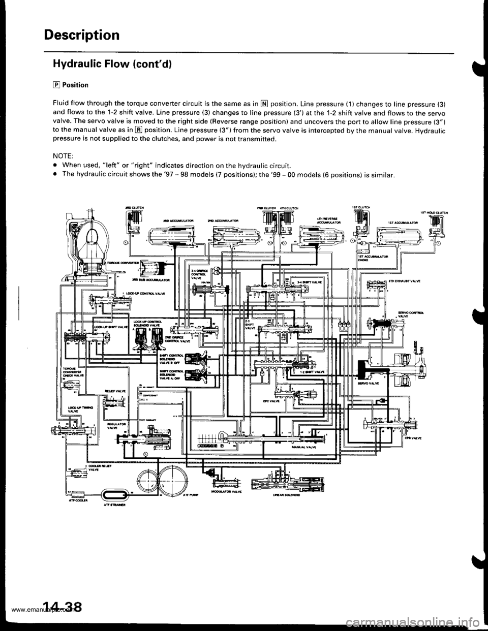
E Position
Fluid flow through the torque converter circuit is the same as in fl position. Line pressure ( 1) changes to line pressure (3)
and flows to the 1-2 shift valve. Line pressure (3) changes to line pressure {3') at the 1-2 shift valve and flows to the servovalve. The servo valve is moved to the right side (Reverse range position) and uncovers the port to allow line pressure (3")
to the manual valve as in E position. Line pressure (3") from the servo valve is intercepted by the manual valve. Hydraulicpressure is not supplied to the clutches, and power is not transmitted.
NOTE:
. When used, "left" or "right" indicates direction on the hydraulic circuit.. The hydraulic circuit shows the '97 - 98 models (7 positions); the '99 - 00 models (6 positions) issimilar.
14-38
www.emanualpro.com
Page 555 of 1395
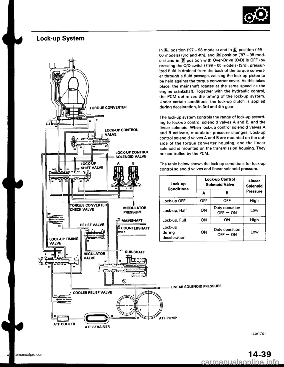
Lock-up System
TOROUE CONVERTER
In E position ('97 - 98 models) and in E position ('99 -
OO models) (3rd and 4th), and E position ('97 - 98 mod-
els) and in E position with Over-Drive (O/D) is OFF (by
pressing the O/D switch) ('99 - 00 models) (3rd), pressur-
ized fluid is drained from the back of the torque convert-
er through a fluid passage, causing the lock-up piston to
be held against the torque converter cover, As this takes
Dlace, the mainshaft rotates at the same speed as th8
engine crankshaft. Together with the hydraulic control,
the PCM optimizes the timing of the lock-up system.
Under certain condltions. the lock-up clutch is appli€d
during deceleration, in 3rd and 4th gear.
The lock-up system controls the range of lock-up sccord-
ing to lock-up control solenoid valves A and B, and ths
linear solenoid. When lock-up control solenoid valves A
and B activate. modulator pressure changes. Lock-up
control solenoid valves A and B are mounted on the out-
side of the torque converter housing, and the linear
solenoid is mounted on the transmission housing. They
are controlled bv the PCM.
The table below shows the lock-up conditions for lock-up
control solenoid valves and linear solenoid pressure.
LINEAR SOLENOID PRESSURE
(cont'd)
LOCK.UP CONTROL' VALVE
LOCK.UP CONTROLSOLENOID VALVE
AB
MODULATORPf,ESSURE
MAINSHAFT
COUNTERSHAFT
SUB.SHAFT
Lock-up
Conditions
Lock-up Conirol
Solenoid valveLinaal
Solenoid
PrgssulsAB
Lock-up OFFOFFOFFHigh
Lock-up, HalfONDuty operation
OFF - ONLow
Lock-up, FullONONHigh
Lock-up
during
deceleration
ONDuty operation
OFF - ON
RELIEF VALVE
LOCK'UP TIMINGVALVE
COOLER RELIEF VALVE
ATF COOLERATF STRAINER
ATF PUMP
14-39
www.emanualpro.com